ABSTRACT
WANG, ANJING. The SILO Architecture: Exploring Future Internet Design. (Under the direction of Dr. Rudra Dutta and Dr. George Rouskas.)
The architecture of the modern Internet encompasses a large number of principles, concepts and assumptions that have evolved over several decades. In this dissertation, we argue that while the current architecture houses an effective design, it is not itself effective in enabling evolution.
In order to achieve architectural flexibility to enable evolution and to explore future Internet design, we introduce the SILO architecture, a meta-design framework within which the system design can change and evolve. We present some insights about architectural research that guided our work, as well as the goals we formulated for our architecture. We then describe that architecture itself, connecting it with relevant prior and current research work.
One of the great benefits of SILO is cross-service tuning optimization. We detail our ap-proach to enable cross-service tuning, and then we present sample tuning algorithms, and experiential results.
In order to sustain the Internet evolving and to enable others to contribute, we introduce the architectural support for programming (services, tuning algorithms, and applications) within the SILO architecture. We also discuss an early case study on the usefulness of SILO in lowering the barriers to contribution and innovation in network protocols.
We validate the promise of enabling change by demonstrating how our recent study supports virtualization, as well as integration with other architectures.
Network virtualization has become a new trend in recent years and has been considered an important aspect of network architecture design. However, current understanding of network virtualization is still limited. We investigate the entire spectrum of network virtualization and propose a fundamental way to define network virtualization by using network resources. We also investigate its fundamental resources. In this context, we present a SILO architectural extension for network virtualization.
In an effort to promote SILO in deployment, we investigate the integration of the SILO architecture with several other architectures in GENI. IMF functions as SILO’s measurement plan, while ORCA works as the resource control plan. We discuss our work and experimental results, and the flexibility of the SILO architecture in working with other architectures.
c
Copyright 2010 by Anjing Wang
The SILO Architecture: Exploring Future Internet Design
by Anjing Wang
A dissertation submitted to the Graduate Faculty of North Carolina State University
in partial fulfillment of the requirements for the Degree of
Doctor of Philosophy
Computer Science
Raleigh, North Carolina 2010
APPROVED BY:
Dr. George Rouskas Co-chair of Advisory Committee
Dr. Ilia Baldine
Dr. Vincent Freeh Dr. Edward Gehringer
DEDICATION
To my mom and dad, who put all their trust in me and supported my studies abroad;
To my wife, who gave up a good job and being close to her parents and friends in order to support me with all her heart;
To my little sister and her family, who have taken care of our parents while I am on my journey here; and
BIOGRAPHY
Anjing Wang is a PhD candidate in the Department of Computer Science at North Carolina State University. He received his bachelor’s and master’s degrees from Department of Informa-tion and CommunicaInforma-tion, Xian Jiaotong University, China in 2000 and 2003, respectively. After working with Lenovo (Beijing), Nortel Networks (Beijing) and Nortel Networks (California), he joined NC State University under the instruction of Dr. Rudra Dutta (advisor) and Dr. George Rouskas (co-advisor). He is the author of several patents (registered in China) in the wireless LAN area. His current research focus upon networking architecture design.
Anjing served as an at-large officer of the Computer Science Graduate Student Association (CSC GSA) for two years, and he was also a representative of CSC GSA in the University GSA, which is a bridge between NCSU graduate students and CSC students. He was nominated as an Outstanding Teaching Assistant of the Graduate School and named Outstanding Teaching Assistant in the Computer Science Department of NCSU on Apr 24, 2009.
ACKNOWLEDGEMENTS
This work was funded by NSF Grants CNS-0626103, NeTS-FIND: The SILO Architecture for Services Integration, controL, and Optimization for the Future Internet, and by NSF GENI Project 1718, GENI IMF: Integrated Measurement Framework and Tools for Cross-Layer Ex-perimentation.
TABLE OF CONTENTS
List of Tables . . . ix
List of Figures . . . x
Chapter 1 Introduction . . . 1
1.1 Current Internet Design . . . 1
1.2 In Search of Future Internet Architecture . . . 2
1.3 Related Work on Composable Architecture . . . 4
1.3.1 Function-based Communication Subsystem . . . 4
1.3.2 X-kernel . . . 4
1.3.3 Coyote: Fine-Grain Configurable Services . . . 5
1.3.4 Role-Based Architecture . . . 6
1.3.5 A Recursive Network Architecture . . . 6
1.3.6 Tng: Transport Next-Generation . . . 6
1.4 Our Exploration . . . 6
Chapter 2 The SILO Architecture . . . 8
2.1 Design Philosophy and Principles . . . 8
2.1.1 SILO Philosophy: Designing for Change . . . 9
2.1.2 Three Principles . . . 10
2.1.3 Support for Evolution and Innovation . . . 12
2.2 Basic Architecture . . . 13
2.2.1 Services . . . 14
2.2.2 Methods . . . 15
2.2.3 Silo . . . 15
2.2.4 Knobs . . . 16
2.2.5 SILO Control . . . 16
2.3 Comparisons with Similar Architectures . . . 17
Chapter 3 The SILO Software Prototype . . . 19
3.1 Prototype Component Description . . . 20
3.1.1 The SILO-Enabled Application . . . 20
3.1.2 The SILO API . . . 20
3.1.3 The SILO Management Agent . . . 21
3.1.4 The SILO Tuning Agent . . . 21
3.1.5 The SILO Construction Agent . . . 22
3.1.6 The SILO Ontology . . . 22
3.1.7 SILO Services . . . 23
3.1.8 SILO Tuning Algorithms and Tuning Strategies Storage . . . 23
3.1.9 Universe of Services Storage . . . 24
3.2 Mapping the Prototype Framework to the SILO Architecture . . . 24
3.3.1 SILO Endpoint . . . 26
3.4 Several Implementation Choices . . . 26
3.5 Software Releases . . . 27
Chapter 4 Architectural Enabling of Cross-Service Tuning. . . 29
4.1 Motivation: From Cross-Layer to Cross-Service . . . 29
4.2 Realization . . . 30
4.2.1 Design of Knobs . . . 30
4.2.2 Design of SILO Tuning Agent . . . 31
4.2.3 Design of Tuning Algorithms . . . 32
4.2.4 Design of Measurement Services . . . 33
4.2.5 Recapping the SILO Cross-Service Tuning . . . 33
4.2.6 Envisioning Cross-Service Tuning . . . 33
4.3 Tuning Algorithms . . . 34
4.3.1 Problem Notations and Abstraction . . . 34
4.3.2 Basic Algorithms . . . 35
4.3.3 Strategies to Evolve to Advanced Algorithms . . . 36
4.3.4 Improved Greedy Search . . . 36
4.3.5 Hill Climbing Search . . . 37
4.3.6 Clustered Random Search . . . 37
4.3.7 Simulated Annealing Search . . . 38
4.4 Experimental Setup and Results . . . 38
4.4.1 Testing Scenario . . . 38
4.4.2 Result . . . 39
Chapter 5 Architectural Support for Customized Design in SILO . . . 48
5.1 Designing SILO Services . . . 48
5.1.1 Service Programming Case Study . . . 48
5.2 Designing SILO Tuning Algorithms . . . 50
5.3 Designing SILO Applications . . . 51
5.3.1 SILO Application Gateway . . . 51
5.3.2 NSF Demos . . . 51
Chapter 6 Understanding Network Virtualization . . . 55
6.1 Prosperity of Network Virtualization . . . 55
6.2 Network Virtualization in Industry . . . 56
6.2.1 Network Device Virtualization . . . 56
6.2.2 Link Virtualization . . . 59
6.2.3 Virtual Networks . . . 62
6.3 Network Virtualization from the Perspective of the Academic Community . . . . 67
6.3.1 Testbeds Provisioned by Network Virtualization . . . 67
6.3.2 Network Management . . . 71
6.3.3 Architecture Aspects . . . 71
6.4 Back to the Definition . . . 72
6.4.2 Some Comparisons . . . 73
6.4.3 What Are We Virtualizing? . . . 75
6.4.4 Our Definition . . . 75
6.5 The Trends of Network Virtualization . . . 76
6.5.1 Network Leasing . . . 76
6.5.2 Testbeds for Next Generation Internet . . . 77
6.5.3 Research Challenges . . . 78
Chapter 7 SILO Extension for Network Virtualization . . . 80
7.1 Virtualization as Service . . . 80
7.1.1 Generalizing Virtualization . . . 82
7.1.2 Cross-virtualization Optimization . . . 82
7.2 Architecture Extension for Network Virtualization . . . 83
7.2.1 Extension of Endpoint . . . 83
7.2.2 Siloplex . . . 83
7.2.3 Virtualization Service . . . 83
Chapter 8 IMF: Integrating SILO with Other Architectures in GENI . . . 85
8.1 Background of IMF . . . 85
8.1.1 GENI . . . 85
8.1.2 ORCA . . . 87
8.1.3 BEN . . . 88
8.2 Integrated Measurement Framework . . . 89
8.2.1 IMF Overview . . . 89
8.2.2 IMF Architecture Overview . . . 90
8.2.3 Component Architecture . . . 92
8.2.4 Enabling Protocol Use of Measurements with SILO . . . 95
8.2.5 Interactions with the Control Framework . . . 96
8.3 Cross-Layer Experimentation with SILO . . . 96
8.3.1 Experimentation Setup . . . 96
8.3.2 Cross-Service Control and Video Stream Demo . . . 97
8.3.3 Interfaces between SILO and NetFPGA . . . 98
8.3.4 Results . . . 99
Chapter 9 Summary and Future Work . . . .102
9.1 Summary . . . 102
9.2 Our Vision of the Future Internet: ONE . . . 102
9.3 Directions to Explore . . . 104
References. . . .106
Appendix A The SILO User’s Guide . . . 115
A.1 Change Log . . . 115
A.2 Introduction . . . 115
A.3 Software Architecture . . . 115
A.4 Download . . . 116
A.5 Implementation Approach . . . 117
A.6 Directory Layout . . . 117
A.7 How to Build the Code on Linux . . . 119
A.8 Source Code License . . . 122
A.9 Configuration and Testing . . . 122
A.9.1 SILO Universe . . . 122
A.9.2 Example Recipes . . . 123
A.9.3 Testing the Prototype . . . 123
A.9.4 SMA and Services Data Path Testing Tool . . . 124
A.10 Additional Resources to Explore . . . 125
A.11 Appendix A: Terminology . . . 125
Appendix B The SILO LAB . . . 127
B.1 Info . . . 127
B.2 Registration List . . . 127
B.3 Testbed . . . 127
B.4 Before You Come to the Lab . . . 129
B.5 Step-by-Step Guide for the First Walk-through . . . 129
B.6 After the First Walk-through . . . 130
B.7 Submission . . . 130
B.8 Official SILO Web site . . . 130
LIST OF TABLES
Table 2.1 SILO Architecture vs. Other Composable Architectures . . . 18
Table 3.1 Source Lines of the SILO Code . . . 27
Table 5.1 2008 Fall CSC 570 SILO Projects . . . 50
Table 6.1 Comparisons of Link Virtualization . . . 61
Table 6.2 Overlay Internet Access Network . . . 63
Table 6.3 VPN Summary . . . 64
Table 6.4 Examples of Overlay Network, VPN and VSN . . . 67
Table 6.5 Virtual Networks Summary . . . 68
Table 6.6 Summary of Node and Link Virtualization . . . 76
Table 6.7 Summary of Virtual Networks . . . 76
LIST OF FIGURES
Figure 1.1 Timeline of Next Generation Internet Research Projects . . . 3
Figure 1.2 F-CSS Architecture . . . 4
Figure 1.3 Composite Protocol in Coyote . . . 5
Figure 2.1 The SILO Hourglass . . . 13
Figure 2.2 TCP/IP Stack vs. SILO Architecture . . . 14
Figure 2.3 Service, Method and Knob . . . 16
Figure 3.1 SILO Prototype Architecture . . . 20
Figure 3.2 SILO Architecture Components vs. Prototype Framework Components . 24 Figure 3.3 Silo Setup Procedure . . . 25
Figure 4.1 SILO Knobs . . . 31
Figure 4.2 SILO Tuning Agent . . . 32
Figure 4.3 Cross-Service Tuning Vision . . . 34
Figure 4.4 Tuning Agent Testing Scenario . . . 39
Figure 4.5 Exhaustive Search with 2 Knobs Tuned . . . 40
Figure 4.6 Exhaustive Search with 4 Knobs Tuned . . . 40
Figure 4.7 Exhaustive Search with 4 Knobs Tuned and Doubled Up . . . 41
Figure 4.8 Basic Random Search with 2 Knobs Tuned . . . 42
Figure 4.9 Basic Random Search with 4 Knobs Tuned . . . 42
Figure 4.10 Improved Greedy Search with 2 Knobs Tuned . . . 43
Figure 4.11 Improved Greedy Search with 4 Knobs Tuned . . . 43
Figure 4.12 Hill Climbing Search with 2 Knobs Tuned . . . 44
Figure 4.13 Hill Climbing Search with 4 Knobs Tuned . . . 44
Figure 4.14 Clustered Random Search with 2 Knobs Tuned . . . 45
Figure 4.15 Clustered Random Search with 4 Knobs Tuned . . . 45
Figure 4.16 Simulated Annealing Search with 2 Knobs Tuned . . . 46
Figure 4.17 Simulated Annealing Search with 4 Knobs Tuned . . . 47
Figure 5.1 Simplified SMA for CSC 570 Networking Course . . . 50
Figure 5.2 SILO Application Gateway . . . 52
Figure 5.3 NSF SILO Demo GUI . . . 53
Figure 5.4 NSF SILO Demo Plot . . . 54
Figure 6.1 General NIC Virtualization Architecture . . . 57
Figure 6.2 Routers in Virtual OS . . . 58
Figure 6.3 Overlay Network . . . 62
Figure 6.4 Virtual Private Network . . . 63
Figure 6.5 Virtual LAN . . . 64
Figure 6.6 Virtual Sharing Network . . . 65
Figure 6.8 Technology Building Blocks of VSN . . . 66
Figure 6.9 Relations of Overlay Network, VPN and VSN . . . 67
Figure 6.10 PlanetLab . . . 68
Figure 6.11 VINI . . . 69
Figure 6.12 Emulab . . . 70
Figure 6.13 Relations between Active Network and Programmable Network . . . 72
Figure 6.14 Network Resources . . . 75
Figure 6.15 Decomposition of an Internet Service Provider . . . 77
Figure 7.1 Successive Virtualization . . . 81
Figure 7.2 Siloplex . . . 84
Figure 8.1 Guest-host Model: Guest, Host, Sliver, and Slice . . . 86
Figure 8.2 GENI Guest-host Model . . . 86
Figure 8.3 IMF in GENI . . . 87
Figure 8.4 ORCA . . . 88
Figure 8.5 IMF Overview . . . 90
Figure 8.6 IMF Architecture . . . 91
Figure 8.7 IMF Components . . . 92
Figure 8.8 IMF Communication Patterns . . . 95
Figure 8.9 IMF Physical Infrastructure . . . 96
Figure 8.10 IMF Physical Configuration . . . 97
Figure 8.11 IMF Virtual Machine VLAN Configuration . . . 98
Figure 8.12 IMF Cross-Service Demo . . . 99
Figure 8.13 Port Power w/ Attenuating Fluctuation of 10 dBm . . . 100
Figure 8.14 Port Power w/ Attenuating Fluctuation of 10 dBm w/ SILO Tuning (1) . 101 Figure 8.15 Port Power w/ Attenuating Fluctuation of 10 dBm w/ SILO Tuning (2) . 101 Figure 9.1 Open Network Environment . . . 103
Figure 9.2 SILO: Convergence of Paths . . . 104
Figure A.1 High-level Prototype Architecture . . . 117
Chapter 1
Introduction
1.1
Current Internet Design
The Internet, conceived in the era of mainframe computers and 56Kbps links, has evolved into a complex world-wide system of importance equal to that of the power grid and the transportation infrastructure. The Internet’s explosive growth has been mainly due to its innate ability to incorporate easily new link and node technologies, and to accommodate seamlessly novel protocols, applications, and edge devices. The Internet’s successful evolution from a free tool for academic pursuits to a key component of the global information and communications infrastructure is a testament to the flexibility of its architecture and the fundamental principles underlying its design [1, 2]. The resulting combination of a simple, transparent network offering a basic communication service with end systems providing for a rich functionality, which lies at the foundation of the Internet architecture, has proven exceptionally adaptable to new and changing requirements.
While the network works well for common communication tasks, there have emerged com-munities of users with widely divergent needs for whom the current architecture is either inad-equate or too complicated. For instance, the e-Science community, with its emphasis on high performance networking, currently supports the development of specialized protocols [3]. At the other end of the spectrum, the proliferation of network-enabled low-power mobile devices and sensors designed for simple, specific tasks represents an increasing need for a rudimentary communication service; for example, TinyOS did not implement the standard TCP/IP stack [4]. Continuing to ignore these divergent needs could result in balkanization of the Internet [5]. We believe that any new network architecture must possess a wide range of operating regimes and be able to deal gracefully with a broad spectrum of application requirements, network performance, and device capabilities, so as to ensure a unified, globally accessible Internet.
for future network architectures, is also being questioned [6]. Protocols typically incorporate significant functionalities, making them inflexible and difficult to evolve. New functionality is challenging to fit in the rigid structure of network stacks, resulting in the proliferation of 1/2 layer solutions (e.g., IPSec and MPLS). Furthermore, the lack of mechanisms for cross-layer interactions has led to frequent layer violations. Moreover, protocols were not designed to take advantage of emerging hardware architectures, such as the Cell [7], with one main and several synergistic processors in a single chip. A more modular design that makes it easier to selectively offload into hardware the most time consuming functions might lead to significant performance gains.
1.2
In Search of Future Internet Architecture
Despite the current success of the Internet, research communities have always actively sought to identify the future Internet architecture.
In 1972, Robert Metcalfe was famously able to capture the essence of networking with the phrase “Networking is inter-process communication.” Nevertheless, describing thearchitecture that enables this communication to take place is by no means an easy task. The architecture of something as complex as the modern Internet encompasses a large number of principles, concepts and assumptions, which necessarily bear periodic re-visiting and re-evaluation in order to assess how well they have withstood the test of time. Such attempts have been made periodically in the past, but began truly coming into force in the early 2000s all around the world.
2000 01 02 03 04 05 06 07 08 09 NewArch (DARPA)
SIGCOMM FDNA
NSF FIND
NSF GENI
Euro-NGI
Euro-FIRE
Euro-4WARD
Asia Future Internet Forum Pouzin Society Other Pioneer Work
10
NSF FIA
Figure 1.1: Timeline of Next Generation Internet Research Projects
and building the next generation Internet. NSF FIA (Future Internet Architectures) is the latest funding effort to encourage network architecture research.
In Europe, Euro-NGI has sponsored an annual conference regarding the next generation Internet since 2005. The Future Internet Research & Experimentation Initiative (FIRE) ad-dresses the needs of the future Internet from various aspects. The 4WARD project [14] shows the ambition of these researchers to lead the change of the Internet. It is a three-year long project that began in 2008 and addresses two aspects of network design. One is from the per-spective of architecture, while the other is from the view of in-network management. The task focuses on WP2 New Architecture Concepts and Principles. The European Future Internet Portal [15] collects various efforts made by researchers in the EU about the next generation Internet. A recently published book, “Towards the Future Internet - Emerging Trends from European Research” [16], summarizes ongoing projects and efforts by the EU. Overall, research activities about the next generation Internet in the EU are very active.
The Asia Future Internet Forum (AsiaFI) was founded to coordinate R&D on the future Internet among Asia counties. China launched the China Next Generation Internet (CNGI) and 973 New Generation Internet Architecture in 2003. Japan started AKARI (Design a New Generation Internet) in 2006. South Korea has made efforts through the Future Internet Forum (FIF) since 2006.
1.3
Related Work on Composable Architecture
1.3.1 Function-based Communication Subsystem
The Function-based Communication Subsystem [17] was published in 1993. As the insight of layering architecutre is not enough, the following concepts are proposed:
(1) application interfered network; (2) fine granularity; and
(3) configurable information units.
Figure 1.2 shows the architecture of F-CSS. Applications are able to open multiple sessions to communicate and interact with the Session Manager. The Session Manager also oversees Protocol Machines in its session. F-CSS primarily deals with the network stack above multi-plex/demultiplex. PM MA PM PM MA PM PM MA PM S M Application A PM MA PM PM MA PM PM MA PM S M S M Application B Multiplex / Demultiplex Network
Session 1 Session 3
information units
PM: Protocol Machine SM: Session Manager PMMA: PM Management Agent
data stream control stream Session 2
Figure 1.2: F-CSS Architecture (adapted from [17])
1.3.2 X-kernel
Figure 1.3: Composite Protocol in Coyote (Reproduced from [21])
by 1997. The main goal ofx-kernel is to show that a modular, highly structured way is general enough for implementing most of the network protocols.
In the x-kernel world, a protocol is an object. It uses “service interfaces” to interact with protocols in the same host, and uses “peer-to-peer interfaces” for protocols in the remote hosts. X-kernel only defines the syntax for interfaces of protocols, not the semantics of protocols.
A dynamic network architecture [19] is a network architecture based on x-kernel.
1.3.3 Coyote: Fine-Grain Configurable Services
Coyote [20, 21] extends x-kernel coarse protocols and introduces composite protocols and mi-croprotocols. Figure 1.3 shows a sample of the composite protocol.
A composite protocol is like a traditional protocol, such as TCP or OSPF, which can be used to form a network subsystem. Similarly to x-kernel, these composite protocols have uniform interfaces, such as pop() and push(). A list of coyote service/composite protocols can be used to construct a network stack.
A suite of microprotocols creates a composite protocol. Microprotocols can share variables, such as event handlers and so on. Microprotocols can be statically linked together to form composite protocols.
1.3.4 Role-Based Architecture
With the idea of fine-grained services or so-called microprotocols, researchers realized that there should be control components to manage these services. Role-Based Architecture (RBA) [6, 10] represents a non-layered approach to designing network protocols and organizing communica-tion in funccommunica-tional units, referred to as “roles.” Roles are not hierarchically organized; as a result, the metadata in the packet header corresponding to different roles form a “heap,” not a “stack,” and may be accessed and modified in any order. RBA allows re-modularization of protocols, such as IP and TCP, to smaller units.
1.3.5 A Recursive Network Architecture
A Recursive Network Architecture (RNA) [22] is also in the FIND program. It challenges the current Internet architecture in terms of the static nature of conventional stacks, recapitulates services in different layers, and adds a variety of layers by visualization. It further addresses three observations. Firstly, services should not be specific to a particular layer and can be deployed at a number of layers. Secondly, recapitulating/reimplementing services should be avoided. Finally, a generic way should be proposed to coordinate the first two observations. As a result, a metaprotocol was proposed, which can be recursively used to construct a networking stack. Although the metaprotocol is an abstraction of a generic protocol, it is not just a tem-plate. It is an instance of a protocol, which is configurable to suit different layers in networking stacks.
1.3.6 Tng: Transport Next-Generation
Unlike other related projects described above, Tng [23] only focuses on decomposing the trans-port layer into several transtrans-port functions, such as flow regulation and endpoint. It also intro-duces a cross-layer negotiation protocol [24] acting as a negotiator to set up a network stack.
1.4
Our Exploration
This thesis presents a new architecture as part of our efforts to explore the future Internet, the SILO architecture. It is an joint effort pursued at North Carolina State University and the Renaissance Computing Institute, and is made possible through NSF grants CNS-0626103 and CNS-0732330.
Chapter 2
The SILO Architecture
In this chapter, we explore the design and implementation of SILO, a new clean-slate network architecture that represents a departure from current philosophy and practice. We outline an architecture consisting of:
(1) building blocks of fine-grain functionality;
(2) explicit support for combining elemental blocks to accomplish highly configurable complex communication tasks; and
(3) control elements to facilitate the architecture.
With a holistic view of network design, SILO allows applications to work synergistically with the network architecture and physical layers to select the most appropriate functional blocks and tune their behaviors, so as to meet the applications’ needs within resource availability constraints.
This chapter is organized as follows. In Section 2.1, we elaborate on our design philosophy and principles. In Section 2.2, we present the basic design and components of SILO architecture. We conclude the chapter in Section 2.3 by comparing SILO to related architecture designs.
2.1
Design Philosophy and Principles
2.1.1 SILO Philosophy: Designing for Change The “To Change or Not to Change” Tussle
The degree to which the Internet continues to permeate modern life, with hundreds of new uses and applications adapted to various networking technologies (from optical, to mobile wireless, to satellite), raises concerns about the longevity of the Internet architecture. The original simple file transfer protocols and UUNET gave way to e-mail and WWW, which by now are becoming eclipsed by streaming media, compute grids and clouds, instant messaging and peer-to-peer applications. Every step in this evolution raises the prospect of re-evaluation of the fundamen-tal principles and assumptions underlying the Internet architecture. So far, this architecture has managed to survive and adapt to the changing requirements and technologies, while pro-viding immense opportunities for innovation and growth. On the one hand, such adaptability seems to confirm that some of the original principles have truly been reasonable to allow the architecture to survive for over 30 years. On the other hand, it raises the question of whether the survival of the architecture is in fact ensured by the reluctance to question those princi-ples, cemented by shoehorning novel applications and technologies into the existing architecture without considering its suitability.
Such a contradiction will not be easily resolved, nor should it be. A dramatic shift to a new architecture should only be possible for the most compelling of reasons, and so, the existence of this contradiction creates the ultimate “tussle” [25] for the networking researcher community. This tussle pits the investment in time, technologies and capital made in the existing architecture against adapting the new architectures. Adapting new architectures open up possibilities of allowing for the creation of novel and improved services over the Internet, as well as exploring new areas of research and discovery. It also allows us to continually refine the definition of the Internet architecture and to separate and re-examine various aspects of it. A sampling of the projects funded through the NSF FIND program, targeted at re-examining the architecture of the Internet, illustrates the point; there are projects concerned with naming [26, 27], routing [28, 29], and protocol architectures [30], which examine these and other aspects from perspectives of security, management [31], environmental impact [32] and economics [27]. Another dimension is presented by the range of technologies allowing devices to communicate: wireless, cellular, optical [33] and adaptations of the Internet architecture to such devices.
system, and what should be considered specific design decisions that are comparatively more mutable? This further fuels the “to change or not to change” tussle we mentioned to above.
Designing for Change
One way to make progress in the tussle is to create modifications in the current architecture that enable new functionality or services not possible today, while limiting the impact on the rest of the architecture — in essence, evolving the architecture while preserving backward compatibility [34]. This approach has the additional merit of paying heed to the concerns expressed by some in the research community regarding the potential of clean-slate approaches to be far divorced from reality, with no reasonable chance of translating to deployment [34]. Such concerns have been epitomized by the phrase, “Clean-slate is not blue-sky.”
The SILO project was, in a way, founded by following this approach. We did not attempt to rethink the Internet as a whole. Instead, we identified one particular aspect of the Internet architecture that, in our opinion, has created a significant barrier to its future development. We proposed a way to modify this aspect that least significantly impacts the rest of the architecture and demonstrated the use of this new architecture via a prototype implementation and case studies.
Somewhat to our surprise, however, what emerged from our research was a new under-standing regarding the problem at hand. Specifically, we came to recognize that the important problem isnot to obtain a particular design or arrangement of specific features, but rather, to obtain ameta-design that explicitly allows for future change. With a system like the Internet, the goal is not to design the “next” system, or even the “next best” system, but rather a system that can sustain continuing change and innovation.
This principle, which we call designing for change, became fundamental to our project. In the process, we have come to develop our own answer to the question of what architecture actually is: it is precisely the characteristics of the system that do not change themselves, but provide a framework within which the system design can change and evolve. The current architecture features an effective design, but is not itself effective in enabling evolution. Our challenge has been to articulate the necessary minimum characteristics of an architecture that will be successful in doing so.
2.1.2 Three Principles
one of the causes of the identified ossification of the Internet architecture. Based on this initial assumption, the desirable characteristics of a new architecture to generalize protocol layering started to emerge:
(1) each data flow should have its own arrangement of layered modules, such that the ap-plication or the system could create such arrangements based on apap-plication needs and underlying physical layer attributes;
(2) the constituent modules should be small and reusable to assist in the evolution by providing ready-made partial solutions; and
(3) the modules should be able to communicate with each other over a well-defined set of interfaces.
These three principles became the basis of the SILO architecture, which is shown in Fig-ure 2.2(b). From Principle 1, we derive each individual layered arrangement serving a single data flow as asilo. We refer to individual layers within a silo asservices/methods, which comes from Principle 2. Crossing-Layering Tuning and Knobs are from Principle 3. A more detailed explanation is provided below.
Support for Service Deployment and Composition
As the system evolves, new reusable modules (services and methods) may be implemented and deployed to fulfill the changing requirements of various applications, while allowing the reuse of existing ones. One may think of a downloadable driver/plug-in model as being appropriate in this context – new services and methods may be added to the system via one or more trusted remote repositories.
As not all modules can be assumed to be able to co-exist with each other in the same silo, it is necessary to monitor module compatibility. We refer to these ascomposability constraints. These constraints may be specified by the creators of the modules when the modules are made available, or they may be automatically deduced based on the description of module function-ality. We envision that knowledge distilled from deployment experience of network operators, collectively, can also be stored here. The number of such constraints can be expected to be large and to grow with time. This highlighted the need for automated silo composition, which can be accomplished by one or more algorithms based on the application specification. This automated construction of silos became a crucial part of the architecture.
Support for Cross-Layer Interactions and Control
entity to access module states for the purposes of optimizing the behavior of individual silos and/or the system as a whole. We refer to this function as cross-service tuning, and it is accomplished by querying individual modules via gauges and modifying their state via knobs. Both gauges and knobs must be well defined and exposed as part of the module interface. The important aspect of this approach is that the optimization algorithm can be pluggable, just like the modules within a silo, allowing for easy re-targeting of optimization objectives by a substitution of the optimization algorithm. This addresses the previously identified deficiency of the current architecture, where policies and methods in protocol implementations are frequently mixed together, not allowing for the evolution of one without affecting the other.
Services vs. Methods
Borrowing from object-oriented programming concepts, what we call services are generic func-tions (such as encryption, header checksum, or flow control), while methods are specific im-plementations of services. Thus, in some sense, methods are polymorphically associated with services. This relationship allows for the aggregation of some composability constraints based on generic service definitions, which necessarily propagate the methods implementing this ser-vice, thus making the job of the developer, as well as of the composition algorithm, substantially easier.
2.1.3 Support for Evolution and Innovation
Let us now address the issue of why this architecture is better suited for evolution than the current one. As mentioned in the previous section, our mantra for this project has been “design for change,” and we believe we have succeeded in accomplishing this goal. The architecture we have described does not mandate that any specific services be defined or methods implemented. It does not dictate that the services be arranged in a specific fashion and leaves a great deal of freedom to the implementors of services and methods. What it does define is a generic structure in which these services can coexist to help applications fulfill their communications needs, which can vary depending on the type of application, the system it is running on, and the underlying networking technologies available to it. Thus, as the application needs to evolve along with the networking technologies, new communications paradigms can be implemented by adding new modules into the system. At the same time, all previously developed modules remain available, ensuring a smooth evolution.
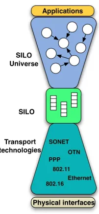
archi-Transport technologies
SILO
Ethernet OTN SONET
PPP 802.11 802.16
Applications
SILO Universe
Physical interfaces
Figure 2.1: The SILO Hourglass
tecture, the convergence point is the conformance to the meta-design, not a protocol (which is part of the design itself). Rather than a protocol upon and under which all else must be built, SILO offers the silo abstraction as an invariant, the narrow waist in the hourglass of this meta-design (Figure 2.1).
2.2
Basic Architecture
Figure 2.2 shows the difference between the SILO approach and the traditional networking stack. The traditional stack is shown in Figure 2.2 (a). There are multiple applications to which the transport layer provides sockets, but only a single instance of all other layers. This makes it impossible to provide customized service to different applications. For example, if we want to use reliable transport, we have to use the TCP/IP stack. It is quite hard to extract this functionality gracefully, while eliminating some other TCP functionality for some application that does not need it. Another downside of this traditional stack is that we cannot easily perform cross-layer tuning to optimize the stack; we have to write a custom version of layers for that purpose.
However, the SILO architecture incorporates these two requirements, as Figure 2.2 (b) demonstrates. The networking communication entity is dynamically composed of fine-grained functionalities, which we call services. The realization of services are calledmethods. m1,1,
Strategies
m1,1 m1,2 m2,1
m2,2 m4,1 m3,1
m3,1 m5,2 m6,3
m6,1 m6,1
Physical Channel Transport layer
Network layer
Link Control layer
Physical layer (a) Cross-Service Tuning Silo and Service Manage ment Ontology (b) App App Physical Channel
App App App
knobs
silo App
Figure 2.2: TCP/IP Stack vs. SILO Architecture
(knobs), which can be used byCross-Service Tuning for performance optimization according to Strategies. A stack of methods from an application to a physical channel, such as (m1,1,
m2,2, m3,1, m6,1), is called a silo1. Silo and Service Management composes silos with
constraints from Ontology. We explain these architectural components in greater detail next in the following several subsections.
2.2.1 Services
The fundamental building blocks in the SILO architecture are services. A service is a well-defined and self-contained function performed on application data, and it is relevant to a specific communication task. “In-order packet delivery,” “end-to-end flow control,” “packet fragmenta-tion,” “compression,” “encrypfragmenta-tion,” and “multi-rate RF PHY” are all examples of services in this context. Each service addresses a separate, atomic function; hence, the architecture pro-vides more flexibility and much finer granularity than current protocols that typically embed complex functionality.
At the core of the architecture is the mechanism through which services interact in order to accomplish complex communication tasks. Our approach represents a middle ground between the strict protocol stack imposed by current architectures and the “heap” approach advocated by the RBA [6]. Specifically, we allow any set of services to be selected dynamically for a particular task, but the order in which these services are applied is not tied to the “layer” in which the service belongs, but rather to a set of well-defined precedence constraints; for instance, when the application requires both a “compression” and an “encryption” service, the
1
only meaningful interaction is when compression is applied before encryption. In general, the precedence constraints impose a partial ordering among services. Once selected, however, the subset of services is arranged in a specific order, derived from the partial ordering and other rules, and this binding remains in effect for the duration of the associated communication task (typically, the lifetime of a connection).
A service is fully defined by describing: (1) the function it performs, (2) the interfaces it presents to other services, (3) any properties of the service that affect its relation with other services (e.g., as required to establish a partial ordering), and (4) its control parameters, which we also refer to as knobs (defined in 2.2.4) and their actions and constraints.
2.2.2 Methods
We distinguish between a service and its realization. A method is a realization of a service that uses a specific mechanism to carry out the functionality associated with the service. For instance, “re-sequencing” is one method for implementing the “in-order packet delivery” service, “window-based flow control” is a method for the “end-to-end flow control” service, and “802.11a OFDM PHY” is one method for the “multi-rate RF PHY” service. A method implementing a service must implement the service-specified interfaces, as well as any service-specific knobs; in other words, service-specific interfaces and knobs are polymorphic to all methods implementing a given service. A method may also implement method-specific knobs, i.e., control parameters unique to this implementation of a service; for instance, “length of Reed-Solomon FEC” is a knob specific to the “Reed-Solomon FEC” method implementing the “error-free delivery” service. These knobs are adjusted byCross-Service Tuning to refine the method behavior and to optimize it for a specific environment.
A method is fully defined by describing (1) the service it implements, (2) the specific algo-rithm/mechanism it uses to implement the service, and (3) the optional method-specific control parameters, and their actions and constraints. We emphasize that the architecture defines ser-vices and their interfaces, but it does not define the methods that implement them; therefore, it is possible that several alternative methods for a given service co-exist within the network.
2.2.3 Silo
Preceding Service Communication Spec
Service-specific Control Interface
Succeeding Service Communication Spec Service
Method
Service-Specific Controls
Preceding Service Communications
Method Implementation Method
Method-specific
Controls Succeeding Service Communications Service Knobs
Method Knobs
Figure 2.3: Service, Method and Knob
processing) of metadata to be included (respectively, present) in the packet. A silo possesses a state that is a union of all constituent method states, as well as any shared state resulting from cross-method interactions. A silo structure and all related state information are associated with a specific traffic stream (equivalently, a connection or flow), and they persist for the duration of the connection. One important aspect of silos is that they can be optimized for each traffic stream or for overall traffic stream, depending on the Strategies used by Cross-Service Tuning.
2.2.4 Knobs
The knobs include read/write knobs and read-only knobs. Alternatively, we call read/write knobs knobs, and read-only knobs gauges. The read/write knobs are adjustable parameters specific to the function performed by a service or a method, with a specified range of values or several enumerated values and a pre-defined relationship between these values and the perceived performance of the service or method. For instance, “compression factor” is a read/write knob for the “compression” service. The read-only knobs are values or states of a service or a method. For example, “throughput” is a read-only knob for the “performance monitor” service.
Figure 2.3 shows the relation between service, method and knob.
2.2.5 SILO Control
Cross-Service Tuning
Cross-Service Tuning is an architectural element that has the responsibility of adjusting all the service- and method-specific knobs and facilitating cross-service interactions in order to obtain the desired performance. Cross-Service Tuning makes use of Strategies to select appropriate tuning algorithms. The details of Cross-Service Tuning will be discussed in Chapter 4.
Silo and Service Management
Silo and Service Management manages the different elements of SILO architecture and has the responsibility of composing a silo for an application stream (or selecting an appropriate commonly-used silo). The services constraints are stored in Ontology, which is used by SILO management to determine the subset of services it contains, their order in the stack, and the method implementing each service. The objective is to dynamically custom-build a silo for each new connection. To this end, the Services and SILO Management takes into account the application’s QoS requirements, current network resource availability and other conditions, the precedence constraints among services, and any policy in effect at the time.
2.3
Comparisons with Similar Architectures
So far, we have presented all basic concepts of the SILO architecture. We summarize this chapter by comparing features of the SILO architecture with other composable architectures discussed in Section 1.3. Table 2.1 shows these feature comparisons.
Table 2.1: SILO Architecture vs. Other Composable Architectures
Name Granularity Minimal Unit Tuning Composability Customization SILO fine service cross-service
tun-ing
ontology-aided composition
application customized ontology or strategy F-CSS fine protocol
func-tion
only implied predefined compo-sition
application interfered network stack
x-kernel coarse protocol N/A static composition N/A Coyote fine composite
proto-col and micro-protocol
briefly mentioned, not architecturally enabled
composed of con-straints, not archi-tecturally enabled
N/A
RBA relatively small
role N/A small roles
com-pose a complex role
N/A
RNA N/A metaprotocol metaprotocol can be configured to different protocol
recursively com-pose of metaproto-col
Chapter 3
The SILO Software Prototype
We have developed a working prototype implementation that serves as a proof-of-concept demonstration of the feasibility of the SILO architecture, though we believe there are var-ious ways to implement SILO architecture, and there might be better ways. Our software prototype is detailed in this section, and we also explain our choices and reasonings.
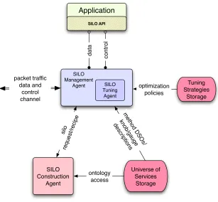
Our prototype software architecture (we also call it the SILO framework1) is shown in
Figure 3.1. The SILO framework consists of the following major components: • the SILO-enabled application (APP)
• the SILO API
• the SILO management agent (SMA)
• the SILO tuning agent (STA)
• the SILO construction agent (SCA)
• the SILO ontology of services and methods
• the universe of services storage (USS)
All the components shown in Figure 3.1 have been implemented. Firstly, we describe every component in Section 3.1. Then, we show how a silo is set up and interactions between com-ponents in detail in Section 3.3. Finally, we lay out implementation choices in Section 3.4 and software releases in 3.5.
SILO API
SILO Construction
Agent
Universe of Services
Storage SILO
Tuning Agent SILO
Management Agent
silo
request/recipe
ontology access
method DSOs/ knob/gauge descriptions data control
Tuning Strategies
Storage optimization
policies packet traffic
data and control channel
Application
Figure 3.1: SILO Prototype Architecture
3.1
Prototype Component Description
3.1.1 The SILO-Enabled Application
The SILO-enabled Application (APP) is any application that performs networking communica-tion through the SILO framework. This means the APP is linked against the SILO Applicacommunica-tion API and communicates with other SILO components through the SILO API. The APP could be a purpose-built application utilizing the SILO framework, or, alternatively, an existing net-worked application whose socket-based TCP/IP interface has been replaced with the SILO API or redirected to a SILO Application Gateway (details in Section 5.3.1).
3.1.2 The SILO API
The SILO API consists of C++ header files and library code. Two types of API and libraries are implemented:
• Application API - for creating SILO-enabled applications
inter-component communications)
Application API is exposed to applications. An application may call this set of APIs to request a silo, release a silo, send or receive data from a silo. Application API also allows applications to add application-specified constraints or ontology as part of the request.
Internal API is transparent to applications. The requests formed by applications are trans-ferred to SMA, then forwarded to SCA by SMA. We do not allow applications talking with SCA directly, simply because we would like to maintain a single channel between applications and the management components.
3.1.3 The SILO Management Agent
The SILO Management Agent (SMA) is the most important part of the prototype. It is mainly responsible for (a) constructing a silo for a specific application based on a recipe created by the SCA by loading services from the Universe of Services Storage into memories, (b) handling requests from SILO-enabled applications and returning silo handlers, and (c) maintaining the silo state during the communications session.
As stated before, the SMA uses an event-driven programming model. We chose the live 555 library [35] because it provides the friendly unix socket interfaces we need.
The construction of a silo involves instantiating the silo state, loading the necessary method code from the Universe of Services Storage and starting any required execution context.
3.1.4 The SILO Tuning Agent
In SILO release 0.1, the tuning agent was a separate process and tuning algorithms were stati-cally compiled together. Since the release of 0.2, the tuning agent has been integrated with the SMA and become part of it. The tuning algorithm is complied as a dynamically linked object and can be loaded by the tuning agent when necessary.
The change is based on the following reason. Although we can view the SILO Tuning Agent (STA) as a separate component from the SILO Management Agent conceptually, we do not need to develop another scaffold for the STA because the SMA already provides the perfect container to incorporate the STA functionalities. The STA is plugged into the SMA by setting scheduled events in the SMA.
The STA manipulates the knobs within individual silos in order to optimize its behavior according to a specific optimization goal. Optimization can be based on either individual or collective behavior of silos within a single node or among many nodes.
3.1.5 The SILO Construction Agent
The SILO Construction Agent (SCA) is also a major component of the architecture, and its responsibility is to give out a reasonable silo recipe based on the application’s request and composability constraints in Ontology.
The SCA only gives the recipe of a silo, represented in XML format. As mentioned before, the real construction work (loading services into the memory) is done by SMA. One might argue that some term like SILO Recipe Generator is a more proper name for this agent. However, we inherit this name from our initial architecture design as it was.
It could also be argued that we implement the SCA as a separate process, while integrating the STA as part of the SMA.
In SILO release 0.1, the SCA utilizes SILO Ontology, which is written in RDF. In order to access RDF by existing interfaces, we decided to use Jena, a set of Java API. So the first prototype was written in Java. We use TCP sockets to communicate between this Java-written SCA and the rest of the C++ written SILO components. That was the historical reason why the SCA and the SMA became separate processes.
In SILO release 0.2, we rewrote the SCA in Python, because Jena is a heavy library and we want to keep our release as light as possible. Besides, the original construction algorithm had various bugs, and it took less effort to rewrite the whole SCA than to debug the original algorithm. In the meantime, the rdflib python library provides friendlier and simpler interfaces to access RDF.
3.1.6 The SILO Ontology
One of the important challenges we encountered when addressing the problem of dynamically composable silos was related to the problem of representing the relationships (composability constraints) between the various services and modules. Essentially, this is a problem of knowl-edge representation. These composability constraints take the form of statements similar to “Service A requires Service B” or “Service A cannot coexist with Service B,” which can be modulated by additional specifications such as ‘above’ or ‘below’ or ‘immediately above’ or ‘im-mediately below.’ Additionally, we needed to deal with the problem of specifying application preferences or requests for silos, which can be described as application-specific composabil-ity constraints. To address this problem, we turned to ontologies, specifically, ontology tools developed by the semantic Web community.
Relying on RDF-XML syntax, we were able to create a schema defining various possible relationships between the elements of the SILO architecture, namely, services and methods. These relationships include the aforementioned composability constraints, which can be com-bined into complex expressions using conjunction, disjunction and negation. Using this schema, we have defined a sample ontology for the services we implemented in the current prototype. The application constraints/requests are expressed using the same schema. This uniform ap-proach to describing both application requests as well as the SILO ontology is advantageous in that a request, issued by the application and expressed in RDF-XML, can be merged into the SILO ontology to create a new ontology with two sets of constraints – the original SILO constraints and those expressed by the application, on which the composition algorithm then operates. Using existing semantic Web tools, we have implemented several composition algo-rithms [39] that operate on these ontologies and create silo recipes, from which silos can be instantiated.
Our RDF schema also allows us to express other knowledge, such as the functions of ser-vices (an example of a service function could be “congestion control” or “error correction” or “reliable delivery”), as well as their data effects (examples include cloning of a buffer, splitting or combining of buffers, transformation, and finally null, which implies no data effect). These are intended to aid composition algorithms in deciding the set of services to be included in a silo, when an application is unable to provide precise specifications in the request. Using this additional information in the composition algorithm is an active area of our research.
For more information about the SILO Ontology and the decreased Java Construct Agent, please refer to [39, 40].
3.1.7 SILO Services
Silo services are the fundamental building blocks, as presented in Section 2.2.1. A SILO service exists as a Linux shared-object (*.so) file. Like other dynamic linked libraries, such as a DLL in Windows, it can be loaded to the memory by the SMA when it is needed.
More details about designing SILO services are presented in Section5.1.
3.1.8 SILO Tuning Algorithms and Tuning Strategies Storage
A tuning algorithm is a Linux shared-object (*.so) file. It can be loaded to tune the performance of a silo or a set of silos by the SILO Tuning Agent. The Tuning Strategies Storage (TSS) serves as the repository of tuning algorithms for the STA and can be viewed as part of the USS.
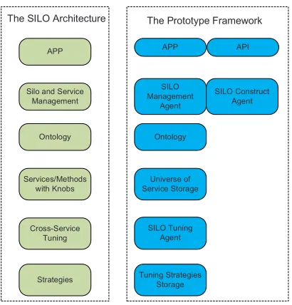
The SILO Architecture
APP
Silo and Service Management
Services/Methods with Knobs
Ontology
Cross-Service Tuning
Strategies
APP API
SILO Management
Agent
SILO Construct Agent
Ontology
Universe of Service Storage
Tuning Strategies Storage SILO Tuning
Agent
The Prototype Framework
Figure 3.2: SILO Architecture Components vs. Prototype Framework Components
3.1.9 Universe of Services Storage
The USS serves as the main repository of information about the SILO framework. It contains (a) silo services, (b) tuning algorithms, (c) the ontology that describes relationships between services and service interfaces, (d) a database of method implementations that helps the SMA locate the executable code necessary to construct a given silo, and (e) current policy setting that affects the operation of the SILO framework. These can be application-, node- and network-specific.
Silo services and tuning algorithms are presented as *.so files in the USS. Ontology is presented in the format of RDF and RDFS in USS. We chose to implement (d) as an XML file. We call it silo universe.xml. (e) is our vision and is not implemented in the current prototype.
3.2
Mapping the Prototype Framework to the SILO
Architec-ture
3.3
Silo Setup Procedure and Component Interactions
In this section, we present how the prototype framework responds an application request and compose a silo for it. We also explain component interactions along this procedure.
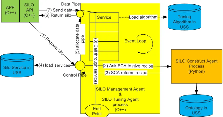
SILO Management Agent &
SILO Tuning Agent process
(C++)
Event Loop APP
(C++)
Silo Service in USS
Service
SILO Construct Agent Process (Python) SILO API (C++) (1 ) R eque st s ilo
(2) Ask SCA to give recipe (3) SCA returns recipe
(5 ) a llo c a te d a ta p ip e
(6) Return silo
(4) load services (7) Send data
(8 ) C a ll th ro u g h s e rv ic e s End Point Control Pipe Data Pipe Ontology in USS Tuning Algorithm in USS Load algorithm
Figure 3.3: Silo Setup Procedure
The procedure is also shown in Figure 3.3. Please follow the sequence number in the diagram.
(1) The application utilizes SILO Application API to create a request, which may include application-customized constraints. This request is forwarded to the SMA by the SILO API through a control pipe in the SMA.
(2) Then the SMA consults with the SCA to validate the request. The communication between the SCA and the SMA is done by Unix sockets.
(3) The SCA validates the request according to the ontology in USS. If the request is valid, the SCA gives a final recipe with a sequence of service names to the SMA.
(4) The SMA uses the returned recipe and silo universe.xml described in Section 3.1.9 to load service (*.so) files into the memory, keeps the states of every service,
(6) and returns the reference of the newly created silo as a silo handler to the application through SILO application API. The STA could possibly load tuning algorithms from the TSS/USS.
(7) After the application has the proper silo handler, data could be sent to the SMA through the data pipe. Then SMA calls functions in every service to process data. The data exit the SILO framework through the endpoint.
3.3.1 SILO Endpoint
The SILO Endpoint (we may simply refer it as endpoint) is a very important concept we discover when we develop the prototype framework. We envision the SILO architecture as a silo starting from an application and ending at the other end of the silo with the other application. However, for practical reasons, we need to determine where a silo ends in the SILO prototype framework. This is where exactly endpoint is.
Endpoint is where a silo ends, and it is the boundary between the SILO framework and the outside world. As a silo could be bi-directional, technically, an endpoint is also where a silo starts. From this perspective, an application endpoint is needed to connect a silo to an application.
Through endpoints, the SILO prototype framework hands over the control of data to the operating system. Endpoints also collect data and hand the data back to the SILO prototype framework in the opposite direction of the dataflow.
In our current release 0.3, we support two types of endpoints: the UNIX socket endpoint and the UDP endpoint. An application endpoint is a special type of the UNIX socket endpoint.
3.4
Several Implementation Choices
We chose C++ as our main programming language because an object-oriented language fits our architecture design, and C++ can access system resources more freely than Java.
We chose to implement the prototype in the Linux user space because we are focusing on validating the basic architecture concepts and trying to avoid the complexity of kernel space. If it becomes necessary, we may port all the components to the kernel space.
Table 3.1: Source Lines of the SILO Code
Language Files Comment Code
C++ 70 1,991 12,125
C++ Header 65 1,061 2,991
XML/RDF/RDFS 15 18 1,951
Python 1 174 466
C 1 15 259
Shell Script 16 23 185
Scons/make 12 42 176
Sum 180 3,324 18,153
and give detailed instructions for installing SILO on them in the “SILO User’s Guide,” which has been released along with the prototype and also appended as Appendix A.
The main component of the prototype, SMA, is an event-driven, not multi-thread program. The greatest advantage we have with the event-driven model is full control of the program in terms of scheduling, which is important when we want to control data flows precisely. The event-driven model also makes it easier to assemble several components while not worrying about synchronization of the components. We do not argue that the event-driven model is necessarily better than the multi-thread model for this prototype, but we chose the former based on the reasons outlined above.
3.5
Software Releases
Since early 2007, we have put much effort into designing the architecture and developing the prototype. There are also six branches dedicated to CSC570, NSF Demo, Virtualization and VCAT extension, TCP-like silo, and IMF. As of today (08/2010), there are 180 files, 18,153 lines of code and 156 defined C++ classes with 670 methods in the IMF branch. Table 3.1 shows the physical source lines of code using cloc [41]. These lines exclude blank lines.
On 05/02/2008, we released prototype version 0.1. Most of the software components in-cluding SMA, SILO API, and Silo Universe were released at that time. A service testing tool was also released, allowing developers to plug in their services into the framework easily.
On 09/25/2008, we released prototype version 0.2. The main changes from 0.1 include mul-tiple bug fixes in the SMA; inclusion of a working tuning agent and sample tuning algorithms; and a working Silo Construct Agent re-written in Python. So far, all defined SILO components have been released.
extensions for IMF. This release also features the updated users’ guide and the service and tuning algorithm programming guide. The current release is available for downloading at the SILO official Web site [42].
Chapter 4
Architectural Enabling of
Cross-Service Tuning
In this chapter, we explore how we enable Cross-service Tuning in the SILO architecture. We investigate the motivation of Cross-service Tuning in Section 4.1. Then, we explain how we designed the SILO Tuning Agent, knobs and tuning algorithms to enable Cross-service Tuning in Section 4.2. Several tuning algorithms are presented in Section 4.3, and the experimental setup and results are given in Section 4.4.
4.1
Motivation: From Cross-Layer to Cross-Service
The concept of knobs for services and methods side-steps these problems. The SILO archi-tecture can be viewed as “operate in layers, control across layers.” As of today, services and methods are required only to provide a minimal interface, hiding internal details. However, traditional protocols are only required to provide invocation methods (APIs), whereas in the SILO architecture, we require them to provide a minimal control interface as well. Beyond this, the methods can be designed and implemented in isolation, as before. However, the tuning agent has a unique view of the knobs of every method in the silo and can embody all the inte-grated control concerns. In this way, “cross-service” (the antonym to “cross-layer” in the SILO universe) can become part of the mainstream architecture.
4.2
Realization
In the SILO prototype (Figure 3.1), we introduce the SILO Tuning Agent (STA) primarily to perform cross-service tuning, as envisioned in the SILO architecture. From the perspective of software, cross-service tuning includes services/methods and their tunable knobs, measurement services/methods and their gauges/read-only knobs, loadable tuning algorithms, and STA. In this section, we present how we implement it by describing how we design knobs and STA.
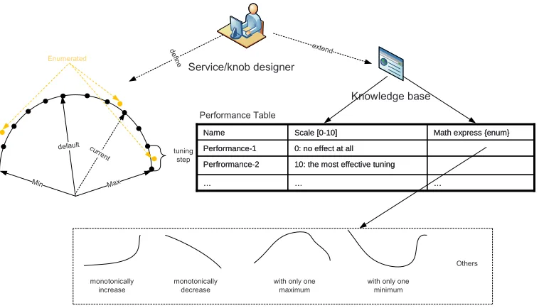
4.2.1 Design of Knobs
As Figure 2.2 (b) shows, services and methods include tunable interfaces called knobs. However, SILO architecture, or even our prototype framework, does not limit a particular way to design or implement knobs.
This section shows our detailed knob design. We consider the following factors in our designs:
(1) Exposable: Easily expose services’ or methods’ interfaces; (2) Tunable: Easily tuned by tuning algorithms; and
(3) Presentable: Easily presented as an understandable form to the tuning agent.
Min Max default curr ent tuning step Enumerated monotonically increase monotonically decrease
with only one maximum
with only one minimum Knowledge base Service/knob designer … … …
10: the most effective tuning Perfrormance-2
0: no effect at all Performance-1
Math express {enum} Scale [0-10]
Name
… …
…
10: the most effective tuning Perfrormance-2
0: no effect at all Performance-1
Math express {enum} Scale [0-10]
Name
Others Performance Table
de
fine extend
Figure 4.1: SILO Knobs
Compared to a read-write knob, a read-only knob/guage is fairly simple and just provides a current value.
Envisioning Knobs
We also envision certain ways to help expedite the tuning process, although these features are not implemented in the current prototype.
As shown in the right part of Figure 4.1, in addition to the basic properties of a knob, the service/knob developer may provide certain knowledge, such as a performance table. The performance table reveals the correlation between knobs and performances in terms of scales and tuning effects. Some tuning effects can be expressed mathematically.
With the help of this extra knowledge, a proper set of knobs can be more easily selected to reach certain performance optimization. Using a known, mathematically expressed tuning effect may significantly expedite the entire tuning process.
4.2.2 Design of SILO Tuning Agent
SILO Tuning Agent
SILO Management
Agent Tuning Strategies Storage
Algorithm 1
Algorithm 2 Algorithm 3
m1,1
m2,2
m3,1
m6,1
Communicate information about silos and knobs Load/unload algorithms
Tune knobs on behalf of algorithms
Performance Measurement Service
Figure 4.2: SILO Tuning Agent
adjusting the knobs. The selection of an appropriate control strategy is governed by policies stored within the tuning strategies storage.
Figure 4.2 shows the main responsibilities of the SILO Tuning Agent. The STA loads or unloads tuning algorithms from the Tuning Strategies Storage into the memory; it asks the SMA to pass necessary information in order to enable tuning algorithms, such as a list of silos running in the system and a list of knobs a service/method possesses; it tunes the knobs on behalf of tuning algorithms; it reads back performance measurement from read-only knobs/gauges on performance measurement services, and passes it to tuning algorithms.
4.2.3 Design of Tuning Algorithms
The tuning algorithms are compiled as dynamic link files (*.so files in Linux) and stored in the Tuning Strategies Storage. They can be loaded into the memory by the STA.
A tuning algorithm can be roughly divided into three parts, as follows:
Controller - Asks the STA to tune knobs in a particular way;
Synthesis Rules - Collects performance measurements and decides the overall performance; and
Set Point - Starts or stops the controller when a certain performance level is desired or reached.
4.2.4 Design of Measurement Services
A measurement service is a critical piece in the SILO tuning system. It provides performance in-formation through its read-only knobs or gauges. Some examples of performance measurements are bit error rate, bit per seconds, packet counts, or throughput, etc.
Designing a measurement service is no different from designing other SILO services. The details of designing SILO services are presented in Section5.1.
As the SILO architecture does not specifically define measurement, we investigate the inte-gration of the SILO architecture and the Intergraded Measurement Framework in Chapter8.
4.2.5 Recapping the SILO Cross-Service Tuning
As a summary, the SILO Cross-Service Tuning is enabled by the coordination of the following components: knobs, the SILO Tuning Agent, tuning algorithms, and measurement services.
From the perspective of control theory, the SILO Cross-Service Tuning is a self-tuning, closed-loop control system. It equips four basic concepts of a typical self-tuning system: expec-tation, measurement, analysis, and action.
4.2.6 Envisioning Cross-Service Tuning
Besides what we have enabled, we also envision certain advanced features and extensions of Cross-Service Tuning, although they are not implemented in the current prototype framework. Figure 4.3 shows our grand vision.
Cross-Node Tuning Cross-node tuning expands the cross-service tuning from within a sin-gle node to multiple nodes. With a better understanding of the network, STAs are able to provide more precise tuning. After the silo connection is set up, the STA in the local node can communicate and coordinate with the STA in the remote node along with STAs in the path between the local node and the remote node. SYNC in Figure 4.3 refers to the crossing-node tuning synchronization and to the coordination between the local node and the remote node. Cross-node tuning also could take into consideration the disturbance from other silos in the Internet along the data flow path.
![Figure 1.2: F-CSS Architecture (adapted from [17])](https://thumb-us.123doks.com/thumbv2/123dok_us/1701163.1215710/17.612.113.511.327.556/figure-f-css-architecture-adapted-from.webp)