Scholarship@Western
Scholarship@Western
Electronic Thesis and Dissertation Repository
12-13-2013 12:00 AM
InterNAV3D: A Navigation Tool for Robot-Assisted Needle-Based
InterNAV3D: A Navigation Tool for Robot-Assisted Needle-Based
Intervention for the Lung
Intervention for the Lung
Srikanth Bhattad
The University of Western Ontario
Supervisor Dr. Rajni Patel
The University of Western Ontario
Graduate Program in Electrical and Computer Engineering
A thesis submitted in partial fulfillment of the requirements for the degree in Master of Engineering Science
© Srikanth Bhattad 2013
Follow this and additional works at: https://ir.lib.uwo.ca/etd
Part of the Biomedical Commons, and the Other Electrical and Computer Engineering Commons
Recommended Citation Recommended Citation
Bhattad, Srikanth, "InterNAV3D: A Navigation Tool for Robot-Assisted Needle-Based Intervention for the Lung" (2013). Electronic Thesis and Dissertation Repository. 1760.
https://ir.lib.uwo.ca/etd/1760
This Dissertation/Thesis is brought to you for free and open access by Scholarship@Western. It has been accepted for inclusion in Electronic Thesis and Dissertation Repository by an authorized administrator of
(Thesis format: Monograph)
by
Srikanth Omprakash Bhattad
Graduate Program in Department of Electrical and Computer Engineering
A thesis submitted in partial fulfillment of the requirements for the degree of
Master of Engineering Science
The School of Graduate and Postdoctoral Studies The University of Western Ontario
London, Ontario, Canada
ii
Abstract
Lung cancer is one of the leading causes of cancer deaths in North America. There are recent
advances in cancer treatment techniques that can treat cancerous tumors, but require a
real-time imaging modality to provide intraoperative assistive feedback. Ultrasound (US) imaging
is one such modality. However, while its application to the lungs has been limited because of
the deterioration of US image quality (due to the presence of air in the lungs); recent work
has shown that appropriate lung deflation can help to improve the quality sufficiently to
enable intraoperative, US-guided robotics-assisted techniques to be used. The work described
in this thesis focuses on this approach.
The thesis describes a project undertaken at Canadian Surgical Technologies and
Advanced Robotics (CSTAR) that utilizes the image processing techniques to further
enhance US images and implements an advanced 3D virtual visualization software approach.
The application considered is that for minimally invasive lung cancer treatment using
procedures such as brachytherapy and microwave ablation while taking advantage of the
accuracy and teleoperation capabilities of surgical robots, to gain higher dexterity and precise
control over the therapy tools (needles and probes). A number of modules and widgets are
developed and explained which improve the visibility of the physical features of interest in
the treatment and help the clinician to have more reliable and accurate control of the
treatment. Finally the developed tools are validated with extensive experimental evaluations
and future developments are suggested to enhance the scope of the applications.
Keywords
Lung cancer, tumor, brachytherapy, microwave ablation, radiofrequency ablation, VTK, ITK,
image processing, 3D visualization, virtual reality, needle maneuvering, needle bending,
needle tip detection, needle retraction, image guided intervention, medical imaging,
iii
Acknowledgments
I am very grateful to all the people that helped me achieve this goal. Firstly, I would like to
thank my supervisor Dr. Rajni Patel for giving me an opportunity to work in CSTAR and for
his constant guidance, encouragement and support during my thesis work. I would also like
to thank Dr. Malthaner for all the talks he had with me and for helping me carry out
experiments from time to time.
I would like to thank all my friends and colleagues at CSTAR, especially Abe, Chris and Ran
for being such a wonderful team to work with and for their constant source of help and
inspiration, their support and those lengthy discussions without which things would be little
tougher.
I would also like to thank my family members for standing by me all these years, patiently
supporting me in my endeavor to achieve success and happiness.
Lastly, I would like to thank Mathworks, the developers of the open source project: VTK and
ITK, and all the people who contributed in getting so many wonderful tools in the hands of
students; providing them the required momentum in developing the applications for carrying
iv
Table of Contents
Abstract ... ii
Acknowledgments ... iii
Table of Contents ... iv
List of Tables ... vii
List of Figures ... viii
List of Appendices ... xv
List of Abbreviations ... xvi
Chapter 1 ... 1
1 Introduction ... 1
1.1 Cancer overview ... 1
1.2 Lung cancer statistics ... 3
1.3 Types of lung cancer ... 4
1.4 Treatment ... 5
1.4.1 Conventional treatment approach ... 5
1.4.2 Minimally invasive intervention ... 6
1.4.3 Current scenario ... 12
1.5 Image-guided intervention ... 14
1.6 Robot-assisted minimally invasive surgery ... 15
1.7 InterNAV ... 16
1.8 Thesis contribution... 19
1.9 Thesis outline ... 21
Chapter 2 ... 22
2 System Architecture: Hardware and Software ... 22
v
2.3 System components ... 28
2.3.1 Hardware components ... 28
2.3.2 Software components ... 43
Chapter 3 ... 49
3 User Interface: Modules and Working ... 49
3.1 User interface ... 52
3.1.1 Right dock ... 52
3.1.2 Left dock ... 54
3.1.3 Top dock (toolbar menu) ... 67
3.1.4 Bottom dock (system log) ... 67
3.2 Modules and working ... 68
3.2.1 Virtual needle and path projection ... 68
3.2.2 Current needle path visualization ... 71
3.2.3 Needle path prediction ... 72
3.2.4 Virtual US probe and the real-time 2D US image ... 74
3.2.5 US video output window, target selection and visualization ... 77
3.2.6 Volume rendering and opacity transfer... 78
3.2.7 Surface rendering and sub-surface reconstruction ... 80
3.2.8 Region reconstruction ... 83
3.2.9 Motion simulation ... 84
3.2.10 Needle navigation ... 84
3.2.11 Camera movements and additional windows ... 85
3.3 Remarks ... 87
Chapter 4 ... 88
vi
4.1.1 Motion induction ... 91
4.2 Calibration... 97
4.2.1 Needle tool tip calibration ... 97
4.2.2 US image calibration... 100
4.2.3 Robotic calibration ... 104
4.3 Experiments and validations ... 108
4.3.1 Needle bending ... 110
4.3.2 Needle maneuvering ... 113
4.3.3 Tumor detection and reconstruction ... 117
4.3.4 Ex-vivo experiments: target selection and hitting ... 119
4.3.5 Needle retraction ... 126
4.3.6 In-vivo experiments ... 127
4.4 Review ... 133
Chapter 5 ... 134
5 Summary, Conclusion and Future Work ... 134
5.1 Summary ... 134
5.2 Conclusion ... 138
5.3 Drawbacks and future work ... 140
Bibliography ... 143
Appendix A: Manufactured parts ... 156
vii
List of Tables
Table 1.1: Lung cancer statistics (Canada) ... 4
Table 2.1: 5-DOF sensor accuracy ... 35
Table 2.2: 6-DOF sensor accuracy ... 35
Table 4.1: US image calibration value ... 104
Table 4.2: Evaluating the calibration ... 108
Table 4.3: Error analysis (needle tip detection) ... 112
Table 4.4: Needle maneuvering experimental analysis ... 116
Table 4.5: Error analysis (3D volume reconstruction)... 119
Table 4.6: Error analysis for needle target hitting ... 125
Table 4.7: Number of insertion attempts to reach the target ... 125
viii
List of Figures
Figure 1.1: Cancer – a leading cause of death (Canada)... 1
Figure 1.2: Death by cancer type ... 2
Figure 1.3: Percentage distribution of estimated cancer deaths (2013) ... 3
Figure 1.4: Brachytherapy ... 7
Figure 1.5: Brachytherapy seeds ... 8
Figure 1.6: Brachytherapy needles and stylets of different gauge size... 9
Figure 1.7: Radiofrequency ablation... 10
Figure 1.8: Radiofrequency ablation probes ... 11
Figure 1.9: Microwave ablation probes ... 11
Figure 1.10: Image guided intervention platform ... 15
Figure 1.11: InterNAV setup for lung brachytherapy ... 17
Figure 1.12: InterNAV user interface ... 17
Figure 2.1: System overview and working ... 23
Figure 2.2: Flowchart for system initialization and working ... 25
Figure 2.3: Ultrosonix’s Sonixtouch US machine ... 28
Figure 2.4: Laparoscopic probe used ... 29
Figure 2.5: US probe bent from the flexible part ... 30
Figure 2.6: US probe enclosed in a sleeve ... 30
ix
Figure 2.9: NDI’s Aurora electromagnetic tracker system ... 32
Figure 2.10: Field generator and the Cartesian co-ordinate space ... 33
Figure 2.11: 5-DOF sensor ... 34
Figure 2.12: 6-DOF sensor ... 34
Figure 2.13: Roll, pitch and yaw ... 36
Figure 2.14: Bevel-tip needle with 5-DOF sensor enclosed ... 36
Figure 2.15: Sleeve for radiofrequency ablation probe with the channel for EM tracking sensor ... 37
Figure 2.16: radiofrequency ablation probe with sensor attached to sleeve ... 37
Figure 2.17: Microwave ablation tool with sleeve and sensor attached ... 37
Figure 2.18: US probe with electromagnetic sensor attached using shrink wrap ... 38
Figure 2.19: US probe with the attached sleeve ... 38
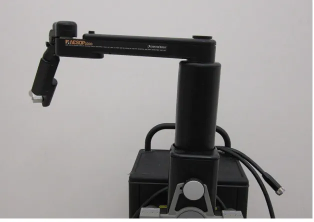
Figure 2.20: AESOP robot ... 39
Figure 2.21: Remote workstation for ZEUS robotic system ... 40
Figure 2.22: ZEUS robotic setup ... 40
Figure 2.23: AESOP/ZEUS kinematic model ... 41
Figure 2.24: Kinematic model superimposed ... 41
Figure 2.25: Matrox frame grabber ... 42
Figure 2.26: Software architecture ... 43
x
Figure 3.1: User interface ... 51
Figure 3.2: Dock areas for the GUI interface ... 52
Figure 3.3: VTK window (3D virtual world)-multiple volumes ... 53
Figure 3.4: Typical VTK window ... 54
Figure 3.5: US real-time video stream ... 54
Figure 3.6: Control panel ... 55
Figure 3.7: System control ... 56
Figure 3.8: Pop-up menu... 56
Figure 3.9: Sweep control ... 57
Figure 3.10: Round sweep ... 57
Figure 3.11: Flat sweep (straight sweep) mode ... 58
Figure 3.12: Multiple ablation volumes at different time intervals ... 61
Figure 3.13: Volume subtraction ... 63
Figure 3.14: Status panel... 63
Figure 3.15: Movement control panel ... 64
Figure 3.16: Visualization control ... 65
Figure 3.17: Surface control ... 65
Figure 3.18: Surface opacity control ... 66
xi
Figure 3.21: System log ... 67
Figure 3.22: Needle path projection ... 68
Figure 3.23: Needle updated path projection ... 69
Figure 3.24: Needle STL superimposed on the US image... 70
Figure 3.25: Current needle path ... 71
Figure 3.26: Needle path prediction ... 72
Figure 3.27: Needle path prediction with the current needle path ... 73
Figure 3.28: US probe and the 2D US image rendered in 3D space ... 74
Figure 3.29: US image superimposed on a volume ... 75
Figure 3.30: Image capture model ... 76
Figure 3.31: Target selection and visualization ... 77
Figure 3.32: Opacity transfer function ... 79
Figure 3.33: Surface reconstruction ... 80
Figure 3.34: Surface reconstruction superimposed over volume ... 81
Figure 3.35: Sub-surface reconstruction ... 82
Figure 3.36: Region reconstruction... 83
Figure 3.37: Needle eye view ... 85
Figure 3.38: Three orthogonal views ... 86
xii
Figure 4.2: Ball and socket joint (attached) ... 89
Figure 4.3: Linear stage ... 89
Figure 4.4: Entire test-bed... 90
Figure 4.5: Air pump mechanism ... 91
Figure 4.6: Motion inducing system ... 92
Figure 4.7: Rotational sweep capture model... 93
Figure 4.8 Scatter plot for 2D to 3D image conversion ... 97
Figure 4.9: Pivot tool-tip calibration ... 98
Figure 4.10: Needle tip calibration ... 99
Figure 4.11: Pivot calibration values ... 99
Figure 4.12: US image plane calibration ... 101
Figure 4.13: Calculating dataset transformation ... 102
Figure 4.14: Phantoms used to evaluate calibrations ... 106
Figure 4.15: Evaluating the calibration using a phantom ... 107
Figure 4.16: Phantom volume and surface reconstruction ... 107
Figure 4.17: Needle with two 5-DOF sensors attached ... 110
Figure 4.18: Experimental setup for evaluating needle bending ... 111
Figure 4.19: Needle bending visualization and tip detection in the 3D virtual world ... 112
xiii
in modules (displayed within the boxes) ... 115
Figure 4.22: Re-orientation during an insertion procedure with the assistance of the built-in modules (displayed within the boxes)... 115
Figure 4.23: Agar sphere being imaged ... 117
Figure 4.24: Experimental setup for 3D volume reconstruction ... 118
Figure 4.25: 3D volume and surface reconstruction ... 118
Figure 4.26: Ex-vivo experiment ... 120
Figure 4.27: Phantom tumors ... 121
Figure 4.28: Tissue sutured after implanting tumors and being imaged by US ... 121
Figure 4.29: Seed missed the target using InterNAV ... 122
Figure 4.30: Electromagnetic tracker attached to the phantom tumor ... 123
Figure 4.31: Volume reconstruction of duck gizzard ... 124
Figure 4.32: Needle insertion and retraction path ... 127
Figure 4.33: Phantom tumor with the attached electromagnetic tracker placed within the lung and sutured ... 128
Figure 4.34: 3D reconstructed volume... 129
Figure 4.35: In-vivo 2D US image of the deflated lung ... 129
Figure 4.36: In-vivo lung experiment (needle hitting the target) ... 130
Figure 4.37: In-vivo thermal ablation (power 30W, microwave energy) ... 131
Figure 4.38: Ablation volume ... 131
xiv
Figure A.1: US probe holder ... 156
Figure A.2: Test-bed assembly ... 157
Figure A.3: Ball and socket design ... 157
Figure A.4: Microwave ablation probe holder ... 158
Figure A.5: Radiofrequency ablation probe holder ... 158
xv
List of Appendices
xvi
List of Abbreviations
2D Two dimensional
3D Three dimensional
AESOP Automated Endoscopic System for Optimal Positioning
API Application Programming Interface
CISST Computer Integrated Surgical Systems and Technology
CPU Central Processing Unit
CSTAR Canadian Surgical Technologies & Advanced Robotics
CT Computed Tomography
DDR3 Double Data Rate type three
DOF Degrees of Freedom
FDA Food and Drug Administration
GB Giga Byte
GHz Giga Hertz
GUI Graphical User Interface
HDR High Dose Rate
ID Identification Data
IDE Integrated Development Environment
InterNAV Interventional Navigation
xvii
MIL Matrox Imaging Library
MRI Magnetic Resonance Imaging
NDI Northern Digital Incorporated
OpenIGTLink Open Network Interface for Image-Guided Therapy
PCI Peripheral Component Interconnect
RAM Random Access Memory
RMS Root Mean Square
ROS Robot Operating System
SAW Surgical Assistant Workstation
STL Stereo Lithography
Tcl/Tk Tool Command Language
TM Trade Mark
URI Ultrasound Research Interface
US Ultrasound
Chapter 1
1
Introduction
This chapter provides the background and motivation for the project, a literature review
of the recent technologies, their operation and a brief overview of the previous version of
the system. At the end, it outlines the contribution of the thesis in the context of the
research project.
1.1
Cancer overview
Cancer is a disease that is a result of uncontrolled growth of cells. Cancerous cells further
divide to form lumps of tissue referred to as tumors. Cancer can grow in almost any
tissue or organ of the body. It needs to be controlled or else it can migrate to other
healthy parts of the body causing a greater risk to the life of the patient. Lung cancer is
one of the most prominent forms of cancer diagnosed today. Proper medical treatment is
advised as early as possible to control the growth of cancerous tumors and destroy or
resect them.
This section summarizes the data obtained from Canadian Cancer Statistics, 2013
[1]. It gives an overview of the cancer deaths in Canada. Most of the information and
statistical data are projected estimations.
From Figure 1.1, the percentage of total deaths due to cancer for year 2009 was
around 29.8 % in Canada. It is projected that in 2013, around 187,600 Canadians will be
diagnosed with cancer and around 75,500 would die from it (approximately 27 % of total
deaths in Canada). The following pie chart distinguishes between the cancer deaths
estimated for the year 2013. An estimated 57% of total cancer deaths would occur due to
lung (27%), colon (12%), breast (7%), pancreas (6%) and prostate (5%) cancer.
Figure 1.2: Death by cancer type
Figure 1.3 lists the percentage distribution of cancer deaths by sex estimated for
year 2013. Lung cancer is the most prominent cancer, causing deaths in both males and
Figure 1.3: Percentage distribution of estimated cancer deaths (2013)
1.2
Lung cancer statistics
For 2013, around 25,500 Canadians would be diagnosed with lung cancer and around
20,200 would die of it. By the estimation provided, for every 1000 deaths (due to any
Table 1.1: Lung cancer statistics (Canada)
Category Males Females
New Cases 13,300 12,200
Incidence rate (for every 100,000 people) 60 47
Deaths 10,700 9,500
Death rate (for every 100,000 people) 48 36
5-year relative survival (estimates for 2006-2008) 14% 20%
A major cause of lung cancer can be attributed to the cigarette smoking [1]. It is
estimated that around 90% of lung cancers are caused by it, with factors such as intensity
and duration of smoking playing a significant role in the incidence of the disease. The
lifetime probability of dying from lung cancer is the highest among all forms of cancer. It
is therefore of utmost importance to find suitable and viable techniques which could
improve the current state of lung cancer treatment; and to make the whole process less
traumatic for patients and easy to be performed by clinicians.
1.3
Types of lung cancer
Lung cancer is usually distinguished as either small cell lung cancer or non-small cell
lung cancer depending on the size of the cancerous cells. Small cell lung cancer is highly
attributed to smoking. This cancer grows rapidly in the course of the disease and has a
tendency to spread quickly to other parts of the body. The non-small cell lung cancer on
the other hand, spreads comparatively slowly. Depending on the type of the cancer
diagnosed, appropriate treatment techniques are suggested to the patient. Needle biopsy,
bronchoscopy, X-ray, CT scan, US etc. are some of the procedures most commonly used
1.4
Treatment
This section mainly concentrates on conventional surgical and minimally invasive
techniques for lung cancer treatment, their comparison in terms of advantages and
drawbacks followed by current scenarios for treatment.
Surgical resection remains the primary treatment method for patients diagnosed
with early-stage lung cancer. The cancerous part of the lung is completely removed by
cutting out a small section (wedge resection), an entire lobe (lobectomy) or an entire lung
(pneumonectomy) depending on the extent of the cancer. This type of surgery is more
invasive because large incisions are made in the body so as to remove the tumor. It
causes a lot of trauma to the patient. Some patients may not be considered fit to undergo
such a procedure depending on their health and age. Considering this, a number of other
treatment techniques such as chemotherapy, brachytherapy [2]–[5], external beam
therapy [6], [7] thermal ablation therapy [8]–[10], cryotherapy [11], [12] etc. are
suggested.
1.4.1 Conventional treatment approach
In this approach, usually surgical resection is applied to remove the tumor followed by
chemotherapy and/or external beam radiation therapy. This is a very common approach
for most of the malignant tumors formed in different organs such as lung, liver, prostate,
breast, etc. Photodynamic therapy is also a new technique that can be used to treat cancer.
Wedge resection is a treatment where a small wedge shaped part of the lung is
removed surgically which is infected by cancerous tissue. It is easy to recover and does
not greatly affect the shape of lung. In lobectomy an entire lobe of the lung is resected. It
is usually performed in early stage non-small cell lung cancer patients; whereas
pneumonectomy consists of removal of a complete lung (patients are first diagnosed for
their capacity to be able to breathe using just one lung). This kind of treatment is done
very rarely and in only critical cases where a major portion of the lung is severely
affected by cancer. The breathing capacity of the patient is reduced significantly post
Chemotherapy is the use of cytotoxic medication to kill cancerous cells as they
are more prone to this kind of medication due to their tendency of dividing rapidly. It is a
systematic treatment meaning that it can be used to kill the malignant cells in any part of
the body as compared to radiation therapy which is a localized treatment method. Small
cell lung cancer is usually treated with this therapy as this type of cancer has a tendency
to spread faster. The therapy has side effects of hair loss, nausea and low blood cell
counts.
External beam radiation therapy is a method of treatment where high energy
radiation is used to kill cancerous tissue. An external machine is used to transfer the
energy at the particular marked area of the body which overlies the tumor. There are
other types of radiation therapies such as internal radiation therapy (brachytherapy)
which will be discussed in a later section.
Cryotherapy is another way to treat cancer. It is mostly used as a localized cancer
treatment where a probe (cryoprobe) is used to deliver extreme cold temperatures to the
cancerous tissue so as to freeze and kill the underlying cancer cells. Image guidance is
used to drive the probe to the target. Cryoprobe is inserted in a body through a
bronchoscope or percutaneously (thus, it can also be considered as a minimally invasive
intervention technique).
Photodynamic therapy [13], [14] consists of a patient being injected by special
photosensitizing drug which gets absorbed by the body cells. The cancerous cells
however retain them longer as compared to normal cells. The cancerous cells (now
sensitive to light) are subjected to external light source which is passed through a
bronchoscope. The light triggers the drug, destroying the cancerous cells.
1.4.2 Minimally invasive intervention
This is a relatively new type of interventional technique where small incisions about 1cm
across are made in the body which act as access ports for laparoscopic instruments to
enable them to reach the surgical site. Benefits of this technique are reduced trauma to the
1.4.2.1
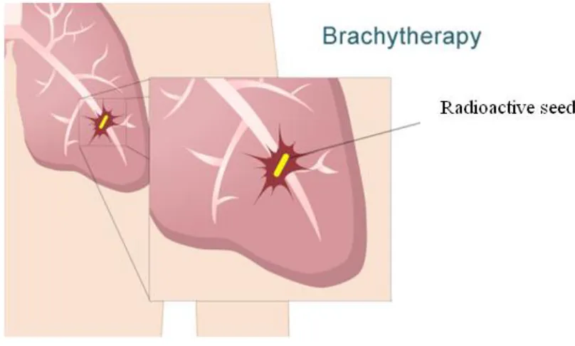
Brachytherapy
Brachytherapy consists of placing radioactive sources near or within the cancerous tumor
so as to destroy it and prevent further spread of the cancer. This radiation therapy is a
short distance concentrated radio therapy (―brachy‖ means ―short‖ in Greek). It can be
used in combination with other treatment methods for better results.
The two main brachytherapy types are Low Dose Rate (LDR) and High Dose
Rate (HDR) brachytherapy. This treatment is widely used to treat prostate cancer [15]–
[17] and recent advances show its viability to lung cancer treatment [6].
Endobronchial brachytherapy [18]–[20] which involve placing a radioactive
source near the tumor through the use of a catheter and guide wires is a type of HDR
brachytherapy [15]. As the name HDR suggests, it consists of a very highly radioactive
source of energy placed at the target location for a fairly small amount of time. Once the
procedure is completed, the source is retracted.
Figure 1.4: Brachytherapy
Interstitial Brachytherapy [17], [21]–[23] which involves direct implantation of
irradiation is a type of LDR brachytherapy [16]. In this case, the time for which the tumor
is subjected to radiation is significant as compared to HDR, but the dose of radiation is
fairly small. The sources are commonly referred to as ―seeds‖ which are the size of rice
grains.
Figure 1.5: Brachytherapy seeds
Usually multiple seeds are placed at different locations in the tumor based on a
dosimetry plan, so as to provide sufficient dosage to destroy the cancer cells. A needle
and a plunger design is used to deploy the seed at the given target location. Various types
of brachytherapy needles based on different gauge sizes are available. Typical needle and
plunger pairs of 2 different gauge sizes are shown below.
The dosimetry plan provides seed locations based on biopsy results and
preoperative screening. The radiation decays to a safe level over a period of time. In [21],
[24], it is shown that brachytherapy can be used in conjunction with wedge resection so
as to address the possibility of recurrence of cancer due to possible remnants of cancer
cells in the operated area of the lung. An important aspect of the treatment is the imaging
feedback. Imaging [25]–[27] helps in determining the locations of tumors and in
establishing target locations. It is also used to scan for the implanted seeds and to
Figure 1.6: Brachytherapy needles and stylets of different gauge size
The advantages of brachytherapy can be summarized as being a local radiation
therapy, a larger and more focused dose can be applied as compared to external beam
therapy. It has a minimized risk of side effects and requires shorter treatment and
recovery times compared with other treatment techniques.
There are some shortcomings to brachytherapy as mentioned in [28], [29] about
the migration of seeds to other parts of body causing possible complications, and in some
cases even causing development of new cancerous tissue. The way to prevent such
undesirable effects currently is to follow-up on a regular basis to make sure that the seeds
have not migrated. A recent research shows promising results to overcome the seed
migration issue of brachytherapy [30]. It enhances the structure of the seed by adding a
bio-absorbent polymer coating which allows the seed to affix itself at the target location.
Another solution to the migration problem is to use seeds in the form of strands that can
Some of the sources of error in this treatment technique are subjected to the errors
caused in imaging (incorrect recognition of tumor, target, seed etc.). Hence, it is
important to have an accurate and effective imaging and visualization solution to make
the overall system robust [31]. Also the problems of needle flexing and tissue
deformation need to be compensated for to comply with the required accuracy [32], [33]
1.4.2.2
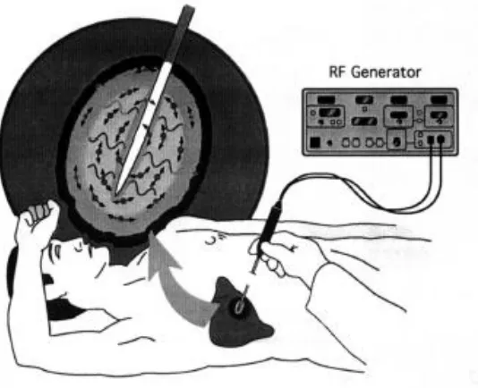
Radiofrequency ablation
This is a minimally invasive thermal ablation technique in which a needle-like electrode
is placed inside a tumor under image guidance. The electrode consists of an insulated
metal shaft except for an exposed conductive tip that is in direct electrical contact with
the cancerous tissue through which radiofrequency waves are passed with frequencies
ranging from 450 to 500 KHz. This induces ionic agitation that destroys the cancer cells.
Figure 1.7: Radiofrequency ablation
The benefits of this technique include its ability to produce large volumes of
coagulation necrosis adding to the advantage it has of a localized way of treating cancer
[9]. Multiple radiofrequency electrodes can be used together to get larger necrosis
volume [34]. The usual setup of radiofrequency ablation consists of single or multiple
as reference electrodes closing the electrical circuit and one or more image guidance
modalities such as US, CT or MRI to help trace the needle towards the target. Figure 1.8
shows the radiofrequency ablation probe used to conduct experiments for this thesis.
Figure 1.8: Radiofrequency ablation probes
It is essential to have image guidance to ensure proper placement of the electrode
tip at target locations and to obtain feedback of the ablation process while the procedure
is ongoing. Imaging is also used to evaluate the treatment after ablation is completed
[35].
1.4.2.3
Microwave ablation
This is a similar concept to radiofrequency ablation except that microwave energy is used
for ablation. Microwave ablation can be considered as a special case of dielectric heating,
the tumor acting as a dielectric material in this case [36]. Microwaves lie in the frequency
range between 900 to 2450 MHz.
When applied to tissue, they induce an alternating electromagnetic field that
forces water molecules to vibrate at a very high frequency. Due to this kinetic energy of
water molecules, heat is generated thus causing thermal ablation. Microwave ablation is a
relatively new technique that can be used in any type of procedure where radiofrequency
ablation is currently used to ablate various forms of tumors. It offers almost all the
benefits that radiofrequency ablation has to offer in addition to some advantages such as
reduced procedure times, reduced heat-sink effects and lower intra-procedural pain and
complication rates [37], [38]. The microwave ablation setup usually consists of a
microwave ablation probe and a microwave energy generator. There is no need of
grounding pads in microwave ablation which can be considered as another advantage
over radiofrequency ablation resulting in a simpler procedural setup. Multiple microwave
ablation probes can be used to achieve a bigger ablation volume. Image guidance helps to
maneuver the needle to the target location.
1.4.3 Current scenario
For most of the tumors whether formed in the liver, breast, kidney, prostate etc., the basic
treatment techniques of resection, chemotherapy, radiation therapy are preferred when the
diagnosed cancer is at an early stage. Cancer recurrence rate is the lowest for these
techniques. Combination of these techniques can be applied to minimize cancer
recurrence [39]. Use of brachytherapy and other localized treatment techniques are
usually performed when the patient is not deemed to be suitable for surgical resection due
to age, health condition, the state of the cancer or other relevant reason. Minimally
invasive surgery proves to be a good alternative as it significantly reduces trauma [40].
At present HDR brachytherapy and radiofrequency ablation techniques are being
used for minimally invasive lung cancer treatment. CT, MRI imaging is used as a
feedback modality to locate the targets and seed locations for cancer treatment due to the
drawback of using US (produce bad images in presence of air). HDR brachytherapy is
preferred over LDR brachytherapy as the issue of seed migration is averted in the former
(since the radioactive sources used are retracted when the procedure is completed).
used effectively as an imaging modality (US imaging is much better in the prostate
compared to the lung).
Among thermal ablation techniques, radiofrequency ablation is more commonly
used since it is relatively older technique with sufficient clinical results demonstrating its
effectiveness [41], [42]. Recent research described in [38] compares radiofrequency
ablation and microwave ablation and shows that microwave ablation gives larger ablated
necrosis region in relatively lower procedural time and can be alternative treatment
option for lung cancer patients. The results are still from early stage research work and
more tests need to be completed before microwave ablation can be completely accepted
as a lung cancer treatment option. However, it has been proved that microwave ablation
has all the benefits that radiofrequency ablation provides [43] while not being affected by
the ―heat sink‖ drawback for radiofrequency ablation [38].
For minimally invasive surgical techniques to work well, imaging is very
important as it provides ―real-time‖ feedback of the surgical site and helps to evaluate the
entirety of the procedure [44]. Knowing the locations of the targets where brachytherapy
seeds need to be injected, or the locations where the ablation probe antenna needs to be
placed is vital. At certain times, situation arises where the needle gets deflected while it is
being inserted in the tissue. It becomes critical to assess the situation, align and
re-adjust the needle so that the tip can reach the specified target. Currently, the most feasible
resource for imaging is US, which is cheap to use and gives live feedback of the surgical
site, however, it is not possible to understand the complete scanned region by visualizing
just a 2D image plane. US work well with liver and prostate brachytherapy. But with
lungs due to the air artifacts present within the tissue, the image quality is much worse
and makes it hard to understand the surgical site (drawback of US). With added motion
due to heart beats and respiratory system, reaching the target becomes even more
complex for the user.
A need to address the above-mentioned drawbacks provided the motivation for
the work described in this thesis. A system would be designed that would overcome the
would enable a clinician to perform cancer treatment more intuitively with a better
cognition of the surgical site. The following sections describe the image-guided
intervention approach and use of robots in the surgical field followed by a description of
an older version of the system that was implemented at CSTAR (Canadian Surgical
Technologies & Advanced Robotics, London ON, Canada). The final section lists the
contributions made by this thesis and implementation of the InterNAV3D application
system.
1.5
Image-guided intervention
Image-guided intervention is a relatively novel treatment approach which refers to the use
of computerized imaging systems to provide feedback while treatment is being
performed. The common medical imaging modalities include US, CT, MRI. With the
help of this feedback, surgical tools are inserted into the body of the patient and
maneuvered to the desired target location. Computers can also be used to process the
images thus captured so as to segment out the physical attributes present in them. This
helps in improved diagnostic capabilities, improved target selection and localization
during the procedure. Integrating a virtual reality environment that depicts the surgical
site and the movements of the tools and organs, could assist the user to gain better
cognition for carrying out the treatment procedure. An image-guidance interventional
system typically integrates image acquisition, image processing (registration,
segmentation, etc.), virtual reality visualization and planning scheme techniques.
Exploiting these, accurate interventions with minimal errors could be delivered.
Image-guided intervention techniques are used in numerous types of surgical procedure [45]–
[49]. Figure 1.10 shows a typical image-guided intervention platform. The advances in
technology help to achieve improved patient outcome and safety, overall reduction in
Figure 1.10: Image guided intervention platform
1.6
Robot-assisted minimally invasive surgery
Surgical robotics is a technology-driven area of medicine which has experienced a
tremendous growth and improvement over the last 2 decades to improve upon the current
scenario of surgical applications, mostly in MIS. It is driven by the motivation to achieve
greater precision, less procedural time and faster recovery of patients (as a result of
minimizing invasiveness) by overcoming the limitation of MIS so as to enhance the
capabilities of the surgeon. Various research projects described in [2], [50]–[52] show the
applications of robotics in MIS.
The primary drawback of hand-held tools for MIS is the limited dexterity offered
by the surgical tools. These tools are not generally ergonomic and are in general
challenging to learn to use efficiently. The surgeon has to hold tools the entire time and
needs to be extra cautious not to make any aberrant movements. Additionally, hand
tremors cause unwanted motions at the tool tip which can lead to inaccuracies and errors
during surgery. Inclusion of a robot between the surgeon and the patient could help
to remove any sudden jerks or motion. The use of a master-slave robot combination
(tele-operation) serves to improve the efficiency of the surgeon by providing more ergonomic
conditions for the surgeon who sits at the master console during surgery. The most
important aspect of robotic surgery is the improved accuracy of tool motion and
placement. The new technique to include specialized tools with multiple degrees of
freedom further enhances the surgeon’s ability to perform complex procedures with ease
[54]–[56]. The use of robots also reduces the time required to complete a surgical
procedure [53], [57] compared to conventional MIS. Various operational modes such as
auto aligning the tool, auto tool insertion etc. can be performed by the robot using the
interface design provided. Several papers have been published in recent years that
summarize the current state of surgical robotics [58], [59].
1.7
InterNAV
Due to high mortality of lung cancer, new projects are being implemented to
improve its treatment system. Robotic technologies are being applied to make the system
more robust, automated and easy to use. They reduce the errors generated due to hand
tremors and fatigue [60], [61]. Integration of robotic technologies also provides the
needed dexterity for certain surgical tasks. Image processing techniques improves the
quality of the images and assists the user to perceive the artifacts present in the images
clearly. The addition of a virtual reality environment provides an enhanced perspective of
the surgical site. One such research project has been implemented at CSTAR and is a
novel approach for interstitial brachytherapy. The system consists of master-slave
operation, a seed placement device for injecting radioactive seeds and a laparoscopic
ultrasound (US) probe for real-time imaging. These instruments are mounted on surgical
robots (a ZEUS and an AESOP) made by Computer Motion Inc. These robots have been
modified to bypass their controllers to obtain open architecture systems. This allows the
implementation of custom designed controllers. Electromagnetic trackers were placed on
the tools in order to track their real-time orientation and position [2]. Figure 1.11 shows
Figure 1.11: InterNAV setup for lung brachytherapy
As part of the system, a visualization and control software known as InterNAV
was developed. It consists of a Graphical User Interface (GUI) which interacts with the
robotic brachytherapy setup and the US machine, giving the ability to control the entire
system. It is a virtual reality environment that displays a set of 2D US images in a 3D
world. It enables the user to select target locations for brachytherapy seed injection.
An automated seed injection device mounted on a robotic arm is used to navigate
and drop the seeds at those targets. A first person eye view of the system looking from
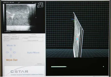
the needle tip was implemented which helps in easy guidance of the needle. Figure 1.12
shows a snapshot of the InterNAV interface. Researchers have shown that the use of a
robotic system and image guidance reduces tissue trauma and improves seed placement
accuracy [4].
Though the system provides good results as compared to an open surgical
procedure [2], [62] there are some drawbacks:
The system provides a 3D virtual world view with a 2D image plane suspended in
it at the specific location with respect to the electromagnetic tracker co-ordinate
frame. Though it helped to visualize and understand the surgical site, it was very
difficult to gain perspective of the size and structure of the tumor. Even with
pre-operative imaging, judging the orientation of the tumor was very non-intuitive.
The system lacked the capability to capture and visualize 3D images.
At certain times, the needle bends and deflects while being inserted into tissue.
The system lacked the features needed to provide information about the structure
of the needle and its probable location after needle bending.
Knowing the path history of the needle tip is very helpful in order to visualize the
probable path the needle might take. This would help the clinician to retract the
needle along the same path so as to keep tissue damage to a minimum. The
system had no feature implemented for needle retraction.
The use of US in the lung makes it prone for faulty recognition. Applying image
processing techniques enhance the images and guide the user to determine various
physical artifacts present in an image. InterNAV provided a real-time imaging
feedback but lacked the feature to enhance the images for improved visualization.
For lung cancer treatment, there is always a residual motion even after a lung is
contralateral lung. The previous system had no features to account for motion
compensation or visualization in the virtual world.
InterNAV lacked the feature to implement other novel lung cancer treatment
techniques such as radiofrequency ablation and microwave ablation.
A feature to use the system as an offline processing and training tool by using
pre-captured image data was not available in InterNAV.
Re-evaluation and re-optimizing the dosimetry plan in real time is necessary as
erroneous seed deployment may occur often. The process to re-evaluate the
locations of the seeds and accordingly update the visualization system was also a
missing feature.
All of the above drawbacks of InterNAV led to the development of a much more
extensive, accurate and integrated system that has been termed InterNAV3D in this
thesis.
1.8
Thesis contribution
This thesis mainly focuses on the development of InterNAV3D. It is a complete new
system that was developed to incorporate all the missing features mentioned above and to
overcome the drawbacks of the previous version of InterNAV. The various enhancements
mentioned below are integrated in the new system which comprises the major part of the
research contribution of this thesis.
A complete new and enhanced system, InterNAV3D, has been developed and
evaluated. It uses the Visualization Tool Kit (VTK) and the Insight segmentation and
registration Tool Kit (ITK) as the major developer interfaces for the design of the system.
A new experimental test-bed has been developed along with the software interface which
implements image processing techniques.
The new system includes a feature to grab a sequence of images in certain
add multiple image volumes have been implemented which helps to form a complete 3D
structure of the surgical site. It not only overcomes the problem of target selection in 2D
view but also helps in optimizing dosimetry planning. Various modules such as surface
reconstruction, cross-sectional slicer, etc. are included in the new system. These modules
help to visualize the tumor in a more intuitive way. The surgical tools are modeled as
Stereo Lithography (STL) objects and rendered in a real-time 3D visualization world,
providing a more realistic view of the surgical site. Needle path projection, prediction and
visualization history of needle tip location are integrated. It provides more generic
real-time view of the needle structure and helps to understand the needle movement and its
tracking behavior. An algorithm to visualize the needle tip and compensate the
visualization for needle bending is integrated. Image processing techniques such as
opacity control and visibility control to explore properties of the physical entities present
in the 3D view have been implemented. Algorithms performing region growing
segmentation, needle tip detection, etc. have been implemented. The full dexterity of
robotic movements is utilized for capturing US images in various modes such as round
(rotational) sweep, straight (flat) sweep, and ablation sweep.
An algorithm to construct 3D volumes using a series of captured images has been
implemented. Various ex-vivo experiments were performed and the results are described
in this thesis. Radiofrequency ablation and microwave ablation, along with a C-arm
X-ray imaging modality have been incorporated in the newly designed system to improve
the performance and reliability of tumor visualization and the lung cancer treatment
procedure. A novel approach to estimate the entirety of the thermal ablation by evaluating
the changes in the 3D volume is discussed. Recording and evaluating the target
locations, compensating for any motion during visualization has been implemented.
Ex-vivo and in-Ex-vivo experiments to evaluate the system were performed and the results are
described. The versatility of the new system allows the implementation of the developed
techniques for similar cancer treatment procedures in other organs such as liver, kidney
1.9
Thesis outline
Chapter 1 – Introduction: This chapter describes the current scenario for lung cancer
treatment and gives a literature review followed by the motivation and research
objectives of the thesis.
Chapter 2 – System Architecture: This chapter focuses on the hardware and software
components of the system and also outlines the various algorithms developed and used in
the system. It details the working of the system with an added focus on the integration of
all the components
Chapter 3 –User Interface: This chapter presents an overview of the GUI, various
modules developed and different modes of operation.
Chapter 4 –Experimentation and Results: This chapter gives a detailed overview of the
various experiments performed and the results obtained. It also outlines several sources
of errors, the calibrations performed and the logic behind the experiments conducted.
Chapter 5 –Conclusion and Future work: This chapter summarizes the overall design of
the InterNAV3D system, its potential applications for cancer treatment in other areas, and
Chapter 2
2
System Architecture: Hardware and Software
As discussed in the previous chapter, there is a need to develop novel technologies to
help treat cancerous tumors in the lung. InterNAV [3] was conceived as a research and
development project to integrate the MIS technique of brachytherapy and robotics with
virtual reality environment.
The contribution of this thesis was the development of InterNAV3D, which was
created as an enhancement of InterNAV. It incorporates techniques of image processing,
3D visualization, motion simulation, and implements novel software modules for better
needle maneuvering. Integration of all new techniques makes it a state-of-the-art package
which improves on the time, speed, accuracy for the complete procedure with enhanced
feature recognition techniques. The details of the implemented algorithms, new features
and modifications will be provided in subsequent chapters. This chapter deals with the
system architecture. Being a mechatronic system, it would be easy to understand its
working by dividing the system into its hardware and software components and working
down to the core developments.
Figure 2.1 illustrates the system and its organization. The following section
details all of the individual components and their contribution to system co-ordination.
2.1 System overview
InterNAV3D has a software interface front end package installed on a computer which
acts as a remote workstation. It is a graphical user interface that has a virtual reality 3D
environment. It renders the physical entities present within the surgical site and mimics
their motion in the virtual world. The 3D environment represents the Cartesian
co-ordinate space of NDI’s Aurora electromagnetic tracking system [63]. The field generator
is placed below the test-bed such that the generated alternating magnetic field covers the
surgical site. The virtual environment can visualize any 3D objects, volumes and similar
help process the images received from the imaging modality. Currently, US is used as the
primary real-time imaging feedback. The US machine used for this project is the
Sonixtouch from Ultrasonix [64] and the US probe used is the laparoscopic probe
LAP9-4/38. The output of the US machine is directed to a frame grabber, the Matrox Vio-Duo
by Matrox imaging [65] which is installed on the PCI express slot of the computer
motherboard. MIL is the software library that takes care of getting the US images from
the frame grabber. The electromagnetic trackers attached to the needle tool and US probe
feedbacks the current position and orientation information needed for virtual rendering.
Figure 2.1: System overview and working
The field generator is installed under the physical setup/test-bed as shown in
Figure2.1. The feedback from Aurora is given to the computer. The InterNAV3D
tracking information from Aurora. VTK is a visualization library that was integrated with
InterNAV3D for 3D mapping of the given information. It runs within InterNAV3D and
gives visual representation of all the data. It takes care of all the mapping of the physical
components in the virtual reality world. The inbuilt modules created in InterNAV3D run
on VTK for visualization and rely on ITK for image processing. VTK and ITK go hand
in hand in getting all the data to be processed and visualized as the system demands.
The needle tool and the US probe are mounted on the ZEUS and AESOP (Automated
Endoscopic System for Optimal Positioning) robots which are attached to the computer
through a controller device. The feedback from the magnetic tracker and the US machine
helps in moving and orienting the robots so as to maneuver the needle tool and the US
probe to be placed at the required location within the surgical site. There are two modes
to maneuver the needle to the target: auto-mode and manual-mode. The auto mode inserts
the needle automatically so that the needle tip hits the target whereas the manual mode
lets the user control the needle maneuvering.
2.2
System initialization and working
The working of the system can be explained by studying the flowchart provided in Figure
2.2. We need to initialize the hardware and software components before the 3D
environment is generated.
At system initialization, SAW (Surgical Assistant Workstation) commences its
communication pipeline. It opens connections to hardware profiles (AESOP and ZEUS
robots, Aurora magnetic tracker and electromagnetic sensors, Matrox frame grabber) so
that they are ready to be used. Software libraries such as VTK and ITK are initialized.
The user needs to choose one of the sweep profiles (straight-flat sweep,
round-rotation sweep, palpation sweep or ablation sweep) and provide the required parameters
such as the number of images that need to be grabbed and the divergence (angle or time)
between successive images. Accordingly, appropriate commands are passed to the US
robotic arm which moves in the required fashion. The software then grabs images during
the sweep motion. At the same time, the values from the electromagnetic tracker are
recorded. Algorithm to convert the set of 2D images to a 3D image volume conforming to
the shape of the sweep capture mode is initiated. As the 3D image is generated, it needs
to be rendered at appropriate location in the virtual 3D space. For this, the
electromagnetic sensor values recorded earlier are used and after applying appropriate
calibration values from sensor to the US image location (discussed in Chapter 4); the
volume is rendered in 3D space. Appropriate visualization parameters such as the opacity
function and color-transfer function are applied. Simultaneously, surface reconstruction
and region growing algorithms for locating the tumor are performed. The results are
rendered on the 3D visualization window. If the user is satisfied, he/she can go to next
step, else he/she can use the various built-in modules such as window thresholding,
piece-wise opacity transfer function and many other to make the data more clearly
presentable for understanding the nature of the surgical site, location of tumor, its
structure and size. After this step, the user needs to select the target where he/she wants
the needle tip to go. Once selected, the user can proceed manually or use the auto-move
method built in the software to align and maneuver the needle to the selected target.
There is another electromagnetic sensor present on the needle which helps to visualize
the needle in the 3D visualization window. The tracker information is constantly queried
and the visualization window is updated accordingly. It provides real-time feedback of
the location and orientation of the tools connected to the robot and helps in determining
appropriate commands that need to be sent to the robot to move it in a particular
direction. The needle needs to be calibrated beforehand using the pivot calibration
method (discussed in Chapter 4). The user can grab multiple volumes at several distinct
locations during the procedure. These volumes are rendered and stitched together to form
an enlarged 3D structure of the underlying tissue and provides better understanding of the
co-relating with the adjacent physical entities and other similar structures. The overall
visualization of the surgical site is enhanced and helps user to understand the virtual
world. It improves the visual perception of the user and helps him/her decide the next
course of action.
Certain times needle gets deflected from its intended path within the tissue during
an insertion procedure. It happens due to uneven tissue stiffness, the design of needle tip
(such as bevel tip) or any similar reason. Grabbing multiple volumes during a needle
insertion procedure provides with the useful information of the needle behavior within
the tissue. It guides in determining the needle shape and location. Real-time US video
feedback with enhanced image processing algorithms and visualization modules help to
pin-point the location of the needle tip. Options for needle path prediction, needle path
projection, etc. assist the user to predict and visualize the future path that the needle
might take and in turn allow to update the needle orientation. The user determines the
error with respect to the intended path and updates the needle maneuvering accordingly.
The required course of action is revised and the needle is kept on the required track to the
target. Once the user thinks he/she has reached the target, he/she performs a re-evaluation
of the surgical site and applies the imaging and visualization modules needed to ensure
that the target was reached successfully and accurately. Once the user is satisfied,
appropriate treatment techniques such as deploying brachytherapy seed and/or thermally
ablating the tumor are performed. If the user is not satisfied, he/she realigns the needle
and repeats the complete maneuvering steps. After the method is performed, the needle is
retracted using the same path as for insertion (using the needle path history visualization),
to ensure that tissue damage is kept to a minimum and that the needle is retracted safely.
Once the needle is out of the specified area, the user moves to the next target/tumor and
performs the same steps or else stops the system if the procedure is deemed to be
completed. This is essentially how the InterNAV3D system is expected to be used. More
2.3
System components
The system hardware and software components are described in detail below. Specific
attention is given to the hardware that was used and the software that was integrated in
the InterNAV3D system and the functions that they perform.
2.3.1 Hardware components
The following are the major hardware components.
2.3.1.1
US machine and imaging
As discussed in the previous chapter, US remains the most feasible source of real-time
imaging due to the ease of use, cost-effectiveness and benefits over other imaging
techniques (US being a non-ionizing radiation) [4].
The US machine ―Sonixtouch‖, shown in Figure 2.3, from Ultrasonix was used
for the experiments described in this thesis. The Sonixtouch machine is a diagnostic US
system which comes with an US Research Interface (URI) installed. The URI is a term
referring to the US machines which allows for various diverse operational modes that
purely clinical system does not have. It gives a wider range of parameter modifications
for generating US images. In addition to the URI, the US machine used also allows
transducer prototyping and development of commercial US applications. It has an
elastography mode that can be helpful for better image analysis (to be integrated in later
versions of InterNAV3D). It is of significance to mention here that InterNAV3D is very
customizable to accommodate any other US imaging system as well as any other medical
imaging technology such as CT, MRI etc. A comprehensive outline of the principles
behind the technology can be found in the literature, e.g., [66]–[72]. The US probe used
for InterNAV3D is a flexible laparoscopic probe LAP9-4/38 as shown in Figure 2.4.
Figure 2.4: Laparoscopic probe used
The characteristic of this probe is its ability to move in 2 different degrees of
Figure 2.5: US probe bent from the flexible part
There are switches provided at the probe handle that help to maneuver the probe
transducer. Currently this feature is not used in InterNAV3D since the robot used for the
probe movement provides a higher dexterity and has better controlled movement and
placement. For the experiments performed, the flexibility of the transducer end was
restricted by attaching an external sleeve (manufactured in 3D printer) as shown in Figure
2.6.
2.3.1.2
Electromagnetic tracker
InterNAV3D is designed for use in minimally invasive interventions. One way to track
the tools during surgery when they are inside the patient’s body is to use optical tracking
(placing physical markers on the tools and using computer vision to deduce its position
and orientation) by getting the video stream output from the endoscope. Though it is
possible to get position and orientation in space using imaging techniques, it is difficult to
determine these when the vision is blocked (for optical tracking to work, it is favorable to
have a clear line of sight to the markers). For such cases, electromagnetic tracking can be
helpful. The sensors can be installed on most of the surgical tools such as catheters,
bronchoscopes, needles etc. [63], [73]–[77]. This tracking system determines the spatial
parameters of embedded sensor coils when placed in an electromagnetic field. The
concept behind the technology can be explained by looking at Figure 2.7.
Figure 2.7: Working of electromagnetic tracking system
A varying magnetic field is generated using the field generator device. When the
sensor coil is placed inside this magnetic field, voltages are induced in them. Using these
induced voltages, a measurement system determines the position and orientation of the
Figure 2.8: Aurora field generator
The magnetic field generated is of low field strength and can pass safely in human
tissue, thus allowing the required measurements even when the line of sight constraint is
not satisfied. For InterNAV3D, NDI’s Aurora system was used as shown in Figure 2.9.
This system is designed to be functional in environments with medical grade
metals. Aurora comes with the Aurora Application Program Interface (API) which can be
customized and used for research and development applications. This system is compliant
with the medical equipment safety standards. A drawback however is still present. The
measurement accuracy of the system is reduced if any ferromagnetic material comes in
the vicinity of the magnetic field [80], [81]. Hence, proper placement of the field
generator and use of compatible tools is advised, so as to minimize any such interference
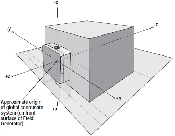
distortion. The origin of the co-ordinate system of Aurora lies at the center of the front
surface of the field generator as shown in Figure 2.10.
Figure 2.10: Field generator and the Cartesian co-ordinate space
Aurora supports two types of sensors based on the Degrees Of Freedom (DOF)
needed for tracking: 5-DOF and 6-DOF.
They are manufactured in custom shapes (different lengths and radii) which make
them more accessible for varied application requirements. A typical 5-DOF and 6-DOF
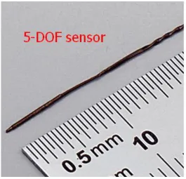
Figure 2.11: 5-DOF sensor
The diameter of the 5-DOF sensor is 0.5 mm and its length is 8 mm; whereas for
the 6-DOF sensor the diameter is 1.8 mm and its length is 9 mm. Depending on the
application and the physical position where the sensor needs to be installed, other sensors
with different diameters and lengths can be used. The sensors are good for use in in-vivo
applications.
The following table shows the accuracy of the tracking system as per NDI
website.
Table 2.1: 5-DOF sensor accuracy
5-DOF sensor RMS (Root Mean Square) 95% confidence interval
Position 0.7 mm 1.4 mm
Orientation 0.2 degrees 0.35 degrees
Table 2.2: 6-DOF sensor accuracy
6-DOF sensor RMS (Root Mean Square) 95% confidence interval
Position 0.48 mm 0.88 mm
Orientation 0.3 degrees 0.48 degrees
The 5-DOF sensor gives the location of the sensor coil in Cartesian co-ordinate
space (x, y, and z) with pitch and yaw as the orientation parameters. It lacks the ability to
determine roll which is possible in 6-DOF sensor. Pitch, roll and yaw are the rotation
angles made by the object around the 3 orthogonal axes passing through its origin. Figure
Figure 2.13: Roll, pitch and yaw
Depending on the tool, an appropriate sensor was selected. For experiments with a
brachytherapy needle, the sensor can be aligned to the axis of the needle which makes the
roll information vestigial. Hence a 5-DOF sensor was used. The sensor was placed
aligned to the axis of the needle as shown in Figure 2.14.
Figure 2.14: Bevel-tip needle with 5-DOF sensor enclosed
For thermal ablation needles, 6-DOF sensors were used since the information of
roll was necessary to determine the location of the needle tip (by using the pivot
calibration method). Specialized sleeves were manufactured for placing the sensor on the
ablation needle and for attaching it to the robot. Figure 2.15 shows one such sleeve
Figure 2.15: Sleeve for radiofrequency ablation probe with the channel for EM
tracking sensor
Figures 2.16 and 2.17 shows the ablation tools with the sleeve placed over them
and the sensor attached within the sleeve.
Figure 2.16: radiofrequency ablation probe with sensor attached to sleeve