Adaptive anti-saturation fault-tolerant control for integrated
missile guidance and control
Peng Li1, Qi Liu1, Chen-Yu He and Xiao-qing Liu2*
1.The School of Information and Engineering at Xiangtan University,Hunan Changshan ,411100,China 2. Department of Precision Instruments, Tsinghua Universit javascript, 100084, Beijing, China
Abstract: This paper studies the integrated design problems of control and guidance with parameter uncertainties, target disturbances, input constraints and actuator faults. Firstly, based on the integrated
design idea of the missile guidance and control, the auxiliary variable is used to establish and transform
it into a cascade system with input constraints, actuator faults and disturbances of unknown upper
bounds. Secondly, the adaptive anti-saturation dynamic surface fault-tolerant controller is designed by
using the back-stepping method, adaptive control, auxiliary system and tracking differentiator. By
introducing the tracking differentiator and tangent barrier Lyapunov function, the computational
explosion problem in the traditional back-stepping method is avoided and the angle of attack can be
guaranteed in prospective range, respectively. Finally, the theoretical proof of the designed control
strategy is given to ensure that the states of the closed-loop system are bounded. At the same time, the
digital simulation of the maneuvering target of different maneuvering forms is carried out, which
further illustrate the effectiveness and robustness of the designed control schemes.
Keywords: Missile guidance and control; Dynamic surface control; state constraints; Input saturation; Actuator faults
1. Introduction
The design of the missile guidance and control system is the key factor for the missile flight success
and accurate strike [1]. In the tradi1tional missile design method, the interaction between the guidance
system and the control system is often neglected. When it is flying at big angles of attack and aimed at
intercepting large maneuvering targets, the coupling relationship between the guidance and control
systems may cause the degradation of the system performance, and even the failure of intercepting
missions [2]. Therefore, the design method of integrated guidance and control has attracted the
Associate ProfessorXiangtan University, email: [email protected].
Ph.D. Student, Xiangtan University, email: [email protected]. Ph.D. Student, Xiangtan University, email: [email protected]. Ph.D. Student, Tsinghua Universit, email: [email protected].
attention of many scholars.
In recent years, the nonlinear control theory has been widely used in the integrated guidance and
control of flight control systems[3-6]. In [6], the adaptive dynamic surface sliding mode control law
was designed based on the integrated guidance and control model of missile pitch channel to improve
the missile guidance precision. In [7-8], the integrated guidance and control law was designed by using
the sliding mode control and back-stepping control. In [9], the integrated model of guidance and
control was transformed into the block diagonal model of attitude and velocity subsystem. Based on the
sliding mode control theory and fuzzy control theory, the analytical solution of block diagonal
combination was obtained. In [10-11], for the integrated model of missile guidance and system, the
integrated controller of guidance and control was designed through the adaptive control technology and
neural network theory. Integrated missile guidance and control with state constraints in practical
systems[12]. In [13], in order to avoid the influence large angle of attack, flight strategy with
angle-limited was designed. In [14-15], the back-stepping control with states constraints was designed
for nonlinear systems constrained by using barrier Lyapunov function. In [16], the adaptive
back-stepping controllers with state constraints was proposed for hypersonic vehicle. In [17], an
adaptive dynamic surface controller was proposed for systems with state constraints by using the
differentiator and barrier Lyapunov function.
In the actual design process of control system, the input saturation problem must be considered
[18-20], If the input constraint is not considered in the controller design, the actuator may be saturated
during the actual execution of the control law, which may lead to the degradation of the guidance
performance or even the instability of the guidance system. In [21-22], an anti-saturation adaptive
back-stepping controller was designed by introducing an instruction constraint system. In [23-24], the
guidance law was designed through the adaptive technology and auxiliary systems, which can solve the
input saturation problem. In addition, due to the external disturbances, model parameter uncertainties
and input saturation of the missile guidance and control system, which can more likely to lead to
actuator fault. In [25], the dynamic surface fault-tolerant controller was proposed by using the extended
state observer and dynamic surface control method. In [26],an adaptive back-stepping sliding mod
fault-tolerant controller was proposed for integrated guidance and control system. In [27], an adaptive
fault-tolerant controller was provided for the integrated guidance and control system with state
the problem of integrated missile guidance and control, this paper aims at the integrated control model
of the missile pitch plane and maneuver target with unknown upper bound. Based on the dynamic
surface control, adaptive control technology, auxiliary system and tangent barrier Lyapunov function,
the adaptive anti-saturation fault-tolerant controller is designed, which can make the angle of attack
satisfying in prospective ranges. Compared with the existing works, the main contributions of the thesis
are shown as follows:
(1) A novel tracking differentiator filter is developed in conjunction with the back-stepping control
that eliminates the complexity problem.
(2) The tangent barrier Lyapunov function is introduced in the adaptive fault-tolerant control strategy
to guarantee the angle of attack keep within the certain ranges.
(3) Input saturation, actuator faults and state constraints are taken into account to design controller,
which makes the designed controllers have practical significance.
The structure of the rest of the thesis is organized in following manner. Section 2 presents an
integrated guidance and control system model. Section 3, an adaptive anti-saturation dynamic surface
fault-tolerant controller is proposed. Section 4 gives numerical simulations of the proposed controllers.
In Section 5, the conclusion of the thesis is presented.
2. Problem statements
The two-dimensional plane intercept geometry of the missile-target is shown in Fig.1, The M and T
represent the missile and target respectively. The dynamic equation of the relative motion of the
missile-target can be obtained [6].
m
V
t
V
t
q
q
m
M
r
T
Fig.1. Two-dimensional engagement geometry
cos( ) cos( )
t t m m
r=V q−
−V q−
(1)sin( ) sin( )
t t m m
rq= −V q−
+V q−
(2)/ t a Vt t
= (3)/ m am Vm
= (4)velocity and line-of-sight angular rate. VM,
mandam represent velocity, flight path angle and lateralaccelerations of the missile, respectively. Vt,
t and at denote velocity, flight path angle and lateralaccelerations of the target respectively.
Computing the first order derivative of (2), yields
[ cos( ) cos( )]
cos( ) cos( )
t t m m
t t t m m m
rq rq q V q V q
V q V q
+ = − − − − +
− − − (5)
Let Vq=rq,at=Vt
t,am=VM
m, using (1)-(4) can be derivedcos( ) cos( )
q q t t m m
r
V V a q a q
r
= − + − − − (6)
Refer to [11], the differential equations of pitch motion can be described as
cos
M
M M
d
mV Y mg
dt
= − (7)
z
z z
dw
J M
dt = (8)
cos
M M
dx V
dt = (9)
z
dv w
dt = (10)
M
v
= −
(11)From (7), we can have
(
)
1
cos
M M M M
a V Y mg
m
= = − (12)
Substituting (12) into (6) yields:
(
)
1(
) (
)
cos cos cos
q q T T M M
r
V V a q Y mg q
r m
= − + − − − − (13)
Based on (10) and (11) can be rearranged as
(
)
1
cos
z M
M
w Y mg
mV
= − − (14)
According to (8), we get
z z
z
dw M
dt = J (15)
The lift force and pitching moment of the missile are defined as
(
)
57.3 z
y y z
Y = qs c+c (16)
2
57.3 57.3
z
z
w z
z z z z z
M
qsl m
M w qslm qslm
V
= + + (17)
Substituting (16)-(17) into (13)-(15) and applying cos
(
q−
M)
1, The following integratedguidance and control model can be derived
(
)
57.3
cos cos
a y
q q m m Vq
qsc r
V V g q d
r m
57.3 ay cos m z
M M
qsc g
w d
mV V
= − + + + (19)
2
57.3 a wz 57.3 z
z z z
z z z wz
z z M z
qslm qsl m qslm
w w d
J J V J
= − + + + (20)
where dVq,danddwz are the bounded terms produced by parameter uncertainties, aerodynamic
uncertainties and external disturbances.
Let
11 12 22
2 2
32 33
57.3 57.3
, ,
57.3 57.3
, ,
z z
y y
M w
z z z
z z z
qsc qsc
r
r m mV
qsm qsl m qsl m
b
J J m J
= − = − = −
= = =
(21)
According to (21), then (18)-(20)can be rewritten as:
(
)
11 12 cos cos
q q m m Vq
V =
V +
+g
q−
+d (22)22
cos m z
M
g
w d
V
= + + + (23)
32 33
z z z wz
w =
+ w +b
+d (24)Further, then(22)-(24) can be derived as
( )
( )
1 1 1 2 1 2
x = f x + + x x (25)
( )
( )
2 2 2 3 2 2
x = f x + + x x (26)
( )
(
)
3 3 3 3 2, 3,
x = f x +bu+ x x u (27)
where x1=Vq/
12 , x2=
, x3=wz , u=
z , 1( )
x2 =dVq/
12 , =2 d , =3 dwz ,( )
(
)
1 1 11 1 cos mcos m
f x =
x +g
q−
, 2( )
2 22 2 cos mM
g
f x x
V
= + ,f3
( )
x3 =
32x2+
33 3x .In this paper, the following actuator-fault model and input saturation of missile are considered
( )
sat
u=
v +u (28)where v is the fin deflection command to be determined, 0
1 denotes the actuationeffectiveness, uis the additive fault.
Considering (28) the integrated guidance and control model can be rewritten as
( )
( )
1 1 1 2 1 1
x =f x + + x x (29)
( )
(
)
2 2 2 3 2 1, 2
x = f x + + x x x (30)
( )
(
( )
)
(
)
3 3 3 sat 3 1, 2, 3,
x = f x +b v +u + x x x u (31)
( )
(
)
(
)
1 x1 M1, 2 x x1, 2 M2, 3 x x x u1, 2, 3, M3
(32)
whereM1, M2 andM3 are unknown positive constants.
Lemma 1: For n+1 order tracking differentiator(33), if the input signal
r contains a bounded noise
1− r
, there exist positive constant
i, ri that make inequality (34) hold:(
)
(
)
(
)
1
1 1 1 1 2
1 2
1 1 1
1 2
1 1 1
1 1
sign ...
sign ... sign
sign( )
n n
r r
n i n i
i i i i i i i
n n n n n n n
n n n n
r
r
r
r
+
+ − + −
− − +
− − +
+ +
= − − − +
= − − − +
= − − − +
= − −
(33)
( )
2 1
1 1 1
, 1, 2,..., , 1, 2,..., 1 n i
n i ri i
n j n
j r j j
i n
r j n
+ − +
+ − + +
− =
− = −
(34)
where ri(i=1, 2,...,n+1) is positive constant,
r j(+1) represents jorder differential of
r.3. Controller Design
The adaptive anti-saturation dynamic surface fault-tolerant controller is design for the integrated
guidance model based on the back-stepping method, tracking differentiators, adaptive control, auxiliary
system and tangent barrier Lyapunov function, which can guarantee the angle of attack meets the actual
constraint requirements.
Step1: Define the error variable z1 as follows:
1 1 1c
z = −x x (35)
where x1c is reference signal.
Computing the derivative of (35), it can be obtained that
( )
( )
1 1 1c 1 1 2 1 2 1c
z = −x x =f x + + x x −x (36)
According to (36), the virtual controlx2is designed as follows
( )
1( )
( )
2 1 1 1 1 2sig 1 ˆ1sign 1 1c
x = −f x −k z −k z +M z +x (37)
(
)
1 1 1 1 1
ˆ ˆ
M =p z −l M (38)
where k1,k2,p1andl1 are positive constants,0
1 1. Choose the Lyapunov function as2 2
1 1 1
1
1 1
2 2
V z M
p
whereM1=M1−Mˆ1 is the estimation error of adaptive parameter
Applying (37) and(38), the time derivative of the (39) can be written as
( )
( )
(
)
( )
(
( )
( )
)
( )
(
( )
)
( )
(
)
( )
1
1
1
1
1 1 1 1 2 2 1 2 1 1 1
1
2
1 1 2 1 1 1 2 1 1 2 1 1 1 1
1
2
1 1 2 1 1 1 2 1 1 1 1 1 1
1
2
1 1 2 1 1 1 2 1 1 1 1 1 1
2
1 1 2 1 1
1 ˆ
1
ˆ ˆ
sig sign
1
ˆ ˆ
sig sign
ˆ sig
sig
c
V z f x z x x x M M
p
k z k z z z z z x M z M M
p
k z k z z z z z M M z M M
p
k z k z z z z z M M z l M
k z k z z
= + + + − −
= − − + + − −
− − + + − −
− − + + − −
− −
( )
1
1 2 1 1 1
2 2 2
1 1 2 1 1 1 1 1 2 1 1
ˆ
1 1
sig
2 2
z z l M M
k z k z z l M z z l M
+ +
− − − + +
(40)
To avoid the derivative of virtual controllerx2, the tracking differentiator (41) is introduced as
(
)
1 2
2,1 1 2,1 2 2,1 2 2,2
2,2 2 2,2 2,1
sign
sign( )
r x x
r
= − − − +
= − −
(41)
where r1 and r2 are positive constants.
Apply Lemma1, inequality (42) can be obtained:
2,1 x2 l2,1
− = , 2,1−x2 =l2,2 (42)
where l2,1 and l2,2 are positive constants.
Step2: Define the error variable z2 as follows:
2 2 2
z =x −x (43)
The derivative of (43) can be written as
( )
( )
2 2 2 2 2 3 2 2 2
z =x −x = f x + + x x −x (44)
To guarantee the angle of attack satisfying z2 A with A0 being positive constants, respect to (44), the virtual controlx3is designed as follows
( )
( )
( )
(
)
2 2
2
2 2
3 3 2 2 2 2
2
30 2 2 1 2 2,1 2,2
sin cos
2 2
1 ˆ sign ˆ
sign
z z
A
x k f x
z A A
k z z z M l
= − −
− − + + −
(45)
(
)
(
)
2 2 2 2 2
2,2 3 2 3 2,2
ˆ ˆ
ˆ ˆ
M p z l M
l p z l l
= −
= − (46)
where k3,k30 k4 p2, p3,l2andl3 are positive constants,k3k30,
2
30 A k
A
= +
,
is positiveconstant,0
212 2
2 2
2
2 2 2 2,2
2 3
1 1
tan
2 2 2
z A
V M l
A p p
= + +
(47)
where 3 2 2 2 / cos 2 z z A =
,M2=M2−Mˆ2andl2,2=l2,2−lˆ2,2. The derivative of V2 can be written as
( )
( )
(
)
2 2
2 2 2 2 2 3 3 2 2 2
2 2 2,2 2,2
2 3
2 tan
2
1 ˆ 1 ˆ
z
AA A
V z f x z x x x
A A
M M l l
p p = − + + + + − − − (48)
Substituting (45)-(46) into (48) yields:
( )
( )
(
)
( )
( )
(
)
( )
(
)
2 22 2 2 2 2 3 3 2 2 2 2 2 2,2 2,2
2 3
2 2
2 30 2 3 1 2 2 2 2
2
2 2
2
2,1 2 2,2 3 2
2
2 1 ˆ 1 ˆ
tan 2
2 ˆ
tan sign
2
ˆ sign sin cos
2
z
AA A
V z f x z x x x M M l l
A A p p
z
AA A
z k z z z z x M
A A
z A
x l k
z A = − + + + + − − − = − − + − + − + − − − 2 2
2 2 2,2 2,2
2
2 3
1 ˆ 1 ˆ
2
z
M M l l
A p p
− − (49)
The following inequality can be derived
2 2 2
2 2
2 2 2
3 2 2 3 2
2
1
sin cos tan
2 2 2
z z z
A A
k k
z A A A
− = −
(50)
2
2 2 2 2
30
2 2 2
2 2 2
2
2 2
tan tan tan
2 2 2
k A
z z z
AA A A
A A A A
=
(51)
Substituting (50)-(51) into (49) yields:
( )
( )
(
)
( )
(
)
2 2 * 22 3 2 3 1 2 2 2 2
2,1 2 2,2 2 2 2,2 2,2
2 3
ˆ
tan sign
2
1 1
ˆ sign ˆ ˆ
z A
V k z z z x M
A
x l M M l l
p p − + − + − + − − − − (52)
wherek3*= −k3 2k30.
According to (50)-(51), then (52) can be further simplified as
(
)
(
)
2 2
* 2
2 3 2 3 1 2 2 2,2 2 2 2 2,2 3 2,2
2 2
* 2
3 2 3 1 2 2 2 2 3 2,2 2,2
2 2
* 2 2 2 2 2
3 2 3 1 2 2 2 3 2,2 2 2 3 2,2
ˆ ˆ tan 2 ˆ ˆ tan 2
1 1 1 1
tan
2 2 2 2 2
z A
V k z z z M l M l M l l l
A
z A
k z z z l M M l l l
A
z A
k z z z l M l l l M l l
A − + − + + − − − − − + − + + − + − − − + + (53)
To avoid the derivative of virtual controllerx3, the tracking differentiator (54) is introduced as
(
)
1 2
3,1 3 3,1 3 3,1 3 3,2
3,2 4 3,2 3,1
sign
sign( )
r x x
r = − − − + = − − (54)
Apply Lemma1, as the following inequality holds:
3,1 x3 l3,1
− = , 3,1−x3 =l3,2 (55)
where l3,1 and l3,2 are positive constants.
Step3: Define the error variable z3 as follows:
3 3 3
z = −x x (56)
The derivative of (56) is given by
( )
(
( )
)
(
)
3 3 3 3 3 sat 3 2, 3, 3
z =x −x = f x +b v +u + x x u −x (57)
In order to solve the input constraint, the auxiliary system is designed as follows
3 2
3
8 2 9
0.5
sig ( ), 0,
z b v b v
k b v k
+
− − − −
=
(58)
where
is the state variable of the auxiliary system, k8 , k9 and
are positiveconstants,0
31, =v sat( )
v −vc.The adaptive anti-saturation dynamic surface fault-tolerant controller vcis proposed as
( )
4( )
( )
( )
3 2 5 3 2 6sig 3 ˆ3sign 3 3,1 ˆ3,2sign 3 7
c
v = −f x −k z −
z −k z −M z +
−l z +k
(59)(
)
(
)
3 4 3 4 3
3,2 5 3 5 3,2
ˆ ˆ
ˆ ˆ
M p z l M
l p z l l
= −
= − (60)
6 6
ˆ ˆ
V = p vc−l V (61)
3
7 3 7
ˆ p z tan z l ˆ
= −
(62)
wherek5,k6,k7,p5,p4,p6,p7,l4,l5,l6,l7and
are positive constants,0
41.Theorem 1: Considering the system model (29)-(31)with Assumption1, then applying the guidance law (59), the line-of-sight angle rateqwill converge to the region in finite time.
( )
0 ( 1, 2, 3)vi V + = i i=
z (63)
Poof:The Lyapunov function is chosen as follows
2 2 2 2 2 2
1 2 3 3 3,2
4 5 6 7
1 1 1 1 1
2 2 2 2 2 2
V V V z M l
p p p p
= + + + + + + + (64)
where M3=M3−Mˆ3l3,2=l3,2−lˆ3,2, = −ˆ and
= −ˆ. Let2 2 2 2
3 3 3 3,2
4 5
1 1 1 1
2 2 2 2
V z M l
p p
= + + + (65)
( )
(
( )
)
(
)
(
)
( )
(
)
(
)
3 3 3 3 3 3,2 3,2
4 5 6 7
3 3 3 3 2 3 3 3 3 3,2 3,2
4 5 6 7
3 3 3 3 2 3 3 3 3 3,2 3,2
4 5 6
1 ˆ 1 ˆ ˆ 1 ˆ
1 ˆ 1 ˆ ˆ 1 ˆ
sat , ,
1 ˆ 1 ˆ ˆ
, , c
V z z M M l l
p p p p
z f x b v u x x u x M M l l
p p p p
z f x b v b v bu x x u x M M l l
p p p
= − − − − + = + + + − − − − − + = + + + + − − − −
( )
(
)
(
)
( )
(
(
)
( )
)
( )
(
)
4 73 3 3 1 1 3 2 3 3 3 3 3,2 3,2
4 5 6 7
2
5 3 6 3 3 3 2 3 1 3 3 3 3 3 2 3 3 3
3 3,1 3 3,2 3 3
1 ˆ
1 ˆ 1 ˆ ˆ 1 ˆ
, ,
ˆ
sig , , sign
ˆ sign c
c
p
z f x v v b v bu b v x x u x M M l l
p p p p
k z k z z z z z v z b v z bu z b v z x x u M z
z x l z z k
− + = + − + + + + − − − − − + = − − − + + + + + − + − − +
( )
(
)
( )
(
)
(
( )
)
47 3 3 3,2 3,2
4 5 6 7
2 3
5 3 6 3 3 3 2 3 1 3 7 3 3
3 7 3 3 2 3 3 3 3 3,1 3 3,2 3
7 3
6 7
1 ˆ 1 ˆ ˆ 1 ˆ
ˆ
sig tan
ˆ ˆ
, , sign sign
1
ˆ ˆ ta
c
M M l l
p p p p
z
k z k z z z z z v z b v k z z b v
z k z x x u M z z x l z
p z p p − − − − + − − − + + + + − + + + − + − −
− + − + 3
3 3 3,2 3,2
4 5
1 ˆ 1 ˆ
n z M M l l
p p
− − + (66) As 2 3 1 2 1 ˆ ˆ ˆ Vc c c c v
z b v v
v − − + (67) 3
3 3tan
z z z −
(68)
Substituting (67)-(68) into (66) yields
( )
(
)
( )
(
)
(
( )
)
( )
4 4 23 5 3 6 3 3 3 2 3 1 1 7 3
3 7 3 3 2 3 3 3 3 3,1 3 3,2 3
3
7 3 3 3 3,2 3,2
6 7 4 5
2
5 3 6 3 3
ˆ sig
ˆ ˆ
, , sign sign
1 1 1 ˆ
ˆ ˆ tan ˆ
sig
c
V k z k z z z z z v v k z b v
z k z x x u M z z x l z
z
p z M M l l
p p p p
k z k z z
− − − + + − + + + + + − + − − − + − + − − + − −
(
)
(
)
( )
43 2 1 3 7 3
6
3 3 3 3,2 3 3 4 3 3,2 3 5 3,2
6 7
2
5 3 6 3 3 3 2 1 3 3 7
6 4 3 3 5 3,2 3,2
6 7 1 ˆ ˆ ˆ ˆ sig 1 ˆ ˆ ˆ ˆ
z z z k z b v
l
z M z l M z l M l z l l
p p
k z k z z z z z b v z k
l
l M M l l l
p p − + + + + + + − − − − + + + − − − + + + + + + + + + (69)
Substituting (58) into (69) yields
( )
( )
4 3 3 4 23 5 3 6 3 3 3 2 1 3 7 3
6 4 3 3 5 3,2 3,2
6 7
2 3
8 2 9
2 2
5 3 6 3 3 8 9 3 2 1 3 7 3
sig
1
ˆ ˆ
ˆ ˆ
0.5
sig ( )
sig sig ( )
V k z k z z z z z k z b v
l
l M M l l l
p p
z b v b v
k b v k
k z k z z k k z z z k z b v
− − − + + + + + + + + + + − − − − − − − − − + + + +
+ 6 2
4 3 3 5 3,2 3,2 3
6 7
1
ˆ ˆ
ˆ l ˆ 0.5
l M M l l l z b v b v b v
p p
+ + + − + −
As
2 2 2
3 7 7 3
3 3
1 1
2 2
0
z k b v k z b v
z b v z b v
− + +
−
(71)
According to(71),then(70) can be derived
( ) (
)
( ) (
)
3 4 3 4 2 23 5 7 3 6 3 3 8 9 3 2 1
6 4 3 3 5 3,2 3,2
6 7
2 2
5 7 3 6 3 3 8 9
2 2 6 2 2
4 3 5 3,2 3 2
6 7
1
sig 1 sig ( )
2
1
ˆ ˆ
ˆ ˆ
1
sig 1 sig ( )
2
1 1 1 1
2 2 2
V k k z k z z k k z z
l
l M M l l l
p p
k k z k z z k k
l
l M l l z z
p p − − − − − − − + + + + + + − − − − − −
− − − − − + 2
7
2 2 2
6
4 3 5 3,2 1
6
ˆ 2
1 1
ˆ ˆ
2 2 2
p l
l M l l
p
+ + + + +
(72)
Computing the derivative of V and applying(40), (53) and(72), yields
(
)
( )
( )
( )
1 2
3 3
2 2 2 2
1 1 3 2 5 7 3 8 2 1 1 4 2 2
2 2 2 2 2
6 3 3 9 1 1 2 2 3 2,2 4 3 5 3,2
2 2 2 2 2 2 2
6
1 1 2 2 3 2,2 4 3 5 3,2
6 7
1
1 sig sig
2
1 1 1 1 1
sig sig ( )
2 2 2 2 2
1 1 1 1 1 1
2 2 2 2 2 2
V k z k z k k z k k z z k z z
k z z k l M l M l l l M l l
l l
l M l M l l l M l l
p p − − − − − − − − − − − − − − − − − + + + + + +
(
)
2 6 6 2 1 72 2 2 2 2 2 2 2 2
1 1 3 2 5 7 3 8 1 1 2 2 3 2,2 4 3 5 3,2
2 2 2 2 2 2 2 2 2
6 6
1 1 2 2 3 2,2 4 3 5 3,2
6 7 6 7
1
ˆ 2 1 ˆ
2
1 1 1 1 1 1
1
2 2 2 2 2 2
1 1 1 1 1 1 ˆ 1 ˆ
2 2 2 2 2 2 2 2 2
p
p
k z k z k k z k l M l M l l l M l l
l l
l M l M l l l M l l
p p p p
+ + + − − − − − − − − − − − − − + + + + + + + + +
− V+
(73)
where
1 2 5 7 8 1 1 2 2 4 4 3 3 5 5
2 2 2 2 2 6 2 2
1 1 2 2 3 2,2 4 3 5 3,2 1
6 7
1
min{2 , 2 , 2( ), 2( 1), , , , , , ,1}
2
1 1 1 1 1 ˆ 1
ˆ
2 2 2 2 2 2 2
k k k k k l p l p l p l p l p
l
l M l M l l l M l l
p p = − − = + + + + + + + + + (74)
The t
e multiply both sides of equation (73)
( )
( )
(
)
t tV t +V t e e (75)
Form (75) can be derived:
( )
(
( )
0)
tV t V − e− + (76)
where =
/ .( )
0 ( 1, 2, 3)vi V + = i i=
z (77)
Therefore, we conclude thatzviwill converge to the regioniin finite time.
Then the Theorem1is proved.
4. Simulations
In order to further validate the effectiveness that chaser can realize missile air-intercepting the maneuvering target under the adaptive anti-saturation dynamic surface fault-tolerant control scheme, numerical simulations are conducted in this section.
The missile’s initial value: velocity is 1032m/s, initial position xm=0 km,ym=16km angle of
attack
( )
0 =10
( )
0 =10 and flight path angle
m=0 . The target’s initial value initial position1km t
x =
,
yt=16 km, flight path angle
t=10 .The maximum the deflection angle of the missileis30 .
The nominal aerodynamic parameters of the missile are
2 2
57.3 57.3 57.3
0.387, 0.068, 17.801
57.3
0.2741, 31.26
z
z z
y y z
M M z
w
z z
z M z
qsc qsc qsm
mV mV J
qsl m qsl m
J V J
− = − = = −
= − = −
The steering engine model is defined as
( )
( )
0.011 1z
zc
s
s s
= +
In order to show the effectiveness and robustness of the guidance strategy designed in this paper, the
simulation is compared with the [6]. For the purpose of simplicity, the Neural network controller
proposed in [6] is abbreviated as NNC. And the targets are divided into two cases to be simulated:
constant maneuver and sine maneuver.
Case 1:at=5g. Case 2:at=7 sin( )g t .
(1) Simulation analysis for constant maneuvering.
The parameters of adaptive anti-saturation dynamic surface fault-tolerant guidance law(59) are
chosen as. k1=k3=k5=k7=k9=0.1,k30=0.6, l1= =l2 0.02, l3= = = = =l4 l5 l6 l7 0.02,
=0.011 2 3 4 0.05
r = = = =r r r ,
1=
2=
3=
4=0.65, p1=p2=p3=p4=p5=p6=p6=0.01,k2=0.05,4 6 8 0.05
faults are assumed as u=0.1sin *satt
( )
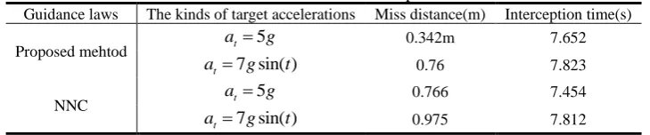
v +0.3.The simulation curves of the missile-target are shown in Figs.2(a)-(f). Table 1 presents the miss distances for two cases, and also reveals interception timesTable 1 Miss distances and interception times
Guidance laws The kinds of target accelerations Miss distance(m) Interception time(s)
Proposed mehtod at=5g 0.342m 7.652
7 sin( ) t
a = g t 0.76 7.823
NNC at=5g 0.766 7.454
7 sin( ) t
a = g t 0.975 7.812
Fig.2(a)-Fig.2(b) show the relative distance and the trajectories of missile and target under the two
control strategies, respectively. And the missile can accurately intercept the targets. From Table 1, we
can see that proposes the miss distance of the guidance method when actuator failure occurs in this
paper is 0.342 m, which is more precise than the miss distance of 0.76m by the NNC. It can be clearly
seen from Fig. 2(c) that for the constant target maneuvers, under the two control schemes, in the initial
stage the line-of-sight angle rate can quickly and smoothly converge to the expected neighborhood of
expected values. However, under the NNC guidance law the line-of-sight angle rate curve has a large
chattering during the convergence process, which will cause a large miss distance (see Table 1). In Fig.
2(d)-Fig. 2(e), the curves of the angle of attack and the pitch angular rate the missile under two
guidance strategies are respectively shown. From the results, it can be observed clearly that the angle of
attack and pitch angular can meet within the expected value range during the control process under the
proposed method, however, the angle of attack under the action of NNC does not meet the state
constraint z2 10 . In Fig. 2(e), the curves of deflection angle under the two guidance laws are given.
It can be seen that the deflection angle is bounded in the whole control process without chattering
which meet the requirement of input saturation compare with NNC.
Based on the results presented in Fig. 2, it can be concluded that the missile can realize accurately
intercepting constant maneuvering target using the adaptive dynamic surface fault-tolerant controller
0 1 2 3 4 5 6 7 8 0 100 200 300 400 500 600 700 800 900 1000 time(s) R e la ti ve d ist a n ce ( m ) NNC Proposed method
0 1 2 3 4 5 6 7 8 9
16 16.2 16.4 16.6 16.8 17 17.2 17.4
Tack of Missile and Target
X (km) Y ( km ) Missile NNC Proposed method
(a) Relative distance (b) Trajectories of missile and target
0 1 2 3 4 5 6 7
0 50 100 150 200 250 time(s) V q (m /s ) NNC Proposed method
0 1 2 3 4 5 6 7 8
-20 -15 -10 -5 0 5 10 15 20 25 30 time(s) A tt a ck A n g le (d e g re e ) NNC Proposed method upper bound lower bound
(c )Curve of the line-of-sight angle rate (d) Curve of the angle of attack
0 1 2 3 4 5 6 7 8
-150 -100 -50 0 50 100 150 200 time(s) p it ch r a te (d e g re e /s ) NNC Proposed method
0 1 2 3 4 5 6 7 8
-30 -25 -20 -15 -10 -5 0 5 10 time(s) A ct u a to r D e fl e ct io n (d e g re e ) NNC Proposed method
(e) Curve of the angle pitch rate (f) Curve of the deflection angle Fig. 2 Comparison results under these two guidance laws for case 1
(2)Simulation analysis for snake maneuvering
The control parameters in the simulation analysis of case 2 are the same as in case 1, and the
simulation results are shown in Fig. 3.
In Fig.3 (a)-Fig.3 (f), the relative distance, trajectories of missile and target, the curve of line-of-sight
rate, the angle of attack and pitch rate and the curve of deflection angle are given. In Fig. 3(a)-Fig. 3(b),
it can be seen that under two control strategies, the maneuver target of snake form has a small miss
distance and a precise intercept snake target. From Fig. 3(c) it can be seen that the curve of line-of-sight
rate converge to a small neighourhood of zero rapidly in finite time, according to the parallel approach
that the change range of both the angle of attack and the pitch rate can meet the physical constraint
requirements. It can be seen from Fig. 3(f), the compensation term of input constraints is introduced in
the proposed method. Compared with NNC, the deflection angle has a smoother and meets the physical
requirements of the actuator.
In summary, the guidance strategy designed in this paper is effective for different maneuver target
forms.
0 1 2 3 4 5 6 7 8
0 100 200 300 400 500 600 700 800 900 1000
time(s)
M
iss(
m
)
NNC Proposed method
0 1 2 3 4 5 6 7 8 9
16 16.2 16.4 16.6 16.8 17 17.2
17.4 Tack of Missile and Target
X (km)
Y
(
km
)
Missile NNC Proposed method
(a) Relative distance (b) Trajectories of missile and target
0 1 2 3 4 5 6 7
0 50 100 150 200 250
time(s)
V
q
(m
/s
)
NNC Proposed method
0 1 2 3 4 5 6 7 8
-20 -15 -10 -5 0 5 10 15 20 25 30
time(s)
A
tt
a
ck
A
n
g
le
(d
e
g
re
e
)
NNC Proposed method
(c)Curve of the line-of-sight angle rate (d) Curve of the angle of attack
0 1 2 3 4 5 6 7
-40 -20 0 20 40 60 80 100 120 140
time(s)
p
it
ch
r
a
te
(d
e
g
re
e
/s
)
NNC Proposed method
0 1 2 3 4 5 6 7
-30 -20 -10 0 10 20 30
time(s)
A
ct
u
a
to
r
D
e
fl
e
ct
io
n
(d
e
g
re
e
)
NNC Proposed method
(e) Curve of the angle of pitch (f) Curve of the deflection angle Fig.3 Comparison results under these two guidance laws for case 2 5. Conclusions
actuator failure, and state constraints is studied and analyzed. The major conclusions of this paper are
as follows:
(1) By means of adopting tangent barrier Lyapunov function and auxiliary system in the dynamic
surface controller, which can handle partial state constraints and input saturation problem, respectively.
(2) For the situations of unknown upper bound of system disturbances and actuator failures, the
adaptive control is adopted to estimate the upper bound of the disturbance and actuator failures which
are not required to be known in advance, respectively.
(3) Under the designed fault-tolerant control strategy, according to the theory and simulation results
show that when the requirements of input saturation and state constraint are met and targets with
different maneuvering forms are intercepted, good guidance precision can be obtained, which indicates
the robustness and effectiveness of the designed control scheme.
Acknowledgement
The authors would like to acknowledge the financial support provided by the keypoint research and
invention program in Hunan Province of China(2018GK2014).
Conflict of Interests
The authors declare that there is no conflict of interests regarding the publication of this article.
References
[1] Guo, J., Xiong Y, Zhou J. “A new sliding mode control design for integrated missile guidance
and control system,” Aerospace Science and Technology, Vol.78,2018, pp. 54-56.
[2] Hou, M, Z. Liang, X, L., Duan, G, Z., “Adaptive block dynamic surface control for integrated
missile guidance and autopilot,” Chinese Journal of Aeronautics, Vol.26, No.3, 2013, pp.741- 750.
[3] Sun, Y, C., Ma, G, G., “Neural network-based distributed adaptive configuration containment
control for satellite formations,” Proceedings of the Institution of Mechanical Engineers, Part G:
Journal of Aerospace Engineering, Vol.232, No.12, 2018, pp. 2349-2363.
[4] Guo, Y., Guo, J, H., Song, S, M., “Back-stepping control for attitude tracking of the spacecraft
under input saturation,” Acta Astronautica, Vol.138, 2017, pp.318–325.
[5] Sun, G., Li, D., Ren, X., “Modified neural dynamic surface approach to output feedback of
MIMO nonlinear systems,” IEEE transactions on neural networks and learning systems, Vol.26,
No.2, 2015, pp.224-236.
adaptive sliding-mode control. Journal of Projectiles,” Rockets, Missiles and Guidance, Vol.29,
No. 5, 2009, pp.31-35.
[7] Dong, C, Y., Cheng, W, Y., Wang, Q., “Back-stepping sliding mode control for integrated
guidance and control design based on active disturbance rejection,” systems engineer and
electronic, Vol.37, No.7, 2015, pp.1604- 1610.
[8] Sun, X, Y., Yao, T., Wang, S, Y., “Integrated Guidance and Control Design Method Considering
Channel Coupling,” Journal of Astronautics, Vol.8, 2016, pp.937- 945.
[9] Jiang. H., Zhao. G. R., Zhao. Z. X., “Integrated guidance and control design of vehicle based on
block diagonal control,” Fight Dynamics, Vol.31, No.5, 2013, pp. 437-442.
[10] Sharma. M, Richards. N., “Adaptive, integrated guidance and control for missile interceptors,”
AIAA guidance, navigation, and control conference and exhibit, 2004, pp.690- 704.
[11] Wang. W., Zhao. B. Q., Dong. J. P., “Integrated back-stepping design of missile guidance and
control via adaptive neural network,” Aero weaponry, Vol.05, 2012, pp.13-19.
[12] Wang. J. H., Liu. L. H., Zhao. T., “Integrated guidance and control for hypersonic vehicles in dive
phase with multiple constraints,” Aerospace Science and Technology, Vol.53, 2016, pp.103-115.
[13] Zhu. J., Liu. L., Tang. G., Bao. W., “Three-dimensional nonlinear coupling guidance for
hypersonic vehicle in dive phase,” Science China Technological Sciences. Vol. 57, No.9, 2014, pp.
1824–1833 .
[14] Xu. J., “Adaptive fault-tolerant control for a class of output constrained nonlinear systems,”
International Journal of Robust and Nonlinear Control. Vol.25, No.18, 2015, pp.3732–3745.
[15] Xu. J., “Adaptive fault tolerant control for a class of input and state constrained MIMO nonlinear
systems,” International Journal of Robust and Nonlinear Control. Vol.26, No.2, 2016, pp.286–302.
[16] Sun. J. G., Song. S. S. M., Li. P., “Adaptive anti-saturation fault-tolerant control of hypersonic
vehicle with actuator faults,” Proceedings of the Institution of Mechanical Engineers, Part G:
Journal of Aerospace Engineering, Vol.233, No.6, 2019, pp. 2066-2083.
[17] Wang. C., Wu. Y., Yu. J., “Barrier Lyapunov functions-based dynamic surface control for
pure-feedback systems with full state constraints,” IET Control Theory & Applications, Vol.11,
No.4, 2016, pp.524–530.
[18] Sun. J. G., Xu. S. Li. Song. S. M., Dong. X. J., “Finite time tracking control of hypersonic
[19] Sun. J. G., Song. S. M., Wu. G. Q., “Tracking control of hypersonic vehicle considering input
constraint”, Journal of Aerospace Engineering, Vol.30, No.6, 2017, pp.1-13.
[20] Guo. Y., Huang, B., Wang, S., “Adaptive Finite-Time Control for Attitude Tracking of Spacecraft
under Input Saturation,” Journal of Aerospace Engineering, Vol.31, No.2, 2017.
[21] Dong, W., Farrell, J, A., Polycarpou, M, M., “Command filtered adaptive backstep-ping. Control
Systems Technology,” IEEE Transactions on, Vol.20, No.3, 2012, pp.566–580.
[22] Farrell. J., Sharma. M., Polycarpou. M., “Back-stepping-based flight control with adap-tive
function approximation,” Journal of Guidance, Control and Dynamics, Vol. 28, No.6, 2005,
pp.1089–1102.
[23] Lee. C., Kim. T., Tahk. M., “Polynomial guidance laws considering terminal impact angle and
acceleration constraints,” IEEE Transactions on Aerospace and Electronic Systems, Vol.49, No. 1,
2013, pp.74-92.
[24] Wang. W. H., Xiong. S., “Three dimensional impact angle constrained integrated guidance and
control for missiles with input saturation and actuator failure,” Aerospace Science and Technology,
Vol.53, 2016, pp.169-187.
[25] Fathi. J. M, Ashrafifar. A., Mohsenipour. R., “Adaptive integrated guidance and fault tolerant
control using backstepping and sliding mode,” International Journal of Aerospace Engineering,
2015.
[26] Liu, W., Wei, Y., Hou, M., “Integrated guidance and control with partial state constraints and