UDC: 004.4:616.2
Software Tools for Generating CFD Simulation Models of Blood Flow
from CT Images, and for Postprocessing
D. Milašinović*1, M. Ivanovic1, H. Tengg-Kobligk5,6, D. Böckler4, N. Filipović1,2,3
1 Bioengineering Research and Development Center – BioIRC, Kragujevac, Serbia 2 Faculty of Mechanical Engineering, University of Kragujevac
3 Harvard School of Public Health, Harvard University, USA
4 Vascular and Endovascular Surgery Ruprecht-Karls University Heidelberg, Germany; 5 Department of Radiology, German Cancer Research Center, Germany;
6 The Ohio State University, Department of Radiology, Columbus, USA
* Corresponding author
Abstract
Modern medical image devices provide data which are suitable for computer modeling. Using the data from a multi-slice 64-CT scanner at German Cancer Research Center in Heidelberg, we developed a set of software tools for manipulating FE mesh as well as post-processing. In this work we employed raw data from the CT image device to create a 3D brick mesh of the aorta. The aorta image was taken from a patient that had an aorta aneurysm so we virtually removed it and created a corresponding 3D meshed model without the aneurism. Finite element calculation was performed for both geometrical models, for the aorta with and without aneurysm.
We also created a set of post-processing software tools for representation of the results. It is shown that the developed software tools are efficient regarding the post-processing time. This efficiency is very important for future diagnostic and modelling software.
Keywords: 3D modeling, CFD simulation, mesh, brick mesh, STL, post-processing
1. Introduction
Cardiovascular diseases are common and enormous efforts are needed in curing them. Diagnostics is very important in planning adequate interventions. Modern medical image devices provide data that can be used for 3D computer modeling, where geometrical modeling is the base for computational simulations.
Computer simulations can be very useful because we can simulate and modify physical (boundary) conditions and results (as shear stress, velocities and pressure distributions) without real interventions on a specific patient. This could open a new avenue in predictive medicine where we can help in predicting what could later happen in a particular organ of a specific patient.
taken from a patient who had the aorta aneurysm. We used .STL mesh format to create a 3D brick mesh of the aorta to further proceed in finite element calculation. Our next step was to remove the aneurysm from the aorta (by modifying boundary surface mesh) and to create a new aorta mesh model using the same finite elements (3D brick). The calculation was performed on both models with the same input boundary conditions. For presentation of the results, we created a set of post-processing software.
2. Geometrical modeling
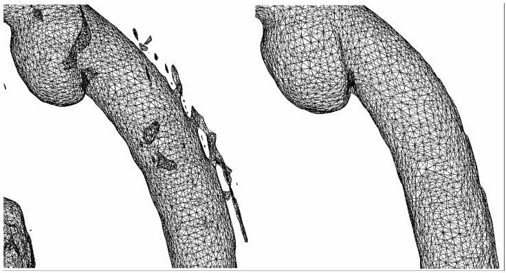
Firstly, we prepared the original .STL file (Fig. 1) for 3D meshing. Due to the threshold of medical image device, a number objects were present. We classified them into two categories:
a) objects that are independent
b) objects that are attached to the main object (aorta)
Fig. 1. Model .STL before and after removing unnecessary objects.
The first step in geometrical modeling was to remove independent external objects. We used (C.Geuzaine et al. 2008) for this procedure. In the process of removing the external objects that are attached to the main aorta we used software tools that we developed in C++. The input for this software is .STL surface triangle mesh with the hole, and the output is surface mesh without the hole. In our software we used COG (center of gravity) algorithm for patching the holes (D.Milašinović et al. 2008). After the removal of external objects we obtained a nice smooth surface of the main object - aorta (Fig. 1).
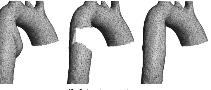
After completing the desired geometry for this aorta model, we proceeded to virtually remove the aneurysm. This removal was semi-automatic, because we manually set the connection nodes (Fig. 2).
Fig. 2. Aneurism removal.
3. Mesh
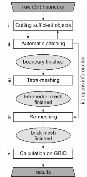
Fig. 3. The complete computational procedure.
After 3D meshing, the input boundary conditions were prescribed (e.g. input and output fluid velocity profiles), the FE calculation was performed. For both aorta models the mesh independence was reached at 350000 to 680000 finite elements.
4. Results
The calculation was executed on GRID, on 20 computational nodes. The calculation was performed for both aorta models. To create a user-friendly presentation of the results, we developed a set of post-processing software tools. Originally our PAK-F (M.Kojić et al. 1998) solver prints a UNV file format, and we used an in-home software for 3D drawings. In one FE model calculation 50 GB of data were written in a number of UNV files (usually one UNV file per time step). A problem with this UNV file is that all physical quantities are written in one file, and we found that the POS format is more useful for large models, so we created converters from the UNV to POS. The POS is also a standard post-processing format, where the POS prints one file for one physical quantity.
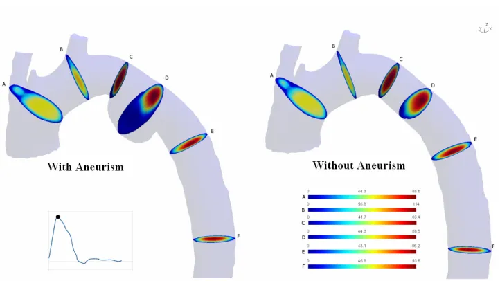
Fig. 4. Velocity profile for a peak systole phase for Case I (aorta with aneurysm) and Case II (aorta without aneurysm) .
Fig. 6. Velocity profile for a diastole phase for Case I (aorta with aneurysm) and Case II (aorta without aneurysm) .
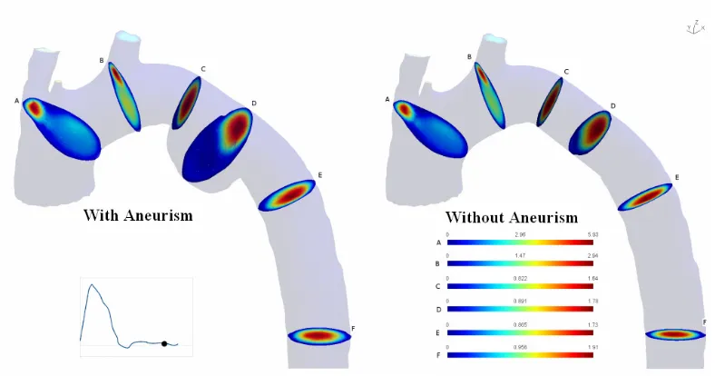
Fig. 8. Distribution of the wall shear stress magnitude along the aorta with branches, at the peak systolic flow for Case I (aorta with aneurysm) and Case II (aorta without aneurysm) .
Fig. 9. Distribution of the wall shear stress magnitude along the aorta with branches, at the diastolic flow for Case I (aorta with aneurysm) and Case II (aorta without aneurysm) .
5. Conclusion
and informatics) will lead to further fast development of computer simulation tools for general use in clinical investigations and practice.
Acknowledgments
This research was supported by Ministry of Science of Serbia, TR12007 and OI144028.
References
D.Milašinović, M.Ivanović, N.Filipović, M.Kojić, 2008, Software tools for automatic generation of finite element mesh and application of biomechanical calculation in medicine; Hemijska industrija, 62(3):177-180
C.Geuzaine, J.-F. Remacle, 2008, Gmsh: A three-dimensional finite element mesh generator with built-in pre- and post-processing facilities. http://geuz.org/gmsh/
Hang Si, Tetgen, 2007, A Quality Tetrahedral Mesh Generator and Three-Dimensional Delaunay Triangulator, Research Group: Numerical Mathematics and Scientific Computing Weierstrass Institute for Applied Analysis and Stochastics Mohrenstr. 39, 10117 Berlin, Germany. http://tetgen.berlios.de/