BREAK PRECLUSION CONCEPT AND ITS APPLICATION TO THE
EPRTM REACTOR
S. Chapuliot, C. Migné
AREVA-NP, Tour AREVA – 1, place Jean Millier, 92084 Paris La-Défense, France E-mail of corresponding author: [email protected]
ABSTRACT
This paper provides a synthesis of the technical basis supporting the Break Preclusion concept and its implementation on the Main Coolant Lines and Main Steam Lines of the EPRTM reactor. In a first step, it describes the background of the Break Preclusion concept, and then it details the requirements associated to its implementation in a Defense In Depth approach.
In second steps, main benefits and few illustrative examples are given for the MCL.
INTRODUCTION
Break Preclusion concept is applied in standard EPRTM design under construction in Flamanville and in Taishan. It emerged during the early phase of EPRTM design with the objective to deterministically rule out the catastrophic failure (i.e. Double-Ended Guillotine Break) of the Main Coolant Lines and the Main Steam Lines from the list of design events considered for structures and components.
Due to this position, Break Preclusion concept can not be separated from the design itself. In additions, it integrates manufacturing and surveillance consideration. It follows a Defense In Depth approach with the four following main steps:
- Best practices for design and manufacturing, knowledge and prevention of potential damages; - Improved surveillance capabilities;
- Systems to detect and mitigate incidental situations; - Limiting consequences of unexpected failure.
Those essential aspects concurring to the Break Preclusion mechanical demonstration are successively reviewed in this article, first through the explanation of the general background, then through examples for the Main Coolant Lines. The following points are treated:
- The Background principles of the Break Preclusion concept; - The main technical elements of the demonstration;
- The position of Leak-Before-Break within the overall Break Preclusion demonstration; - The Benefits of Break Preclusion in terms of costs and operation.
HISTORICAL BACKGROUND AND BASES OF BREAK PRECLUSION CONCEPT
Break Preclusion concept emerged during EPRTM Basic Design development with the objective to satisfy regulatory requirements of France and Germany, without remaining confined to current design rules but taking advantage of:
- operating experience feedback from the previous generation of plants (German Konvoï and French 900 to N4 plants),
- advances in the state of the art in manufacturing, engineering design and safety analysis,
in order to formulate the technical requirements for the new plants. At that time, the Konvoï plant design had already implemented break exclusion criteria that were based on the quality of design, materials and workmanship, supplemented by best-inclass surveillance systems.
French and German regulators were of course involved in this process, together with the French and German utilities as future Plant Owners. Shortly afterwards, the main European utilities started developing their common European Utility Requirements (EUR) for the new generation of plants and incorporated the Break Preclusion concept.
General definition of Break Preclusion
"Break preclusion is a concept, implemented during the design phase, to deterministically rule out the catastrophic failure of any important coolant line (e.g. main coolant line) from the list of the design events
considered for structures and components"
Hence Break Preclusion cannot be separated from the design itself. Of particular importance at this stage is the notion that breaks can be precluded by design, and through adequate in-service surveillance.
Technical guideline for EPRTM reactor
As stated before, French Safety Authority was involved in the development process and issued a "Technical Guidelines (TG)" [2] defining the safety philosophy and approach as well as the general safety requirements to be applied for the design and manufacturing of the next generation of pressurized water reactor (PWR). These TG were based on common work of French and German Safety Authorities technical supports (IRSN and GRS), discussed then adopted by French/German experts in a plenary meeting held in 2000, addressed by French Safety Authority (ASN) to French Utility. This document states:
- The necessity of a significant improvement of the safety level of future plants compared to existing ones;
- The choice of evolutionary approaches taking into account large operating feed back, results of in-depth studies of the existing plants and benefit from innovative features as well as R&D activities (in particular for severe accidents).
TG states that for high quality levels achieved in design, material choice, manufacturing, inspection and surveillance during operation are adequate conditions, complete guillotine break of large pipes of the Main Coolant Lines (MCLs) and Main Steam Lines (MSLs) between the steam generators and the first isolation devices located outside the reactor building can be ‘excluded’.
Noteworthy is the fact that the “Leak-Before-Break (LBB) type” demonstration, which is at the heart of the break elimination in US regulatory requirements, is of secondary importance according to the French regulatory framework, compared to the quality of the product as-installed and the assurance of adequate surveillance.
In the Defense-In-Depth (DID) approach, regarding the consideration of Double-Ended Guillotine Break (DEGB) as an accident initiator for the design of safeguard systems, the TG allows for “realistic assumptions” to be considered in the boundary conditions and failure assumptions. Notably, the failure of large SIS check valves in conjunction with DEGB event needs not be assumed, owing to the good reliability of those components and the unlikely instantaneous DEGB.
The EUR requirements
EUR documents aim at harmonization and stabilization of the conditions in which the standardized Light Water Reactors nuclear power plants to be built in Europe will be designed and developed. The group is constituted by the major European companies involved in electricity generation from nuclear power in Europe and expects to improve both nuclear energy competitiveness and public acceptance in an electricity market unified at European level. The EUR definition of Break Preclusion has been provided through the reference document [1]. In this document, BP is achieved through a combination of:
- High quality material selection; - Low stress design;
- In-service inspection; - “LBB type” demonstration.
The latter element refers to a conventional (but robust) demonstration of structural integrity assessment through progressive steps of increasing levels of unlikelihood:
- Demonstration that there are no active degradation mechanisms or unanticipated loads likely to create damage during service. This first step refers to a good knowledge of loadings, potential degradation mechanism and materials behavior with time.
- Assumption of inner surface defects of a detectable size (through in-service inspection), and demonstration that crack growth would be moderate over the life of the plant. This second step is linked to the capability of in-service inspection system to detect part-through crack-like defects.
with a through-wall detectable flaw size derived from the capability of leak detection systems. In this demonstration, appropriate safety margins have to be demonstrated on both crack size and leak rate. The EPRTM has received a full re-certification of compliance to EUR in July 2009.
Utility requirements for Flamanville 3 Plant
For the first French EPRTM reactor built in France, EDF has issued a document translating the requirements of the TG as well as other French regulation into a technical guidance document. The AREVA BP methodology for the Standard EPRTM, described in the article is in compliance with this specification document.
GENERAL DEFENSE IN DEPTH PRINCIPLES
The DID principle is often invoked in the TG as well as the EUR and EDF documents. The DID principle is defined in [3] as follows:
“Application of the concept of defense in depth in the design of a plant provides a series of levels of defense (inherent features, equipment and procedures) aimed at preventing accidents and ensuring appropriate protection in
the event that prevention fails.”
The five different levels of DID extracted from IAEA definitions [3] are recalled below:
1. Prevention: “The aim of the first level of defense is to prevent deviations from normal operation, and to prevent system failures. This leads to the requirement that the plant be soundly and conservatively designed, constructed, maintained and operated in accordance with appropriate quality levels and engineering practices, such as the application of redundancy, independence and diversity”.
2. Surveillance: “The aim of the second level of defense is to detect and intercept deviations from normal operational states in order to prevent anticipated operational occurrences from escalating to accident conditions. This is in recognition of the fact that some Postulated Initiating Event (PIE) are likely to occur over the service lifetime of a nuclear power plant, despite the care taken to prevent them.”
3. Mitigation of Design Basis Conditions: “For the third level of defense, it is assumed that, although very unlikely, the escalation of certain anticipated operational occurrences or PIEs may not be arrested by a preceding level and a more serious event may develop. These unlikely events are anticipated in the design basis for the plant, and inherent safety features, fail-safe design, additional equipment and procedures are provided to control their consequences and to achieve stable and acceptable plant states following such events.”
4. Mitigation of Design Extension Conditions: “The aim of the fourth level of defense is to address severe accidents in which the design basis may be exceeded and to ensure that radioactive releases are kept as low as practicable. The most important objective of this level is the protection of the confinement function. The protection provided by the confinement may be demonstrated using best estimate methods.”
5. Mitigation of Radioactive Releases: “The fifth and final level of defense is aimed at mitigation of the radiological consequences of potential releases of radioactive materials that may result from accident conditions.”
APPLICATION OF THE DID PRINCIPLES TO BREAK PRECLUSION
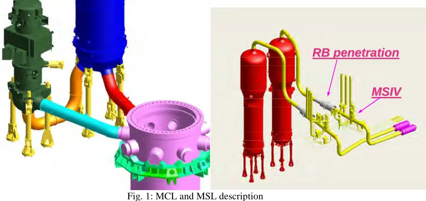
The BP concept was applied to MCLs and MSLs (inside the Reactor Building and outside up to the fixed point downstream the Main Steam Isolation Valve – MSIV) according to the Technical Guidelines sections B.1.2 and B.1.3 [2] (see fig. 1) and following the DID approach. BP is a design demonstration involving regulatory, design, manufacturing, controls and in-service inspection requirements, enabling not to consider in the plant design basis PIEs resulting from the complete rupture of MCL and MSLs. It can be considered as an enhancement of the 3 first levels of the DID (Prevention, Surveillance and Mitigation) in order to relax constraints for level 4 of DID (Mitigation of Design Extension Conditions). It has no link to the level 5 of the DID principle.
The following sub-chapters give the detail of the requirements which are mandatory to implement the BP concept for EPRTM plant.
Prevention: design, materials and manufacturing
Concerning design, the highest level of quality is required in accordance with the design codes, material selection and stress analysis. In particular, assessment of the damage mechanisms that are part of the structural integrity demonstration must be comprehensive and continuous over the unit’s service life. This assessment must demonstrate that significant degradation caused by such mechanisms can be ruled out. The degradation mechanisms in which the kinetics cannot be reliably modeled or which could result in very long (or axi-symmetric) defects must be taken into consideration or ruled out.
RB penetration
RB penetration
MSIV
MSIV
RB penetration
RB penetration
MSIV
MSIV
Fig. 1: MCL and MSL description
All potential and predictable degradation mechanisms are assessed at design stage. Periodic updating of these assessments is performed using operational plant experience feedback from other units, both nationally and internationally. The completeness of the degradation mechanisms considered is confirmed on the basis of this analysis. It is intended to be updated at each Periodic Safety Review. The following points are considered as a minimum:
- Fatigue: the assessment covers pipework fatigue for the operating conditions, thermal fatigue and vibratory fatigue. The usage factor must be lower than 1 for the unit full service life (60 years), but in practice it remains lower than 0.1;
- Fast fracture risk, including consideration of the effects of ageing (notably thermal ageing): the risk of brittle fracture is ruled out as there is sufficient toughness in the materials;
- Erosion-corrosion: the choice of materials shall ensure protection against risks of this type;
- Corrosion: the assessment primarily focuses on cracking by inter-granular stress corrosion, and may refer to operational experience feedback, including control of the chemical composition of the system fluids under consideration;
- Erosion: the assessment may refer to operational experience feedback of similar installations.
In order to satisfy all these requirements, materials used are those already in use for similar pipework systems on operational nuclear units, characterized as having satisfactory performance. However, other materials may be used provided the appropriate justifications are made. For that, are required:
- Use of high quality materials, providing good toughness and strength, over the entire range of operating temperatures, and which are not unduly sensitive to corrosion and erosion-corrosion degradation mechanisms; - Sample tests are performed to ensure that the mechanical properties of the base materials and the welded joints
comply with the minimum values assumed at the design phase.
Concerning manufacturing, the highest level of quality must be obtained via the specification procedures, quality control and the acceptance criteria for Non Destructive Examination (NDE). Additionally:
- Large diameter nozzles shall be either extruded or integrally forged and not set in by welding;
- All welds must be examined at the end of the manufacturing phase in order to demonstrate the absence of weld under-fills and any significant defects. The size of these defects must be lower than that considered in the mechanical stability and integrity demonstrations;
- For ferritic steel, the as-manufactured thickness must be verified during acceptance inspections for reducers and elbows.
Surveillance: In-service inspection and monitoring
The second level of DID is ensured by In-Service Inspection program, the monitoring during normal operation and the leakage detection.
In-Service Inspection (ISI) aims firstly at demonstrating that the predictions of the risk of damage to pipework remain within the design provisions and hypotheses. It must also be demonstrated that no degradation appears which was not foreseen in the analysis of potential degradation mechanisms.
To apply the BP concept, accessibility and ability to inspect each point on the relevant pipework is required. In particular, provisions are made to enable volumetric inspection of all the welds, and around those nozzles where the likelihood to develop degradation mechanisms is relatively higher.
Dissimilar metal welds must be able to be inspected by preferably two volumetric methods. If it can be demonstrated that one method is able to detect all relevant degradation mechanisms, it is acceptable to use only one method.
In-Service Inspection program must be established according to those principles; it is nevertheless a shared responsibility between the Plant Designer and the Plant Owner who has to endorse it.
Generally, operational monitoring must be carried out in order to ensure that the operation remains within the conservative assumptions taken at the design stage, notably with regard to:
- Stresses, by monitoring movements of main components and pipes, clearance at component supports, displacements at self-locking devices, as well as vibration levels, during hot functional tests.
- Fatigue damage: as a minimum, by recording the transient history of the reactor coolant system and main steam lines.
- Monitoring of the RCS chemistry in order to prevent corrosion.
Application of the BP concept does not lead to more restraining requirements in comparison with usual monitoring applied for plants in operation. It is however a mandatory element.
The leakage monitoring will allow detecting leakages of the MCLs and MSLs in order to shutdown the plant before an aggravation of the initial leakage. The leak detection sensitivity is to be sufficient to satisfy the margin requirements defined by the BP concept. The leakage instrumentation has also to comply with the usual regulation (NRC RG 1.45).
Mitigation of design basis conditions
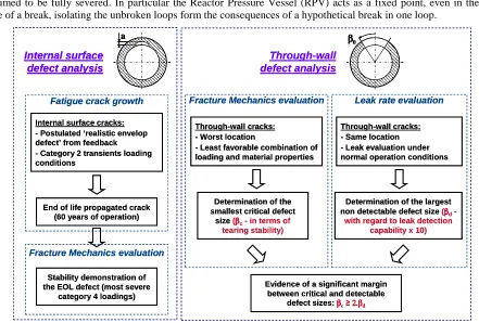
In order to comply with the 3rd level of DID principle, complementary structural integrity and in particular fracture mechanics analyses are performed (fatigue crack propagation, crack stability, leakage rate and assessment of margins). Although similar in purpose, it is not fully identical to the LBB analysis procedure per USNRC rules as defined in Reference [4]. Two main steps are performed within this demonstration (fig. 2):
- Integrity analysis of a postulated inner surface crack in welds (‘realistic envelope defect’ from the experience feedback on French PWR). The fatigue crack growth analysis is done considering the transients of category 2 loading conditions by determining the surface point and deepest point propagation for 60 years of operation and using the crack growth laws for a PWR environment.
The End-Of-Life (EOL) circumferential defect must remain stable (in terms of tearing stability criteria of the RSE-M [5]) under the most severe loadings (category 4 loading conditions).
- Determination of the smallest through-wall critical defect in the piping under maximum anticipated loads (through-wall crack stability analysis). Sufficient margins have to be exhibited between this critical crack and the leakage crack (through-wall crack whose size is related to the minimum leak rate capabilities under full power operating conditions). Conventional margins of 2 on crack size and 10 on leak rate evaluation are applied in this demonstration.
Mitigation of Design Extension Conditions
- Events resulting from DEGB of a BP lines are no longer postulated as PIE in the deterministic safety demonstration, and are replaced by the events resulting from the complete rupture of the largest connected piping for which BP is not implemented.
- The anti-whip devices designed to limit the pipe whipping in case of a DEGB of a BP line are not installed.
However, DEGB remains a part of the safety demonstration with the following considerations:
- DEGB of the MCLs is considered in the safety analyses under realistic assumptions, for the design of the safety injection system and the containment, and for the qualification of equipment used in accidental conditions (Safety Injection Systems for example).
- DEGB of the MSLs is also considered as an enveloping PIE for containment design and qualification of equipments.
- The stability of the large components and their supports is reinforced by applying a conventional static load of 2pA at each equipment nozzle (where p is the system’s nominal pressure), with the nozzle-to-pipe connection assumed to be fully severed. In particular the Reactor Pressure Vessel (RPV) acts as a fixed point, even in the case of a break, isolating the unbroken loops form the consequences of a hypothetical break in one loop.
Evidence of a significant margin between critical and detectable
defect sizes: ββββc≥OKOKOKOKββββd
Through-wall cracks: - Worst location
- Least favorable combination of loading and material properties
Determination of the smallest critical defect
size (ββββc- in terms of
tearing stability)
Fracture Mechanics evaluation
Through-wall cracks: - Same location - Leak evaluation under normal operation conditions
Determination of the largest
non detectable defect size (ββββd
-with regard to leak detection capability x 10)
Leak rate evaluation ββββ0 Through-wall defect analysis Internal surface defect analysis a
Internal surface cracks: - Postulated ‘realistic envelop defect’ from feedback - Category 2 transients loading conditions
End of life propagated crack (60 years of operation)
Fatigue crack growth
Fracture Mechanics evaluation
Stability demonstration of the EOL defect (most severe
category 4 loadings)
Evidence of a significant margin between critical and detectable
defect sizes: ββββc≥OKOKOKOKββββd
Through-wall cracks: - Worst location
- Least favorable combination of loading and material properties
Determination of the smallest critical defect
size (ββββc- in terms of
tearing stability)
Fracture Mechanics evaluation
Through-wall cracks: - Same location - Leak evaluation under normal operation conditions
Determination of the largest
non detectable defect size (ββββd
-with regard to leak detection capability x 10)
Leak rate evaluation ββββ0 ββββ0 Through-wall defect analysis Internal surface defect analysis a Internal surface defect analysis a a
Internal surface cracks: - Postulated ‘realistic envelop defect’ from feedback - Category 2 transients loading conditions
End of life propagated crack (60 years of operation)
Fatigue crack growth
Fracture Mechanics evaluation
Stability demonstration of the EOL defect (most severe
category 4 loadings)
Fig. 2: Overview of the LBB type demonstration
COST AND OPERATIONAL BENEFITS
At the design and construction stage, a realistically sized concrete building, including accumulator sizing for DEGB of the MCLs with realistic assumptions, reaps non-negligible cost benefits.
Another undisputable cost benefit of BP is the avoidance of pipe-whip restraints which are large ‘supporting’ steel structures with special anchorage (often through-floor) owing to the magnitude of pipe break loads. Those steel structures do not physically support anything but are there for the hypothetical case of DEGB only. They are often of a complex design, due to the need to provide adjusting shims to fulfill stringent requirements on gaps. Energy dissipation capability (for shock absorption) also adds to the complexity and cost. But the removal of those pipe whip restraints constitutes also a benefit for an operational point of view:
- Pipe whip restraints significantly reduce accessibility to the welds for inspection. Not only is this potentially detrimental to the quality of inspections, but it also increases the time required for conducting those inspections and generates additional dose to the personnel.
- Very small gaps at pipe whip restraints create the risk of thermal interference if the gap shimming has been wrongly performed or due to a foreign object or by inadvertent movement of shim plates or collars. Such incident of thermal binding of primary loop piping against a cross-over leg restraint has already been reported in the past at a US plant. It is of high safety importance that the primary loops and steam lines expand freely during power ascension.
- A consequence of the congestion issue mentioned above is that the length of class 1 lines is significantly increased when BP is not applied and MCL pipe whip restraints are installed, due to the lack of space to install the isolation valves. A more complex layout and increased number of welds is an undesirable consequence of DEGB postulation.
Operationally speaking, the application of BP on the MSL may somewhat increase the maintenance requirements associated with inspection and calibration of Leak Detection System inside and outside Containment, but this comes with a clear safety benefit of an improved detection of leaks and an improved prevention against catastrophic pipe failures.
In addition, there can be no safety reduction associated with the elimination of an arbitrary and unrealistic scenario of instantaneous “guillotine” break of large ductile piping. With BP it becomes coherent to assume a failure probability of MCL or MSL in the same range as for the RPV or other large primary equipment. For the same reason, consideration of realistic assumptions in conjunction with DEGB postulation is fully justified. This is evidenced by the fact that DEGB, as an accident initiator, contributes very little to the overall core damage frequency.
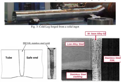
Fig. 3: Cold Leg forged from a solid ingot
Tube Safe end
Tube Safe end
ER316L stainless steel weld Low Alloy SteelLow Alloy Steel
Ni- base Alloy 52 Ni- base Alloy 52
Stainless Steel cladding Stainless Steel
cladding
Stainless Steel 316L Stainless Steel
316L Low Alloy Steel
Low Alloy Steel Low Alloy Steel Low Alloy Steel
Ni- base Alloy 52 Ni- base Alloy 52 Ni- base Alloy 52 Ni- base Alloy 52
Stainless Steel cladding Stainless Steel
cladding Stainless Steel
cladding Stainless Steel
cladding
Stainless Steel 316L Stainless Steel
316L Stainless Steel
316L Stainless Steel
316L
Fig. 4: Homogeneous stainless steel weld (left) & Dissimilar Metal Weld (right)
EXAMPLES FOR THE MAIN COOLANT LINES
This chapter gives few examples of improvements adopted in EPRTM MCL design, materials and manufacturing processes selected to yield a high quality required for BP and to improve inspectability. These are the following:
- Main nozzles for auxiliary lines (SL, SIS, RHRS, CVCS) are machined out of the forgings. Doing this, the number of girth welds significantly reduced (9 homogeneous welds + 4 dissimilar metal welds per loop – see fig. 3).
- Forging processes are optimized to obtain both the required mechanical properties and a good ultrasonic permeability (grain size requirements).
- Girth welds as well as Dissimilar Metal Welds were performed by an automatic narrow gap TIG welding, reducing significantly the risk of lack of fusion and providing high toughness properties.
o One pass per layer (see fig. 4): reproducible processes and reduction of input energy which provides reduction of residual stresses, low wall dilution (in case of DMW), reduction of potential defects and improvement of controllability.
o Use of improved filler material grades for thermal ageing and corrosion.
o Use of Inconel 52 (in case of DMW) which has an intermediate thermal expansion coefficient between ferritic and austenitic steels and thus reduces stresses due to thermal expansion.
- Homogeneous welds can be inspected by at least one volume inspection method and dissimilar welds by two volume inspection methods. The place to manage these controls is ensured by design.
CONCLUSIONS
This article gives an overview of the Break Preclusion concept applied in EPRTM reactor for Main Coolant Lines and Main Steam Lines, in order to exclude their Double-End-Guillotine-Break scenario from design basis.
Based on Technical Guidelines and reference documents issued by safety authority and European utilities, the developed concept is following a Defense-In-Depth approach fully integrated in the design. Main requirements are the following:
- Prevention at design, choice of materials and manufacturing stages through a good knowledge of potential degradations, choice of materials in adequacy with those potential damages and the use of best practice manufacturing processes and quality control.
- Improved surveillance capability, monitoring of transients, improved leak detection during service.
- LBB type of demonstration with evaluation of fatigue crack propagation of a potential non detected inner surface defect, then tearing stability evaluation of the corresponding End Of Life defect and the largest non detectable defect (in terms of leakage capability).
All these requirements, corresponding to the 3 first levels of Defense-In-Depth are reinforced in comparison to previous nuclear plant generation. On this basis, at fourth level, requirements are less severe with events resulting from Double-End-Guillotine-Break removed from the basic design of components. However DEGB remains at this level of DID, but considering realistic assumptions for the containment and Safety Injection Systems design, the large components stability analysis and supports design. Main benefits in terms of costs and operation resulting from the Break Preclusion concept are evoked in the article. It is principally:
- A reduction of concrete structures costs with consideration of ‘realistic DEGB’.
- Removal of pipe-whip restraints and, as a consequence, simplification of pipe lines, reduction of maintenance operation (gap adjustment and accessibility), improvement of the accessibility (inspection), removal of potential pipe restraint under thermal load and reduction of man exposure to radiation.
ACKNOWLEDGEMENTS
The authors would like to thanks all the contributors of the internal report which constitutes the background of the article, in particular: P.Monette, F.Bouteille, V.Besnard, Y.Guegan, P.Ould, J.M.Tchilian, A.Balthasar.
REFERENCES
[1] European Utility Requirements for LWR Nuclear Power Plants (Vol.2, Chap.4, Section 5.10), Rev. C.
[2] Letter DSNR SD2 0729/2004 du 28/09/04: Safety Options for the EPR Project – Technical Guidelines for the design and construction of the next generation of nuclear power plants with pressurized water reactor adopted during GPR/German experts plenary meetings held on October 19 and 26 (2000).
[3] IAEA Safety Standard NS-R-1 ‘Safety of Nuclear Power Plants – Design’
[4] USNRC NUREG 0800, Standard Review Plan, Section 3.6.3, Leak-Before-Break evaluation procedures, Rev.1, March 2007