585-310-251
Comcode 108185224
Issue 2
December 1997
I
NTUITY
Messaging Solutions
Release 4
Notice
Every effort was made to ensure that the information in this book was com-plete and accurate at the time of printing. However, information is subject to change.
Your Responsibility for Your System’s Security
Toll fraud is the unauthorized use of your telecommunications system by an unauthorized party, for example, persons other than your company’s employees, agents, subcontractors, or persons working on your company’s behalf. Note that there may be a risk of toll fraud associated with your tele-communications system and, if toll fraud occurs, it can result in substantial additional charges for your telecommunications services.
You and your system manager are responsible for the security of your sys-tem, such as programming and configuring your equipment to prevent unau-thorized use. The system manager is also responsible for reading all installation, instruction, and system administration documents provided with this product in order to fully understand the features that can introduce risk of toll fraud and the steps that can be taken to reduce that risk. Lucent Tech-nologies does not warrant that this product is immune from or will prevent unauthorized use of common-carrier telecommunication services or facili-ties accessed through or connected to it. Lucent Technologies will not be responsible for any charges that result from such unauthorized use.
Lucent Corporate Security
Whether or not immediate support is required, all toll fraud incidents involv-ing Lucent products or services should be reported to Lucent Corporate Security at 1 800 821-8235. In addition to recording the incident, Lucent Corporate Security is available for consultation on security issues, investiga-tion support, referral to law enforcement agencies, and educainvestiga-tional pro-grams.
Lucent Technologies Fraud Intervention
If you suspect that you are being victimized by toll fraud and you need tech-nical support or assistance, call Techtech-nical Service Center Toll Fraud Inter-vention Hotline at 1 800 643-2353.
Federal Communications Commission Statement
Part 15: Class B Statement. This equipment has been tested and found to comply with the limits for a Class B digital device, pursuant to Part 15 of the FCC Rules. These limits are designed to provide reasonable protection against harmful interference in a residential installation. This equipment generates, uses, and can radiate radio-frequency energy and, if not installed and used in accordance with the instructions, may cause harmful ence to radio communications. However, there is no guarantee that interfer-ence will not occur in a particular installation. If this equipment does cause harmful interference to radio or television reception, which can be deter-mined by turning the equipment off and on, the user is encouraged to try to correct the interference by one or more of the following measures:
• Reorient the receiving television or radio antenna where this may be done safely.
• To the extent possible, relocate the receiver with respect to the tele-phone equipment.
• Where the telephone equipment requires AC power, plug the tele-phone into a different AC outlet so that the teletele-phone equipment and receiver are on different branch circuits.
Part 15: Personal Computer Statement. This equipment has been certified to comply with the limits for a Class B computing device, pursuant to Sub-part J of Part 15 of FCC Rules. Only peripherals (computing input/output devices, terminals, printers, etc.) certified to comply with the Class B limits may be attached to this computer. Operation with noncertified peripherals is likely to result in interference to radio and television reception.
Part 68: Network Registration Number. This equipment is registered with the FCC in accordance with Part 68 of the FCC Rules. It is identified by an FCC registration number.
vision signals to the public switched network when: • Answered by the called station
• Answered by the attendant
• Routed to a recorded announcement that can be administered by the CPE user
This equipment returns answer-supervision signals on all DID calls for-warded back to the public switched telephone network. Permissible excep-tions are:
• A call is unanswered • A busy tone is received • A reorder tone is received
Canadian Department of Communications (DOC) Interference Information
This digital apparatus does not exceed the Class A limits for radio noise emissions set out in the radio interference regulations of the Canadian Department of Communications.
Le Présent Appareil Nomérique n’émet pas de bruits radioélectriques dépas-sant les limites applicables aux appareils numériques de la class A préscrites dans le reglement sur le brouillage radioélectrique édicté par le ministére des Communications du Canada.
Trademarks
See the section titled “About This Book.”
Ordering Information
Call: Lucent Technologies Publications Center
Voice 1 800 457-1235 International Voice 317 361-5353 Fax 1 800 457-1764 International Fax 317 361-5355 Write: Lucent Technologies Publications Center
2855 N. Franklin Road Indianapolis, IN 46219 Order: Document No. 585-310-251
Comcode 108185224 Issue 2, December 1997
You can be placed on a standing order list for this and other documents you may need. Standing order will enable you to automatically receive updated versions of individual documents or document sets, billed to account infor-mation that you provide. For more inforinfor-mation on standing orders, or to be put on a list to receive future issues of this document, contact the Lucent Technologies Publications Center.
Warranty
Lucent Technologies provides a limited warranty on this product. Refer to the “Limited Use Software License Agreement” card provided with your package.
European Union Declaration of Conformity
Lucent Technologies Business Communications Systems declares that the equipment specified in this document conforms to the referenced European Union (EU) Directives and Harmonized Standards listed below:
EMC Directive 89/336/EEC Low-Voltage Directive 73/23/EEC
The “CE” mark affixed to the equipment means that it conforms to the above directives.
Comments
To comment on this document, return the comment card at the front of the document.
Acknowledgment
Contents
Page iii
Contents
Contents iii
About This Book ix
■ Purpose ix
■ Intended Audiences ix
■ Release History x
■ How to Use This Book x
For Complete Installation Instructions x For Troubleshooting Information x For More Connectivity and Pinout Information x
To Locate Specific Topics xi
■ Conventions Used in This Book xi
Terminology xi
Keyboard and Telephone Keypad Representations xiii
Screen Displays xiv
Other Typography xiv
Safety and Security Alert Labels xv
■ Trademarks and Service Marks xv
■ Related Resources xvii
Documentation xvii
Training xvii
Technical Assistance xviii
■ How to Comment on This Book xviii
1
Overview of Switch Integration withDigital Station Interface 1-1
■ Overview 1-1
■ Purpose 1-1
■ Method of Integration 1-2
Digital Station Interface Circuit Card 1-2
Ports 1-2
Station Emulation 1-2
Hunting 1-2
Contents
Page iv
■ Demarcation Points 1-5
■ Joint Acceptance Testing 1-5
■ Lucent INTUITY Features and Functionality Supported 1-5 ■ Lucent INTUITY Features and Functionality Unsupported 1-6
■ Integration Performance 1-6
■ General Configuration Requirements 1-7 ■ Checklist for Switch Integration 1-7
2
Planning for Switch Integration withDigital Station Interface 2-1
■ Overview 2-1
■ Purpose 2-1
■ Checklist for Planning 2-2
■ Determining the Number of Ports
to Use on the Digital Station Interface Circuit Card 2-3
Worksheet 2-3
Examples 2-4
■ Obtaining Terminal Numbers for Ports
on the Digital Station Interface Circuit Card 2-4
Load Leveling 2-4
Worksheet 2-4
■ Obtaining the Lucent INTUITY Message
Retrieval Number 2-5
Worksheet 2-6
■ Obtaining the Dedicated MWI Port
Extension Number (Optional) 2-6
Worksheet 2-6
■ Obtaining Extension Numbers and
ACD DNs for the Lucent INTUITY Tip/Ring Lines 2-6
Worksheet 2-7
■ Mapping Tip/Ring Extensions to Keys
on the Digital Station Interface Circuit Card Ports 2-8
Worksheet 2-9
Example 2-10
■ Determining the Call Redirection
Display Strings Currently Set on the Switch 2-11
Worksheet 2-12
■ Determining the Serial Number of the
Contents
Page v
Worksheet 2-13
■ Determining the Start and End Times
for Night Audits (If Run) 2-13
Worksheet 2-13
■ Obtaining the Day/Night Service
Automated Attendant Number (If Used) 2-14
Worksheet 2-14
■ Obtaining the Express Messaging
Automated Attendant Number (If Used) 2-14
Worksheet 2-15
■ Obtaining the Call Routing Automated
Attendant Number (If Used) 2-15
Worksheet 2-15
■ Obtaining Numbers for the Call
Routing Automated Attendant Menu (If Used) 2-16
Worksheet 2-16
■ Planning for Phantom Numbers (If Used) 2-17
Worksheet 2-17
3
Requirements and Administration for Nortel Meridian 1 and MeridianSL-1 Switches 3-1
■ Overview 3-1
■ Purpose 3-1
■ Switch Software Requirements 3-2 ■ Switch Hardware Requirements 3-2
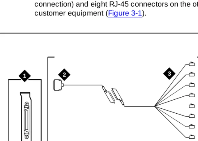
■ Connectivity 3-3
Configurations 3-4
Connecting the Lucent Digital Station Interface
Circuit Card to Customer Equipment 3-4
Custom Wiring 3-4
Connecting the Tip/Ring Lines 3-5
■ Required Switch Administration 3-6
Overlays 3-6
Verifying the Switch Software Release 3-6 Verifying the Switch Option Packages 3-6 Verifying the Attendant Console Day/Night
Contents
Page vi
Administering the ACD DNs 3-8
Administering the Tip/Ring Lines 3-8 Administering the Switch Users 3-10 Administering the Ports on the Digital Station
Interface Circuit Card 3-11
■ Optional Switch Administration 3-12
Express Messaging Feature 3-12 Call Routing to Far-End Switches in the Customer
Network 3-12
4
Lucent INTUITY Administration forSwitch Integration with Digital
Station Interface 4-1
■ Overview 4-1
■ Purpose 4-2
■ Before You Begin 4-2
■ Permissions for Windows 4-3
Other Windows Used for Switch Integration 4-3
■ When to Stop and Restart the Voice System 4-4
■ Lucent INTUITY Main Menu 4-4
■ Setting the Country and Switch 4-4 ■ Mapping the Digital Station Interface Circuit Card Ports 4-8 ■ Setting the VB-PC Switch and Port Assignments 4-10 ■ Setting the Call Redirection Display Strings 4-12 ■ Setting the MWI Device Assignment 4-14
■ Setting MWI Parameters 4-16
■ Setting the Dial Plan Translations 4-19 ■ Setting the Attendant Translations 4-23 ■ Stopping and Starting the Voice System 4-25
5
Integration Validation and Troubleshooting 5-1■ Overview 5-1
■ Purpose 5-1
■ Before You Begin 5-2
■ Integration Validation 5-2
Checking Keys Configured on the Digital Station Interface Circuit Card Ports 5-2
Contents
Page vii
Test 2 — MWI On 5-3
Test 3 — MWI Off 5-3
Validating the Tip/Ring Mapping 5-3 Vewing the Switch Integration Logs 5-4 Switch Integration Log Entries 5-6
VBPC_RDR — Raw Data 5-8
VBPC_WTR — Parsed and Translated Data 5-9 VBPC_RDR — MWI Updates 5-10
■ Integration Troubleshooting 5-11
■ Post-Installation Testing 5-13
A
Administering Express Messaging A-1■ Overview A-1
■ Purpose A-1
■ Required Switch Administration A-2
Configuring a Phantom Extension for Express
Messaging A-2
Configuring an Analog Phantom Extension A-2 Configuring a Digital Phantom Extension A-3 Forwarding All Calls on the Phantom Extension A-3
■ Required Lucent INTUITY Administration A-3 Configuring the Express Messaging Number as
an Automated Attendant A-4
Recording a Greeting for the Automated
Attendant Mailbox A-5
■ Using the Express Messaging Feature A-6
Leaving a Message Directly in a Mailbox A-6 Transferring a Call to a Mailbox A-6
Analog Transfer A-7
Digital Transfer with Transfer Button A-7 Digital Transfer with Conference Button A-7
B
Administering Call Routingfor Far-End Switches B-1
■ Overview B-1
■ Purpose B-1
Contents
Page viii
Configuring an Analog Phantom Extension B-2 Configuring a Digital Phantom Extension B-3 Forwarding All Calls on the Phantom Extension B-3 Configuring the Phantom Extensions for Call RoutingB-3
Configuring Analog Phantom Extensions B-4 Configuring Digital Phantom Extensions B-4
■ Required Lucent INTUITY Administration B-5 Configuring the Call Routing Number as an
Automated Attendant B-5
Recording a Greeting for the Call Routing
Automated Attendant Mailbox B-6
GL
Glossary GL-1About This Book
Page ix Purpose
About This Book
Purpose
This book,
I
NTUITY™ Messaging Solutions Release 4 Switch Integration with
Digital Station Interface,
585-310-251, contains instructions for integrating the Lucent INTUITY system with the Northern Telecom (Nortel) Meridian 1 and Meridian SL-1 switches.It includes guidelines and requirements for switch administration and procedures for administering the Lucent™ INTUITY system for switch integration.
Intended Audiences
This book is intended primarily for on-site technical personnel who are responsible for installing the Lucent INTUITY system and performing initial
administration and acceptance testing. Secondary audiences include the following from Lucent Technologies:
■ Field support — Technical Service Organization (TSO) ■ Helpline personnel
■ Sales support ■ Design support
■ Factory assemble, load, and test (ALT) personnel
■ Provisioning project managers — Sales and Technical Resource Center (STRC)
We assume that the primary users of this book have completed the INTUITY
About This Book
Page x Release History
Release History
This is the second release of this book. The following major changes have been made since the first release:
■ It is no longer necessary to configure a primary port for Nortel Meridian 1 and Meridian SL-1 integrations with more than 16 Tip/Ring lines.
Procedures for the primary port have been removed from this book. Integrations using a primary port will still function correctly, however. ■ A section entitled ‘‘Setting the Call Redirection Display Strings’’, which
describes a new window added under the Lucent Intuity main menu, has been included in Chapter 4, ‘‘Lucent Intuity Administration for Switch Integration with Digital Station Interface’’.
■ Appendix B, ‘‘Administering Call Routing for Far-End Switches’’ has been added to describe the call routing setup for far-end remote switches in a customer network.
■ The procedures in Appendix A, ‘‘Administering Express Messaging’’ have been streamlined.
How to Use This Book
This book is designed to step you through the switch integration process. You can also use it as a quick reference to obtain specific information on a topic.
For Complete Installation Instructions
Read Chapter 1, ‘‘Overview of Switch Integration with Digital Station Interface’’, first for background information and a checklist of tasks necessary for switch integration (Table 1-1). Use the information in the other chapters in this book and the referenced books in the appropriate sequence as directed by the checklist.
For Troubleshooting Information
For troubleshooting information, see Chapter 5, ‘‘Integration Validation and Troubleshooting’’.
For More Connectivity and Pinout Information
About This Book
Page xi Conventions Used in This Book
To Locate Specific Topics
This book includes an alphabetical index.
Conventions Used in This Book
Understanding of the conventions used in this book is necessary to interpret the information in the procedures.
Terminology
■ The words “subscriber” and “user” are interchangeable terms that describe a person administered on the Lucent INTUITY system. The word “user” is the preferred term in the text; however, “subscriber” appears on most of the screens and is the command word you must type at the command line, for example: change subscriber “Jane Doe”
■ The word “type” means to press the key or sequence of keys specified. For example, an instruction to type the letter “y” is shown as
Type y to continue.
■ The word “enter” means to type a value and then press the Enter key ( ). For example, an instruction to type the letter “y” and press is shown as
Enter y to continue.
■ The word “select” means to move the cursor to the desired menu item and press . For example, an instruction to move the cursor to the start test option on the Network Loop-Around Test screen and then press
is shown as
Select Start Test.
■ The Lucent INTUITY system displays
windows,
screens,
and menus
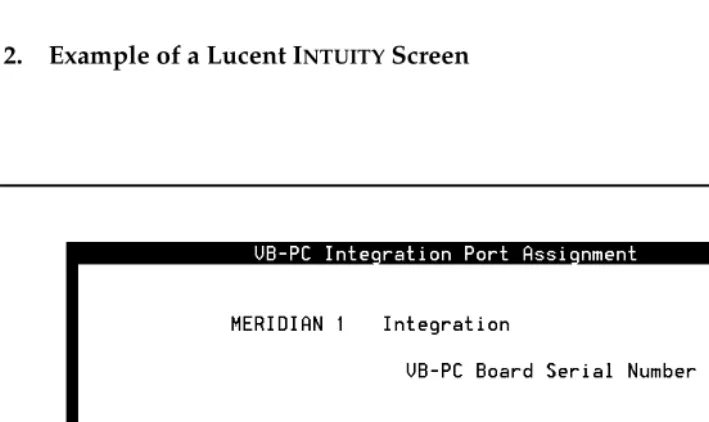
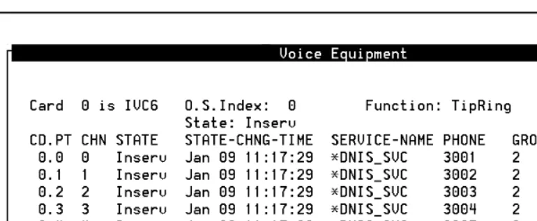
. Menus (Figure 1) present options from which you can choose to view another menu, or a window or screen. Screens request that you enter a command at the enter command: prompt (Figure 2). Windows request and show system information (Figure 4 and Figure 3).ENTER ENTER
ENTER
About This Book
Page xii Conventions Used in This Book
Figure 2. Example of a Lucent INTUITY Screen
About This Book
Page xiii Conventions Used in This Book
Figure 4. Example of a Lucent INTUITY Window Showing Information
Keyboard and Telephone Keypad
Representations
■ Keys that you press on your terminal or PC keyboard are represented as rounded boxes. For example, an instruction to press the Enter key is shown as
Press .
■ Two keys that you press at the same time on your terminal or PC keyboard (that is, you hold down the first key while pressing the second key) are represented as a series inside a rounded box. For example, an instruction to press and hold while typing the letter “d” is shown as
Press .
■ A combination keystroke is a series of keystrokes that combines the two key function described above plus a third key, that is, you press and hold down the first key, then press the second key, then release those keys and press a third key. A combination keystroke is represented as an equation. For example, an instruction to press and hold while typing the letter “d” and then typing the number “1” is shown as
Press +
■ Function keys on your terminal, PC, or system screens (also known as soft keys
)
are represented as rounded boxes followed by the function or value of that key enclosed in parentheses. For example, an instruction to press function key 3 is shown asPress (Choices).
ENTER
ALT
ALT-D
ALT
ALT-D 1
About This Book
Page xiv Conventions Used in This Book
■ Keys that you press on your telephone keypad are represented as square boxes. For example, an instruction to press the first key on your telephone keypad is shown as
Press to record a message.
Screen Displays
■ Values, system messages, field names, and prompts that appear on the screen are shown in typewriter-style Courier type, as shown in the following examples:
— Enter a switch number in the Switch Number field.
— You need to restart the voice System to make these changes active.
■ The sequence of menu options that you must select to display a specific screen or submenu is shown as follows:
Start at the Lucent INTUITY main menu and select
:
In this example, you first access the Switch Interface Administration menu. From that menu you select the Switch Selection window.
■ Windows and screens shown in this book are examples only. The ones you see on your system will be similar, but not exactly the same.
Other Typography
■ Commands and text you type in or enter appear in bold type, as in the following examples:
— Enter change-switch-time-zone at the enter command: prompt. — Enter y in the Remote [Y/N] field.
■ Command variables are shown in
bold italic
type when they are part of what you must type andregular italic
type when they are not, for example:Enter ch ma
machine_name
, wheremachine_name
is the name of the call delivery machine you just created.1
> Switch Selection
About This Book
Page xv Trademarks and Service Marks
Safety and Security Alert Labels
The Lucent INTUITY document set uses the following symbols to call your attention
to potential problems that could cause personal injury, damage to equipment, loss of data, service interruptions, or breaches of toll fraud security:
!
CAUTION:
Indicates the presence of a hazard that if not avoided can or will cause
minor personal injury or property damage, including loss of data.
!
WARNING:
Indicates the presence of a hazard that if not avoided can cause death or
severe personal injury.
!
DANGER:
Indicates the presence of a hazard that if not avoided will cause death or
severe personal injury.
!
SECURITY ALERT:
Indicates the presence of a toll fraud security hazard. Toll fraud is the
unauthorized use of a telecommunications system.
Trademarks and Service Marks
The following trademarked products are mentioned in books in the Lucent INTUITY
document set:
■ 5ESS is a registered trademark of Lucent Technologies. ■ AT is a trademark of Hayes Microcomputer Products, Inc. ■ AUDIX is a registered trademark of Lucent Technologies.
■ cc:Mail is a registered trademark of cc:Mail, a subsidiary of Lotus Development Corporation.
■ COMSPHERE is a registered trademark of Paradyne Corp. ■ CONVERSANT is a registered trademark of Lucent Technologies. ■ DEFINITY is a registered trademark of Lucent Technologies. ■ DMS-100 is a trademark of Northern Telecom Limited. ■ Dterm is a trademark of NEC Telephones, Inc.
About This Book
Page xvi Trademarks and Service Marks
■ Lucent is a trademark of Lucent Technologies. ■ MEGAPORT is a trademark of Equinox Systems, Inc. ■ MEGAPLEX is a trademark of Equinox Systems, Inc. ■ Meridian is a trademark of Northern Telecom Limited.
■ MERLIN LEGEND is a registered tradesman of Lucent Technologies. ■ Microcom Networking Protocol is a registered trademark of Microcom, Inc. ■ Microsoft is a registered trademark of Microsoft Corporation.
■ MS is a registered trademark of Microsoft Corporation. ■ MS-DOS is a registered trademark of Microsoft Corporation. ■ Mitel is a trademark of Mitel Corporation.
■ Motorola is a registered trademark of Motorola, Inc. ■ NEAX is a trademark of NEC Telephone, Inc.
■ NEC is a registered trademark of NEC Telephone, Inc. ■ Netware is a registered trademark of Novell, Inc.
■ Netware Loadable Module is a trademark of Novell, Inc.
■ Northern Telecom is a registered trademark of Northern Telecom Limited. ■ Novell is a registered trademark of Novell, Inc.
■ Paradyne is a registered trademark of AT&T.
■ Phillips is a registered trademark of Phillips Screw Company. ■ Rolm is a registered trademark of International Business Machines. ■ SL-1 is a trademark of Northern Telecom Limited.
■ softFAX is a registered trademark of VOXEM, Inc. ■ SUPERSET is a trademark of Mitel Corporation. ■ SX-100 is a trademark of Mitel Corporation. ■ SX-200 is a trademark of Mitel Corporation. ■ SX-2000 is a trademark of Mitel Corporation.
■ Telephony OneStop is a trademark of Lotus Development Corporation. ■ TMI is a trademark of Texas Micro Systems, Inc.
■ UNIX is a registered trademark of UNIX System Laboratories, Inc. ■ VB-PC is a trademark of Voice Technologies Group, Inc.
■ VoiceBridge is a registered trademark of Voice Technologies Group, Inc. ■ VOXEM is a registered tradesman of VOXEM, Inc.
About This Book
Page xvii Related Resources
Related Resources
This section describes additional documentation and training available for you to learn more about installation of the Lucent INTUITY product.
Documentation
This book is designed to be used in conjunction with the appropriate installation and maintenance books for your platform:
■
I
NTUITYMessaging Solutions Release 4 MAP/40P System Installation
, 585-310-196■
I
NTUITYMessaging Solutions Release 4 MAP/100 System Installation
, 585-310-173■
I
NTUITYMessaging Solutions Release 4 MAP/5P System Installation
, 585-310-185■
I
NTUITYMessaging Solutions Release 4 MAP/40 Maintenance
, 585-310-171■
I
NTUITYMessaging Solutions Release 4 MAP/40P Maintenance
, 585-310-197■
I
NTUITYMessaging Solutions Release 4 MAP/100 Maintenance
, 585-310-174■
I
NTUITYMessaging Solutions Release 4 MAP/5P Maintenance
, 585-310-186The following administration book is also referenced:
■
I
NTUITYMessaging Solutions Release 4 Administration
, 585-310-564See the inside front cover of this book for information on how to order Lucent INTUITY documentation.
Training
Lucent Technologies recommends the following training class as a prerequisite to installing a Lucent INTUITY system:
■ Course No.BTT 506H, INTUITY Messaging Solutions Installation and Maintenance
■ Course No. BTC 102H, INTUITY AUDIX™ System Administration
The following training classes are recommended for account teams who interact with customers integrating a Lucent system with a non-BCS switch:
About This Book
Page xviii How to Comment on This Book
For more information on Lucent INTUITY training, call the BCS Education and Training Center at one of the following numbers:
■ Organizations within Lucent: (904) 636-3261
■ Lucent Technologies customers and all others: (800) 255-8988
Technical Assistance
The following resources are available for technical assistance with Lucent Technologies products and services:
■ Within the United States, for assistance on installation of systems
integrated with a switch via a digital station interface, call 1-800-242-2121, and enter extension 85474.
■ Within Canada, for all systems, call 1-800-242-1234.
■ Within any other country, for all systems, call your local distributor.
How to Comment on This Book
We are interested in your suggestions for improving this book. Please complete and return the comment card (feedback form) located behind the title page.
If the comment card has been removed, send your comments to: Lucent Technologies
Product Documentation Room 22-2H15
11900 North Pecos Street
Denver, Colorado 80234-2703 US
You can also fax your comments to the attention of the Lucent INTUITY writing team at (303) 538-1741. Please mention the name and order number of this book:
I
NTUITY™ Messaging Solutions Release 4 Switch Integration with Digital
Overview of Switch Integration with Digital Station Interface
Page 1-1 Overview
1
1
1
Overview of Switch Integration with
Digital Station Interface
Overview
Integration of the Northern Telecom (Nortel) Meridian 1 and Meridian SL-1 switches with the Lucent™ INTUITY™ system requires that a digital station interface circuit card be installed in the Lucent INTUITY platform. With the digital station interface, these switches can be integrated with the following Lucent INTUITY multi-application platforms (MAPs):
■ MAP/40 ■ MAP/40P ■ MAP/100 ■ MAP/5P
Purpose
This chapter provides background information necessary to integrate a Lucent INTUITY system with a Nortel Meridian 1 or Meridian SL-1 switch using a digital
Overview of Switch Integration with Digital Station Interface
Page 1-2 Method of Integration
1
Method of Integration
Switch integration refers to the sharing of information between a messaging system and a switch to provide a seamless interface to callers and system users. A fully integrated messaging system answers each incoming telephone call with information taken directly from the switch.
Digital Station Interface Circuit Card
To integrate with Meridian 1 and Meridian SL-1 switches, the Lucent INTUITY
system uses as an interface a VoiceBridge-PC (VB-PC) digital station interface circuit card. This circuit card is responsible for interacting with the switch to provide call information and manage message waiting indicator (MWI) updates.
Ports
The digital station interface circuit card has eight ports. Each port emulates a proprietary digital station (telephone set). The emulated digital station forms the key link between the Lucent INTUITY system and the switch for obtaining the call information when the call is forwarded to the Lucent INTUITY system.
Station Emulation
For integration with Meridian 1 and Meridian SL-1 switches, the digital station interface circuit card emulates the Nortel model 2616 digital station. The ports on the digital station interface circuit card can have various keys, such as call appearance keys and other feature keys, configured similarly to the keys on an actual digital station.
The 2616 digital stations have displays that show fields indicating the calling party (CLI) number, the called party (CP) number, and the reason for call redirection, if redirection has taken place. These displays provide the call information necessary for integrating the switch with the Lucent INTUITY system. The application programming interfaces (APIs) that come with the digital station interface circuit card enable the station display to be read.
Hunting
One of the features of the Meridian 1 and Meridian SL-1 switches used to route calls to the INTUITY AUDIX® system is
hunting
. A singlehunt chain
is created that contains extension numbers corresponding to the Tip/Ring lines connected to the Lucent INTUITY system. These extension numbers are mapped, one to one, to the keys of the ports on the digital station interface circuit card. The first Tip/Ring extension number in the hunt chain is assigned as the Lucent INTUITY message retrieval number. The remaining members of the hunt chain are a set ofOverview of Switch Integration with Digital Station Interface
Page 1-3 Method of Integration
1
extension is busy, the switch attempts to connect to the second extension number, and so on until the switch obtains a free extension number in the hunt chain. The switch terminates the call on the first available port. The search for a free extension number in the hunt chain is called
hunting
.Systems with More Than 16 Tip/Ring Lines
A limitation of the hunting feature on the Meridian 1 and Meridian SL-1 switches determines how the Lucent INTUITY system makes use of hunting. These switches allow hunting of only 16 channels, whereas the Lucent INTUITY system platforms can support as many as 64 channels, with one channel mapped to each Tip/Ring line.
For systems with more than 16 Tip/Ring lines, the lines are divided into groups, with each group containing 15 (or fewer) members. Each group is associated on the switch with an automatic call distribution directory number (ACD DN). Hunting among the groups is accomplished by use of a linking ACD DN in the hunt chain.
Primary and Bridged Call Appearances
The method of setting up extension numbers for the integrations with Meridian 1 and Meridian SL-1 switches is called
bridging
. The Tip/Ring port appearances are called theprimary call appearances
, while the various keys of the ports on the digital station interface circuit card having the same extension numbers are calledbridged call appearances
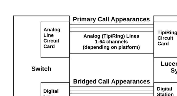
. The switch rings both these appearances when a system user dials a particular extension number.Figure 1-1 illustrates the configuration used to simultaneously ring the primary and bridged call appearances. Each Tip/Ring port on the Lucent INTUITY system is connected to the switch through an analog line as an analog station. Each of the ports on the digital station interface circuit card is connected to the switch as a digital station through a digital line. For every extension of the Lucent INTUITY
Tip/Ring ports a corresponding line appearance key on the emulated digital station on the digital station interface circuit card port is configured.
Overview of Switch Integration with Digital Station Interface
Page 1-4 Method of Integration
1
Figure 1-1. Lucent INTUITY System and Switch Connectivity for Integration
External calls are differentiated from internal calls by the presence of a data string for the CLI. The reason for redirection is decoded from data in another string. Since the Tip/Ring lines on the Lucent INTUITY system are mapped one-to-one to the keys on the port of the digital station interface circuit card, the display information can be mapped to the corresponding Tip/Ring port on which the call lands. The Tip/Ring line channel number is sent to the Lucent INTUITY
system.
Message Waiting Indicator Updates
MWI updates are also performed using the 2616 digital station features. Two keys of the 2616 digital station, called the message indication key (MIK) and the message cancellation key (MCK), are configured on each of the ports of the digital station interface circuit card. By using the MIK or MCK key features, the MWI, (whether it is a light or a stutter tone), is turned on or off, respectively. The driver on the digital station interface circuit card provides information about whether the MWI update was successful.
One port on the digital station interface circuit card (normally, port 8) is dedicated for MWI updates, regardless of how many ports are necessary for Tip/Ring line mapping. A unique extension number is assigned for this port, which need not be contiguous with the extension numbers assigned for the Tip/Ring lines. No hunting is done for MWI updates, and the extension number assigned for MWI updates is not part of the hunt chain.
Analog (Tip/Ring) Lines 1-64 channels (depending on platform)
Switch
Analog Line Circuit Card
Digital Line Circuit Card
Lucent INTUITY
System
Tip/Ring Circuit Card
Digital Station Interface Circuit Card Digital Lines
1-8 ports (as needed)
Overview of Switch Integration with Digital Station Interface
Page 1-5 Demarcation Points
1
Demarcation Points
Lucent service technicians dispatched for Lucent INTUITY system installation cannot make direct connection to or perform administration on switches that are not maintained by Lucent personnel or entities. The demarcation point for systems using the digital station interface circuit card is the end of the Lucent-provided connector cables. See ‘‘Connectivity’’ in Chapter 3, ‘‘Requirements and Administration for Nortel Meridian 1 and Meridian SL-1 Switches’’. Lucent services personnel may, however, connect the
Lucent-supplied cables to the digital station interface circuit card installed in the Lucent INTUITY system.
For additional information concerning the extent of the installation, see the contract between the customer and Lucent Technologies.
Joint Acceptance Testing
Joint acceptance testing is to be executed by both the customer representative and the INTUITY AUDIX® on-site installer when the integration includes Lucent Technologies products and customer-provided equipment. Acceptance testing is performed at the end of an installation to demonstrate to the customer that the integration is operational. The purpose of joint acceptance testing is to have knowledgeable people available to test and resolve issues before final completion of the service order.
Lucent I
NTUITY
Features and
Functionality Supported
Listed below are Lucent INTUITY features and functions supported in integrations with Meridian 1 and Meridian SL-1 switches:
■ Call forward to personal greetings — Internal
— External — Busy — No answer — Out-of-hours
■ Transfers (blind transfers only) — Escape/return to operator (0) — Subscribers
Overview of Switch Integration with Digital Station Interface
Page 1-6 Lucent INTUITY Features and Functionality Unsupported
1
■ Message notification — Outcalling — MWI updates
■ Private networking configuration with multiple switches behind a single Lucent INTUITY system
■ Applications
— INTUITY AUDIX — Lodging
■ INTUITY AUDIX networking
— High-speed digital networking (DCP) — TCP/IP networking
— AMIS analog ■ Fax messaging
Lucent I
NTUITY
Features and
Functionality Unsupported
Hunting of multiple hunt groups is
not
supported. Therefore, configurations cannot be implemented whereby Tip/Ring lines are dedicated for some Lucent INTUITY feature or application, such as the Lucent INTUITY Lodging application or an automated attendant.Integration Performance
■ The average MWI update time is approximately 5 seconds. The time may increase under heavy switch load and if the Lucent INTUITY system has a number of invalid subscriber mailboxes.
■ The average call answer delay is approximately one ring. The delay may increase under heavy traffic on the switch or the Lucent INTUITY system. The delay may also increase if QPC578 digital line circuit cards are used on the switch (Meridian SL-1 switch only). See ‘‘Switch Hardware
Requirements’’in Chapter 3, ‘‘Requirements and Administration for Nortel Meridian 1 and Meridian SL-1 Switches’’.
■ MWI updates to members in an automatic call distribution (ACD) group are not supported when a message is delivered to an automatic call distribution directory number (ACD DN). Therefore, in systems where shared mailboxes are used, MWI updates cannot be performed on the various stations that access the shared mailbox.
Overview of Switch Integration with Digital Station Interface
Page 1-7 General Configuration Requirements
1
■ Automated attendant setup for call routing to external locations takes longer for completing the call and may require additional switch setup. ■ A small percentage of calls may be answered in an unintegrated mode during a very heavy traffic condition. If QPC578 digital line circuit cards are used on the switch (Meridian SL-1 switch only), performance may degrade further. The NT8D02 digital line circuit card performs better than the QPC578 card. See ‘‘Switch Hardware Requirements’’in Chapter 3, ‘‘Requirements and Administration for Nortel Meridian 1 and Meridian SL-1 Switches’’.)
■ Disconnects are slower and less reliable for systems with switch software Release 15 and Release 16 than with Release 17 and greater because the switch does not provide disconnect supervision with the earlier releases. See ‘‘Switch Software Requirements’’ in Chapter 3, ‘‘Requirements and Administration for Nortel Meridian 1 and Meridian SL-1 Switches’’.
General Configuration Requirements
■ Contiguous extension numbers are assigned to the Tip/Ring ports of the Lucent INTUITY system from the second tip/ring port onwards.
■ The voice ports are divided equally among the ports on the digital station interface circuit card used for integration.
■ As a general rule, no more than nine voice ports should be mapped to a port on the digital station interface circuit card.
■ If MWI updates are to be performed on the system, a port on the digital station interface circuit card must be dedicated to this function.
■ The digital lines that are to connect to the ports on the digital station interface circuit cards in the Lucent INTUITY system must be from different digital line circuit cards on the Meridian switch, preferably from digital line circuit cards in slot 0 or slot 1. This arrangement distributes the traffic across the digital line circuit cards and gives high priority for the ports.
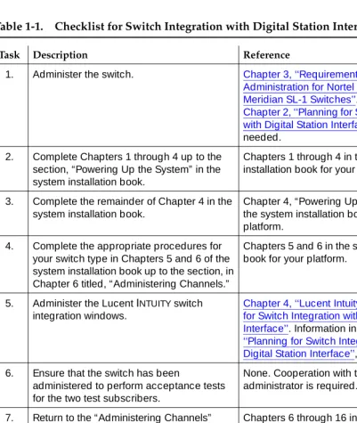
Checklist for Switch Integration
The following checklist (Table 1-1) outlines sequentially the process of integrating the Lucent INTUITY system with a Meridian 1 or Meridian SL-1 switch. It is
assumed that you are performing the integration as part of installation of the Lucent INTUITY system and completing the procedures specified in the system installation book for your platform.
Overview of Switch Integration with Digital Station Interface
Page 1-8 Checklist for Switch Integration
1
If you need to install the software, see Chapter 9 (for MAP/5P) or Chapter 8 (for all other platforms), “Installing the Switch Integration Software Packages,” in the maintenance book for your platform.
Table 1-1. Checklist for Switch Integration with Digital Station Interface
Task Description Reference
1. Administer the switch. Chapter 3, ‘‘Requirements and
Administration for Nortel Meridian 1 and Meridian SL-1 Switches’’. Information in
Chapter 2, ‘‘Planning for Switch Integration with Digital Station Interface’’, is also needed.
2. Complete Chapters 1 through 4 up to the section, “Powering Up the System” in the system installation book.
Chapters 1 through 4 in the system installation book for your platform.
3. Complete the remainder of Chapter 4 in the system installation book.
Chapter 4, “Powering Up the System” in the system installation book for your platform.
4. Complete the appropriate procedures for your switch type in Chapters 5 and 6 of the system installation book up to the section, in Chapter 6 titled, “Administering Channels.”
Chapters 5 and 6 in the system installation book for your platform.
5. Administer the Lucent INTUITY switch integration windows.
Chapter 4, ‘‘Lucent Intuity Administration for Switch Integration with Digital Station Interface’’. Information in Chapter 2, ‘‘Planning for Switch Integration with Digital Station Interface’’, is also needed. 6. Ensure that the switch has been
administered to perform acceptance tests for the two test subscribers.
None. Cooperation with the switch administrator is required.
7. Return to the “Administering Channels” section in Chapter 6 of the system
installation book and complete all required tasks through Chapter 16.
Chapters 6 through 16 in the system installation book for your platform.
8. Validate and, if necessary, troubleshoot the integration.
Chapter 5, ‘‘Integration Validation and Troubleshooting’’.
9. Cut to service by notifying the switch administrator or your project manager to change the system users’ call forwarding coverage path to the Lucent INTUITY
system.
None.
Planning for Switch Integration with Digital Station Interface
Page 2-1 Overview
2
2
2
Planning for Switch Integration with
Digital Station Interface
Overview
This chapter describes the information that must be obtained in advance of performing the procedures to integrate a Northern Telecom (Nortel) Meridian 1 or Meridian SL-1 switch with the Lucent™ INTUITY™ system. Worksheets are included to record the necessary information. Completion of the worksheets:
■ Ensures that both the switch and the Lucent INTUITY system are properly administered.
■ Aids cooperation between the personnel installing the Lucent INTUITY
system and the switch administrator.
Responsibility for implementing the information on the worksheets is as follows: ■ The project planner or project manager is responsible for completing the
worksheets.
■ The switch administrator must provide information on the worksheets specific to the switch. The switch administrator is also responsible for administering the information on the switch.
■ The Lucent installer is responsible for administering information on the worksheets specific to the Lucent INTUITY system.
Purpose
This chapter provides worksheets (Table 2-2 through Table 2-10) used by planners or project managers, Lucent installers, and the switch administrator to integrate a Lucent INTUITY system with a Nortel Meridian 1 or Meridian SL-1
Planning for Switch Integration with Digital Station Interface
Page 2-2 Checklist for Planning
2
Checklist for Planning
The following checklist (Table 2-1) lists the worksheets that must be completed before the integration. Use the checklist to ensure that all worksheets are completed.
Table 2-1. Planning Checklist
Worksheet Section
Table 2-2 ‘‘Determining the Number of Ports to Use on the Digital Station Interface Circuit Card’’
Table 2-3 ‘‘Obtaining Terminal Numbers for Ports on the Digital Station Interface Circuit Card’’
Table 2-4 ‘‘Obtaining the Lucent Intuity Message Retrieval Number’’
Table 2-5 ‘‘Obtaining the Dedicated MWI Port Extension Number (Optional)’’
Table 2-6 ‘‘Obtaining Extension Numbers and ACD DNs for the Lucent Intuity Tip/Ring Lines’’
Table 2-7 ‘‘Mapping Tip/Ring Extensions to Keys on the Digital Station Interface Circuit Card Ports’’
Table 2-9 ‘‘Determining the Call Redirection Display Strings Currently Set on the Switch’’
Table 2-10 ‘‘Determining the Serial Number of the Digital Station Interface Circuit Card’’
Table 2-11 ‘‘Determining the Start and End Times for Night Audits (If Run)’’
NOTE:
This worksheet is required only for integrations with Meridian 1 and SL-1 switches when night audits are run.
Table 2-12 ‘‘Obtaining the Day/Night Service Automated Attendant Number (If Used)’’
NOTE:
This worksheet is required only for integrations with Meridian 1 and Meridian SL-1 switches when the customer has day/night service and uses the automated attendant feature of the INTUITY AUDIX system.
Table 2-13 ‘‘Obtaining the Express Messaging Automated Attendant Number (If Used)’’
NOTE:
This worksheet is required only for integrations with Meridian 1 and Meridian SL-1 switches that will use the Lucent INTUITY Express Messaging feature.
Table 2-14 ‘‘Obtaining the Call Routing Automated Attendant Number (If Used)’’
Table 2-15 ‘‘Obtaining Numbers for the Call Routing Automated Attendant Menu (If Used)’’
Table 2-16 ‘‘Planning for Phantom Numbers (If Used)’’
Planning for Switch Integration with Digital Station Interface
Page 2-3 Determining the Number of Ports to Use on the Digital Station Interface Circuit
2
Determining the Number of Ports
to Use on the Digital Station Interface
Circuit Card
Table 2-2 provides guidelines for determining the number of ports to use on the digital station interface circuit card based on the number of extension numbers required on the Lucent INTUITY system.
■ As a general rule, for satisfactory performance, a maximum of nine extension numbers on the Lucent INTUITY system can be mapped to a single port on the digital station interface circuit card. See ‘‘Mapping Tip/Ring Extensions to Keys on the Digital Station Interface Circuit Card Ports’’ below for information for more information on the distribution of Tip/Ring lines across the ports.
■ Operating efficiency can be enhanced by distributing the extension numbers for the Tip/Ring channels across a greater number of ports. ■ If MWI updates are to be performed on the system,
one port
on the digitalstation interface circuit card must be reserved
exclusively
for this purpose. By convention, port 8 is used for MWI updates. If MWI updates are not to be performed, then extension numbers can be mapped to all eight ports on the digital station interface circuit card.Worksheet
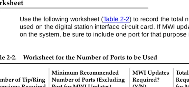
Use the following worksheet (Table 2-2) to record the total number of ports to be used on the digital station interface circuit card. If MWI updates are to be done on the system, be sure to include one port for that purpose in the total.
Table 2-2. Worksheet for the Number of Ports to be Used
Number of Tip/Ring Extensions Required
Minimum Recommended Number of Ports (Excluding Port for MWI Updates)
MWI Updates Required? (Y/N)
Total Number of Ports Required (Including Port for MWI Updates
5 or fewer 1
6-10 2
11-18 3
19-24 4
25-30 5
31-40 6
Planning for Switch Integration with Digital Station Interface
Page 2-4 Obtaining Terminal Numbers for Ports on the Digital Station Interface Circuit Card
2
Examples
■ For a system with 18 voice channels, 3 ports (minimum) on the digital station interface circuit card are recommended. If MWI updates are to be performed on the system, 4 ports (minimum) are required.
■ For a system with the maximum of 64 voice channels, 7 ports on the digital station interface circuit card are recommended. If MWI updates are to be performed on the system, 8 ports are required.
Obtaining Terminal Numbers for Ports
on the Digital Station Interface Circuit
Card
Every termination on the Meridian 1 or Meridian SL-1 switch is uniquely identified by a
terminal number
(TN). The switch TN is a 4-digit number, for example 4 0 4 0, that identifies the physical location on the switch digital line card of a line to or from the switch. The digits designate, from left to right, the following:NOTE:
Do not confuse the abbreviation “TN” used for a terminal number on the switch with the abbreviation “TN” used in Lucent circuit pack designations.
Load Leveling
For load leveling, every port of the digital station interface circuit card on the Lucent INTUITY system should be assigned to a different digital line card on the switch. That is, only one port should be assigned to a particular switch digital line card.
On Meridian 1 and Meridian SL-1 switches, the digital line cards in slot 0 and slot 1 are given higher priority than the cards in other slots. Therefore, for optimal system performance, all ports should be assigned to digital line cards in these slots.
Worksheet
Use the following worksheet (Table 2-3) to record the TNs for the ports on the digital station interface circuit card that will be used for switch integration. Use the following procedure to fill in the worksheet:
Loop number The loop to which the termination belongs.
Planning for Switch Integration with Digital Station Interface
Page 2-5 Obtaining the Lucent INTUITY Message Retrieval Number
2
1. Obtain from the switch administrator a switch TN for
each
port on the digital station interface circuit card that will be used for integration or MWI updates.■ Make sure each TN is from a different digital line card on the switch. ■ Assign only one port to a digital line card.
■ Assign the ports to digital line cards in slot 0 or slot 1.
NOTE:
A TN is not required for any ports that will not be used for integration. By convention, port 8 is used for MWI updates.
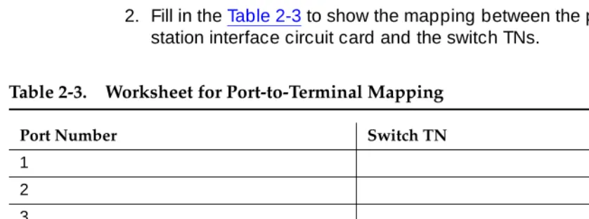
2. Fill in the Table 2-3 to show the mapping between the ports on the digital station interface circuit card and the switch TNs.
Obtaining the Lucent I
NTUITY
Message
Retrieval Number
The Lucent INTUITY number is the extension number that system users call to
retrieve their messages. This number is the first Tip/Ring extension in the hunt chain mapped to the keys on the digital station interface circuit card ports. See ‘‘Mapping Tip/Ring Extensions to Keys on the Digital Station Interface Circuit Card Ports’’ below for related information.
The extension number assigned as the Lucent INTUITY number does
not
need tobe contiguous with the extension numbers used for mapping the remaining Tip/Ring lines. (It may be contiguous, however.) See ‘‘Obtaining Extension Table 2-3. Worksheet for Port-to-Terminal Mapping
Port Number Switch TN
1 2 3 4 5 6 7 8
Planning for Switch Integration with Digital Station Interface
Page 2-6 Obtaining the Dedicated MWI Port Extension Number (Optional)
2
Worksheet
Use the following worksheet (Table 2-4) to record the Lucent INTUITY message
retrieval number.
Obtaining the Dedicated MWI Port
Extension Number (Optional)
If MWI updates are to be performed on the system, obtain from the switch administrator a unique number not assigned to any other extension on the switch.
The extension number assigned for MWI updates does
not
need to becontiguous with the extension numbers used for the remaining Tip/Ring lines. (It may be contiguous, however.) See ‘‘Obtaining Extension Numbers and ACD DNs for the Lucent Intuity Tip/Ring Lines’’ below for related information.
Worksheet
Use the following worksheet (Table 2-5) to record the MWI port extension number.
Obtaining Extension Numbers and
ACD DNs for the Lucent I
NTUITY
Tip/Ring Lines
Integration with a Meridian 1 or Meridian SL-1 switch requires
contiguous
extension numbers for the Tip/Ring lines on the Lucent INTUITY system. An extension number is required for every Tip/Ring line on the system.
Table 2-4. Worksheet for the Lucent INTUITY Message Retrieval Number
Lucent INTUITY number:
Continued on next page
Table 2-5. Worksheet for the MWI Port Extension Number
MWI port extension number:
Planning for Switch Integration with Digital Station Interface
Page 2-7 Obtaining Extension Numbers and ACD DNs for the Lucent INTUITY Tip/Ring Lines
2
NOTE:
The
first
extension number is assigned as the Lucent INTUITY message retrieval number and is configured separately (see Table 2-4). Theextension number for MWI updates is also configured separately (see Table 2-5). These two extension numbers do not needs to be contiguous with each other or the remaining Tip/Ring lines. All other Tip/Ring extension numbers on the system
must
be contiguous.For example, if 30 Tip/Ring lines are needed, any of the following sets of 29 contiguous extensions could be used, depending on the number of digits in the dial plan (extension length).
2001-2029, 000-028, 65550-65578
These ranges do
not
include the Lucent Intuity message retrieval number or the MWI port extension number.For systems with more than 16 Tip/Ring extension numbers, the switch
administrator must provide unique automatic call distribution directory numbers (ACD DNs) for each group of 15 extension numbers from 16 upwards:
■ ACD DN 1 is used for Tip/Ring extensions 16-30. ■ ACD DN 2 is used for Tip/Ring extensions 31-45. ■ ACD DN 3 is used for Tip/Ring extensions 46-60. ■ ACD DN 4 is used for Tip/Ring extensions 61-64.
Worksheet
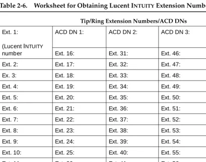
Use the following worksheet (Table 2-6) to configure the extension numbers and ACD DNs. To fill in the worksheet, do the following:
1. Obtain an appropriate set of contiguous extension numbers from the switch administrator.
2. Obtain an appropriate set of ACD DNs from the switch administrator, if required (systems with more than 16 Tip/Ring extension numbers). 3. In Table 2-6, record the Lucent INTUITY message retrieval number as the
first extension number (Ext. 1).
See Table 2-4 for the Lucent INTUITY message retrieval number.
4. Beginning with Ext. 2 in the table and proceeding
in order
, record all the extension numbers, from lowest to highest.5. Record the ACD DNs, if required.
NOTE:
Planning for Switch Integration with Digital Station Interface
Page 2-8 Mapping Tip/Ring Extensions to Keys on the Digital Station Interface Circuit Card
2
Tip/
Mapping Tip/Ring Extensions to Keys
on the Digital Station Interface Circuit
Card Ports
The Tip/Ring lines on the Lucent INTUITY system must be mapped correctly to the keys and ports on the digital station interface circuit card.
■ For best system performance, distribute the Tip/Ring lines as equally as possible across the recommended number of ports. (See Table 2-2 for the recommended number of ports.)
■ If the lines cannot be distributed exactly equally, map the larger number of lines to the lowest-numbered ports.
Table 2-6. Worksheet for Obtaining Lucent INTUITY Extension Numbers
Tip/Ring Extension Numbers/ACD DNs
Ext. 1:
(Lucent INTUITY
number
ACD DN 1: ACD DN 2: ACD DN 3: ACD DN 4:
Ext. 16: Ext. 31: Ext. 46: Ext. 61: Ext. 2: Ext. 17: Ext. 32: Ext. 47: Ext. 62:
Ex. 3: Ext. 18: Ext. 33: Ext. 48: Ext. 63 Ext. 4: Ext. 19: Ext. 34: Ext. 49: Ext. 64:
Ext. 5: Ext. 20: Ext. 35: Ext. 50: Not used. Ext. 6: Ext. 21: Ext. 36: Ext. 51:
Ext. 7: Ext. 22: Ext. 37: Ext. 52: Ext. 8: Ext. 23: Ext. 38: Ext. 53:
Ext. 9: Ext. 24: Ext. 39: Ext. 54: Ext. 10: Ext. 25: Ext. 40: Ext. 55:
Ext. 11: Ext. 26: Ext. 41: Ext. 56: Ext. 12: Ext. 27: Ext. 42: Ext. 57:
Ext. 13: Ext. 28: Ext. 43: Ext. 58: Ext. 14: Ext. 29: Ext. 44: Ext. 59:
Ext. 15: Ext. 30: Ext. 45: Ext. 60:
Planning for Switch Integration with Digital Station Interface
Page 2-9 Mapping Tip/Ring Extensions to Keys on the Digital Station Interface Circuit Card
2
For example, excluding the dedicated port for MWI updates, for systems with 24 Tip/Ring lines a minimum of 4 ports is recommended (Table 2-2). The optimal distribution of the lines across the ports is 6-6-6-6. If for enhanced system performance the 24 lines are to be mapped onto 5 ports, the optimal distribution is 5-5-5-5-4. For 6 ports, the distribution is 4-4-4-4-4-4. For 7 ports, the
distribution is 4-4-4-3-3-3-3.
As another example, excluding the dedicated port for MWI updates, a minimum of 7 ports is recommended for systems with 64 Tip/Ring lines. The optimal distribution of the lines across the ports is 10-9-9-9-9-9-9. If MWI updates are not to be performed on the system, then all 8 ports are available for Tip/Ring
mapping, and the optimal distribution is 8-8-8-8-8-8-8-8.
Worksheet
Use the following worksheet (Table 2-7) to map the Lucent INTUITY system
Tip/Ring lines to the keys of the digital station interface circuit card ports. The lines must be mapped in sequential order
across
the ports. To fill in the worksheet, do the following:1. Record the switch TNs obtained for the ports on the digital station interface circuit card in the fields at the top of the worksheet. See Table 2-3 for the switch TNs.
2. If the system is to perform MWI updates, fill in the key 0 scr entry for port 8 with the extension number recorded in Table 2-5.
NOTE:
By convention, port 8 is used for MWI updates. Another port can be used, however.
3. Starting with the first Tip/Ring extension number on the Lucent INTUITY
system (see Table 2-6) and preceding
sequentially
, fill in the fields in the tablehorizontally
, one-by-one, starting with the field for the key 0 scr. Observe the following guidelines:■ If any port is not used, leave its corresponding column blank. ■ If the system has a port dedicated for MWI updates do not map any
Tip/Ring numbers to that port. The extension number you entered in Step2should be the only entry for the port.
Planning for Switch Integration with Digital Station Interface
Page 2-10 Mapping Tip/Ring Extensions to Keys on the Digital Station Interface Circuit Card
2
NOTE:
The worksheet contains no Key 7. The switch reserves Key 7.
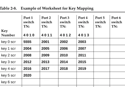
Example
The following example (Table 2-8) shows entries for a system with 21 Tip/Ring lines where MWI updates are to be performed:
■ Ports 1 through 4 are used for call integration, and port 8 is dedicated for MWI updates. The switch TNs for these ports are, respectively, 4 0 1 0, 4 0 1 1, 4 0 1 2, 4 0 1 3, and 4 0 1 4.
■ The Lucent INTUITY message retrieval number is 5555, and therefore 5555 is used as the extension number for the first Tip/Ring line (key 0 scr, port 1).
■ For Tip/Ring lines 2 through 21, contiguous extension numbers 2001 through 2020 are used. These numbers are mapped sequentially across ports 1 through 4.
■ The extension number assigned for MWI updates is 5999, and it is recorded under port 8.
■ The distribution of Tip/Ring lines to ports is 6-5-5-5. Table 2-7. Worksheet for Key Mapping
Key Number Port 1 switch TN: Port 2 switch TN: Port 3 switch TN: Port 4 switch TN: Port 5 switch TN: Port 6 switch TN: Port 7 switch TN: Port 8 switch TN:
key 0 scr key 1 scr
key 2 scr key 3 scr
key 4 scr key 5 scr
key 6 scr key 8 scr
key 9 scr key 10 scr
key 11 scr
Planning for Switch Integration with Digital Station Interface
Page 2-11 Determining the Call Redirection Display Strings Currently Set on the Switch
2
Determining the Call Redirection
Display Strings Currently Set on the
Switch
The Lucent INTUITY system uses call redirection display strings sent by the switch
to parse call data. The settings for these strings on the switch and on the Lucent INTUITY system must match for the integration to succeed.
The switch administrator can check the call redirection display strings currently set on the switch by using overlay 95 and entering the following commands at the switch administration terminal:
LD95 REQ PRT TYPE CPND CUST 0
Among other details, the output of these commands shows the call redirection
Table 2-8. Example of Worksheet for Key Mapping
Key Number
Port 1 switch TN:
4 0 1 0
Port 2 switch TN:
4 0 1 1
Port 3 switch TN:
4 0 1 2
Port 4 switch TN:
4 0 1 3
Port 5 switch TN: Port 6 switch TN: Port 7 switch TN: Port 8 switch TN:
4 0 1 4
key 0 scr 5555 2001 2002 2003 5999
key 1 scr 2004 2005 2006 2007
key 2 scr 2008 2009 2010 2011
key 3 scr 2012 2013 2014 2015
key 4 scr 2016 2017 2018 2019
key 5 scr 2020
key 6 scr
key 8 scr key 9 scr
key 10 scr key 11 scr
Planning for Switch Integration with Digital Station Interface
Page 2-12 Determining the Serial Number of the Digital Station Interface Circuit Card
2
CFNA: <
call_forward_on_no_answer
> HUNT: <call_forward_on_busy
> CFWD: <cover_all_calls
>where:
■ <
call_forward_on_no_answer
> is the string to forward answered calls to the Lucent INTUITY system.■ <
call_forward_on_busy
> is the string to forward busy calls to the Lucent INTUITY system.■ <
cover_all_calls
> is the string for call forward all calls to the Lucent INTUITYsystem.
Worksheet
Use the following worksheet (Table 2-9) to record the current switch settings for the call redirection display strings.
NOTE:
If the output of the overlay 95 commands above does
not
list the call redirection display strings, then leave Table 2-9 blank. Ensure that the switch administrator configures the strings as described in ‘‘Configuring the Call Redirection Display Strings’’ in Chapter 3, ‘‘Requirements andAdministration for Nortel Meridian 1 and Meridian SL-1 Switches’’. See also ‘‘Setting the Call Redirection Display Strings’’ in Chapter 4, ‘‘Lucent Intuity Administration for Switch Integration with Digital Station Interface’’.
Determining the Serial Number of the
Digital Station Interface Circuit Card
The serial number of the VB-PC digital station interface circuit card is a 4-digit number needed for Lucent INTUITY administration. This number is printed on a stamp affixed to the card faceplate, where it is easily visible. It also appears on the surface of the circuit card. For an illustration of the circuit card showing the
Table 2-9. Worksheet for Switch Call Redirection Display String Settings
Reason String Configured on the Switch
Call forward on no answer Call forward on busy
Cover all calls
Planning for Switch Integration with Digital Station Interface
Page 2-13 Determining the Start and End Times for Night Audits (If Run)
2
locations of the serial number, see Chapter 5, “Replacing or Installing Circuit Cards” in the maintenance for your platform. The serial number may be prefixed by characters indicating the switch type. You must strip off these characters to get the 4-digit serial number. For example, a card for the Meridian 1 switch might be labeled M1 3093. Strip off the prefix (M1) to get the serial number: 3093
Worksheet
Use the following worksheet (Table 2-10) to record the serial number of the digital station interface circuit card.
Determining the Start and End Times
for Night Audits (If Run)
The Meridian 1 and Meridian SL-1 switches normally perform an audit every 24 hours. Since the audit is usually done at night, it is called the night audit or midnight audit. Any MWI activity that occurs while the audit runs can create a conflict that disables the affected digital station interface port. If all ports go out of service, no calls can be integrated and switch personnel must return the ports to service. Therefore, MWI updates
must
be blocked while the switch audit runs.Worksheet
Use the following worksheet (Table 2-11) to record the times when audits normally start and end. Use the 24-hour format
HH MM SS
, where:■
HH
is the hour in the 24-hour system (range 0-23). ■MM
is the minute (range 0-59).■
SS
is the second (range 0-59).Table 2-10. Worksheet for the Digital Station Interface Circuit Card Serial Number
Serial number:
Continued on next page
Table 2-11. Worksheet for the for the Night Audits Start and Stop Times
Start time for night audits: (24-hour format)
Planning for Switch Integration with Digital Station Interface
Page 2-14 Obtaining the Day/Night Service Automated Attendant Number (If Used)
2
Obtaining the Day/Night Service
Automated Attendant Number (If
Used)
NOTE:
This worksheet is required only for Meridian 1 and Meridian SL-1 integrations when the customer has day/night service.
The day/night service number is an INTUITY AUDIX extension number administered as an automated attendant mailbox.
Worksheet
Use the following worksheet (Table 2-12) to record the automated attendant number used for day/night service.
Obtaining the Express Messaging
Automated Attendant Number (If
Used)
NOTE:
This worksheet is required only for Meridian 1 and Meridian SL-1 integrations when the customer uses the Lucent INTUITY Express Messaging feature.
The Lucent INTUITY Express Messaging number is an INTUITY AUDIX extension number administered as an automated attendant that a system user dials to use the Express Messaging feature. See Appendix A, ‘‘Administering Express Messaging’’ for a description of this feature. See also ‘‘Planning for Phantom Numbers (If Used)’’ below for information on administration required for phantom numbers.
Table 2-12. Worksheet for the Day/Night Service Automated Attendant Number
Day/night service number:
Planning for Switch Integration with Digital Station Interface
Page 2-15 Obtaining the Call Routing Automated Attendant Number (If Used)
2
Worksheet
Use the following worksheet (Table 2-13) to record the Express Messaging number.
Obtaining the Call Routing Automated
Attendant Number (If Used)
NOTE:
This worksheet is required only for Meridian 1 and Meridian SL-1
integrations when the customer uses an automated attendant number for call routing to far-end switches in the customer network.
A call routing number is an INTUITY AUDIX extension number configured as an automated attendant that a system user dials to access far-end switches in a customer network. See Appendix B, ‘‘Administering Call Routing for Far-End Switches’’ for a description of this feature and ‘‘Obtaining Numbers for the Call Routing Automated Attendant Menu (If Used)’’ below for additional planning that must be done for this feature. See also ‘‘Planning for Phantom Numbers (If Used)’’ below for information on administrative requirements for phantom numbers.
Worksheet
Use the following worksheet (Table 2-13) to record the automated attendant number for call routing to far-end switches.
Table 2-13. Worksheet for the Express Messaging Automated Attendant Number
Express Messaging number:
Continued on next page
Table 2-14. Worksheet for the Call Routing Automated Attendant Number
Call routing number:
Planning for Switch Integration with Digital Station Interface
Page 2-16 Obtaining Numbers for the Call Routing Automated Attendant M