18th International Conference on Structural Mechanics in Reactor Technology (SMiRT 18) Beijing, China, August 7-12, 2005 SMiRT18-O04-1
A PREDICTION METHOD OF WEAR DEPTH CONSIDERING THE
GAP BETWEEN TUBE AND SUPPORT IN STEAM GENERATOR
Chi Yong PARK
Nuclear Power Research Lab., KEPRI
Phone: +82-42-865-5656,
Fax: +82-42-865-5604
E-mail: [email protected]
Yong Sun LEE
Nuclear Power Research Lab., KEPRI
Phone: +82-42-865-5654,
Fax: +82-42-865-5604
E-mail: [email protected]
Tae Ryong KIM
Nuclear Power Research Lab., KEPRI in KOREA
Phone: +82-42-865-5640,
Fax: +82-42-865-5604
E-mail: [email protected]
ABSTRACT
When the tube contacts to support plate or anti-vibration bar in steam generator of the nuclear power plants, the contact area is worn out by their relative displacement and contact force. The major flow-induced vibration mechanisms such as fluid-elastic and turbulence excitation can cause the various types of tube wear. It is generally accepted that the tube wear due to vibration is affected by the presence of gap clearance between tube and support plate. Connors showed that the wear depth of tube could be estimated by using the relationship between wear volume and sliding distance for contact time. Au-Yang predicted the wear depth by using the nonlinear characteristics of normal work rate to contact time. In this study, a method for prediction of tube wear including gap between tube and its support has been proposed. A proposed method was derived from previous methodologies for obtaining the wear depth of tubes. The effect of gap size on the steam generator tubes wear is also analyzed and estimated by the proposed methods which include the relations of wear depth versus normal work rate and wear depth. It was investigated that normal work rates is decreased as the gap is increased, and normal work rates are decreased as operating time is increased. Thus, I was conclude gap effect is decreased as operating time is increased. When the normal work rate is less than 10 mw using wear coefficients with generally accepted level, the effect of gap size on the normal work rate is negligibly small. A proposed method may be applicable to the evaluation of gap effects under the fluid conditions of turbulence excitation in design and maintenance of the nuclear power plant.
Keywords: Steam Generator, Tube & Support, Gap, Wear Depth
1. INTRODUCTION
In steam generator of nuclear power plants, flow-induced vibration(FIV) can occur by two phase flow in secondary region of steam generator(SG). Flow induced vibration causes tube wear due to relative displacement and contact force between tube and its supports. The major flow-induced vibration mechanisms such as fluid-elastic and turbulence excitation can cause the various types of tube. It is generally accepted that tube wear by vibration of tube and support is affected by the presence of gap between tube and support plate.
turbulence excitation require the long time for occurring tube wear. Therefore effects of those mechanisms have to be assessed in case of estimating the wear depth with considering the gap effects.
It is well known as previously mentioned that tube wear takes place due to flow induced vibration between tube and its support in the steam generator and there are many available study results about tube wear and flow induced vibration. However the literatures considering the tube wear with the clearance between the tube and support plate are not many at the author's best knowledge.
The wear volume was deduced from terms of the cross sectional area, in which consider the gap size. However study of gap effects was not carried out(Conners). A relation of normal work rate and gap was analyzed by the model of non-linear flow induced vibration(Axisa). This work has been reported that when turbulence excited external force is applied to the tube system, the wear rate would decrease as the tube to support clearance increase. On the other hand, if the tube is fluid elastically unstable, then the wear rate would increase with gap clearance.
Au-Yang considered that the tube-support plate clearance increases as the tube wall wears out, and since non-linear tube dynamics is a function of the gap, the normal work rate changes with time as the tube wall wears out. From this concept, he obtained the relation of worn depth and normal work rate at given gap distance between the tube and support plate by using of work rate found by Breneman and Gurdal. Nevertheless the smart investigation of gap effects of SG tubes, various gap sizes were not considered and a characteristic constant was not calculated in there. The FIV mechanism affecting on tube wear was investigated from the various wear experimental data and applicability of estimation methodology for gap effect was concerned.
In this study, a method for evaluating gap effects in tube and its support was derived independently and implemented to a tube of steam generator in Korean Standard Nuclear Power(KSNP) plant by this work. Relation for calculating the wear volume was expressed in terms of wear coefficient, normal force, displacement and contact time. The effect of gap on the wear volume or wear depth was evaluated with respect to various gap sizes. Addition to this, Au-Yang method for estimating gap effects was reviewed carefully, and implemented independently and compared with the present study. The wear depth percentage could be obtained by the relation of normal work rate and gap with respect to various gap sizes.
2. TUBE WEAR CAUSED BY GAP BETWEEN THE TUBE AND SUPPORT
2.1 Wear volume by relation of worn shape and gap
Connors presented the paper related to the fretting wear of steam generator due to the flow induced vibration. Connors was derived the wear volume in terms of the cross sectional area, in which he expressed by subtended distance, gap size, outside of tube and inside of support radii. And the wear volume was obtained by integration of a derived relation on contact zone of tube and its support. He is assumed the value of worn depth. For deriving the second relation, he also expressed the worn volume in terms of wear coefficient, normal force and tangential distance expressed by contact time. Finally he could calculate the time, t combining above two equations.
In order to investigate the effect of gap between tube and its support in wear estimation, a method of calculating the wear volume by Connors was adapted firstly. It is the purpose of this study that the tube wear caused by the gap size in steam generator is investigated. In order to this objective, it is assumed that the tube and its support maintain its original configuration geometrically during wearing tube, and the wear of tube is occurred equally on surface of each half of the support plate thickness. This implies that tube is initially unlocked in the hole and that the mode shape gives a constant slope of the tube through the baffle plate. Under this assumption, the area of worn tube was derived as followings;
s
R x s s
R
x x R x xR x h C x R
R
Area 2sin 1 ( 2 2) ( 2 2)2 2( ) 2sin 1
1 2
1 −
− + − − − + + −
= (1)
Where h is the maximum wear depth, R, Rs is the radii of outside tube and inside of the support respectively,
C is the gap between R and Rs. As tube wear occurred, geometrical description for wear segment is shown in
Fig.1 Formed wear segment shape in tube and support Fig.2 Progression of SG tube wear
A intersecting point x between tube outer radii and inner radii of its support is expressed following Eq.(2)
2 1
2 2 2 2 2
] [ s2 {R 4R(h(Ch)C)}
s R
x= − − −+ + (2)
As tube wear progress, geometrical description for wear segment to the axial direction of tube is shown in Fig.2. Tube wear occur initially at the edge area of support hole as shown an area I section of Fig. 1. As tube wear progress, the worn area will be extended to area II and III in Fig. 2 and the wear depth will be larger. Therefore the x value changes in the direction of the support plate thickness as easily known in Fig.1, and this will be pyramid scar initially and the frustum of pyramid. Finally it will be a cylinder.
When 1 2 1
0
L
h ≤θ , the initial wear volume, V is A1h1/3θ0 where L1 is the support plate length, θ0is the relative
inclination to the support plate, y0 is the amplitude and L is the length of tube, and L can be calculated when the
first frequency, fn , is known assuming both ends are simply supported and fixed beam.
If h1 is more larger than θ0(L1/2), the worn shape is the frustum of pyramid which is a case of region III. The
wear volume is calculated as followings;
) )(
(2 1 2 1 2 3
1 1 A A AA
V = L + +
(3)
Where A1 and A2 are cross sectional area of maximum wear depth h1 and h2 respectively and these can
calculate from Eq. (1). The maximum inclination value of θ0 is found by using θ0 =πy0/L assuming the beam is simply supported beam.
Wear volume can be calculated by the relation of V =kFNL', in which k is wear coefficient, FN is
calculated by the relation of / 2/(1/ 2/4 )
0 L A D I
Dy
FN =π μ + and calculation of L' is used the equation of
. / 2 '
0t L Dy
L = π by the beam theory.
2.2 Wear volume by exponential function for wear depth
The functional relationship between the worn depth of tube thickness and its gap with respect to time was proposed by Au-Yang. The relation between tube wear and normal work rate also induced using the various wear coefficients. . However he did not describe detailed method in his paper.
In this study, the relation between tube wear and normal work rate was independently implemented in detail. Advancing relation is followed to Au-Yang’s methodology. It was assumed that the reduction rate of tube thickness is related to a function of gap between tube and its support. This relation is expressed in Eq. 4.
)) ( (g t f h
dt
dh= = (4)
, where h is the tube thickness and g(t) is distance between worn tube and support.
For simplifying Eq.(4), it is assumed that f(g(t)) is kg(t) which assumption is only considered as an example. In Eq. (4), it could be induced as g(t)=g(0)-Δh(t), where g(0) is the initial clearance between the tube and support plate and Δh(t) is monotonically decreasing function and –Δh(t) is positive definite for t>0. Using
g(t)=g(0)-Δh(t), two equations, −h=g(t)=kg(t)and g(t)=g0ekt=g0et/τ, are obtained, where τ is 1/k and τ is
–Δh(t) = g(0)(et/τ-1) (5)
If the wear rate of tube is a function of gap between tube and its support, it could be expressed as followings; h(t)= f(g)=entτ. Its relation was assumed based on the result(Axia et. al.) that as gap increase wear rate increase in the region of fluid-elastic instability condition and wear rate decrease in the region of turbulence excitation condition. Then Eq.(5) is derived to Eq.(6) & Eq.(7) with respect to n value.
} 1 ) {exp( )
( = 0 −
Δ
− h t g ntτ (n>0) (6)
)} exp( 1 { ) (
i
n t i
i t g
h = − − τ
Δ
− (n<0) (7)
When a characteristic exponent i.e. material constant, n is zero, wear of tube is independent to the gap between tube and its support.
Calculating procedure is following steps. For obtaining the characteristic time in above equations, the linear rate of wear depth(Δh) is defined from relation between tube wall thickness reduction and wear volume in results of some researcher’s result(Hoffman and Shettler). Fig.3 shows the relation of wear volume of tube and thickness reduction of tube wall in each case of support of anti-vibration bar and eggcrate support. Wear coefficient of the wear rate model is also selected an experimental results which is reported in various papers. Next, wear volume per one year can be easily obtained and normal work rate is also by the relation of 1(mm/yr)/(Δh×V) and the assumed initial gap clearance.
Fig.3 Tube wall thickness loss versus wear volume(Hoffman and Shettler)
3. EFFECT OF THE GAP IN WEAR VOLUME
3.1 Gap effects by relation of worn shape and gap
Effects of gap clearance are investigated by using the methodology as described in Sec.2.1. The actual variables of Korean Standard Nuclear Power(KSNP) plant are employed in Eq. (1) and (2). Those variables are maximum amplitude, y0=0.19304 mm(0.0076in). fn=1=33 Hz, m0=0.001285 N-sec2/mm E=196.5 GPa, outside
and inside radii of tube are 9.525 mm and 8.382 mm, and thickness t=1.066 mm. And these values are associated with a tube of the row 41 and column 83(R41C83 tube) in the fluid exit region in KSNP steam generator. R41C83 tube is the curved tube and it is replaced to straight beam.
Firstly the maximum inclination angle of beam has to be obtained. As the simply supported beam assumed to be got the first natural frequency of 33Hz, the characteristic tube length of this beam is obtained as 1090.8 mm
by the equation 1/4
0 2 /
1 ( / )
) 2
( f EI m
L= π . The inclination of beam against to support plate is 0.01412 mm, which is calculated by θ0=πy0/L=0.0076π/42.9466. Since h1 is lower thana value of equation, θ 0L1/2, and h1is
considered to 0.01412mm in the present analysis, the wear volume is simply obtained by the equation of
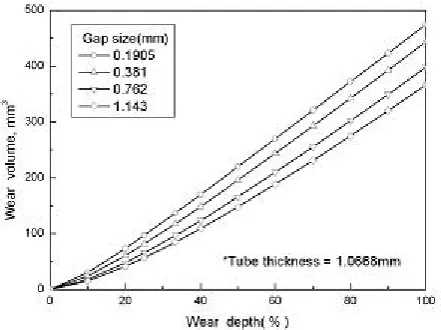
When the gap distances between the tube and support plate have a value of 0.1905mm(0.007inch), 0.381mm(0.015 inch), 0.762mm(0.03 inch) and 1.143mm(0.045 inch) the relations between worn depth and volume are obtained. The relation between worn thickness of tube and volume is show in Fig. 4. If h1 would be
equal to h2, the configuration of worn tube is a cylinder which is A1=A2 and the volume of cylinder, V is a
volume of cross sectional area.
As shown in Fig. 1 the wear volume decreases when tube to support clearance increases at given wear depth and at the given wear volume the wear depth increases with gap clearance. Axisa et al. calculated normal work rate by using the numerical model, in which both ends are simple supported beam with the gap at the mid-span. They obtained the results that when the turbulence alone was the cause of wear volume the wear rate decreases with the tube to support clearance’s increase. If the tube is fluid elastically unstable, then the volume wear rate increases with the gap clearance. If the present result is compared with Axisa ones, it was investigated that wear by a Connor’s beam model is caused under regions of flow induced vibration by turbulence.
Fig. 4 Wear volume versus wear depth with respect to gap between tube and its support
3.2 Comparison of wear depth calculated by exponential function for wear depth
The relation between tube wear and normal work rate has been derived by Au-Yang with the various wear coefficients through exponential function for wear depth. However he did not describe detailed method in his paper and the present result shows different values comparing with Au-Yang’s results. Therefore it is required the comparison with Au-Yang's results in his paper and results by Au-Yang’s method. In here, the relation between tube wear and normal work rate are independently calculated in detail.
In the case of the initial gap of 0.33mm and 0.66mm, the thickness loss rate, the characteristic time and the worn thickness of tube were obtained as 0.01582 mm/yr, 20.86 yrs and 0.2740 mm respectively. In calculation of n>0, the wear coefficient was used a value of 1.4E-15 Pa-1. Wear rate of tube through this study was obtained as 0.2740 mm for 10 years operating time, and this value is reported as 0.27mm in AU-Yang’s paper. Two results are well identical results for the predicted wear rate.
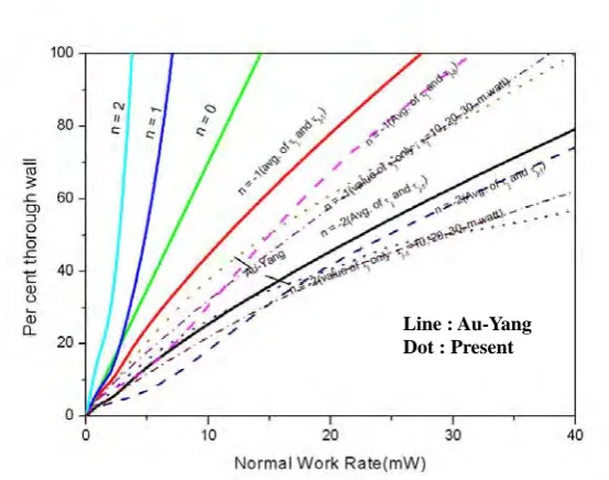
However in case of n≠1 and zero, Au-Yang’s result shows different values with present one. The difference of comparison of two results is large when the wear coefficient, k is 47.56E-15pa-1 found by Fisher and material constant, n is negative. The results found by present method and Au-Yang’s result are compared for n=-1, and n=-2 as shown in Fig. 5. In Fig.5 line is Yu-Yang’s results and dot line is present ones.
Using Eqs.(5), (6) and (7) and wear coefficients of 1.4E-15 Pa-1 and 47.56E-15pa-1, normal work rate and wear depth are also calculated for verifying the implementation of wear depth calculation by exponential function for wear depth. As a wear coefficient of 1.4E-15 Pa-1 is used the difference of present and Au-Yang's calculations are not much difference for all n values. However if wear coefficient of 47.56E-15pa-1 is used, then difference of the relation between the wear depth and normal work rate of two results are small for positive ‘n’ value, while in case of negative n value the difference of those obtained two methods are large. Its difference comes from the selecting method of characteristic time, τ. A characteristic time at Au-Yang’s method may be calculated by non-linear analysis. However it is calculated various method such as τi at iteration step, average
Fig. 5 Comparison of wear depth with respect to characteristic exponent, ‘n’ value
3.3 Methodology for wear prediction considering gap
A prediction method of wear depth of SG tube was proposed considering the gap between tube and its support. This method is similar to Au-Yang’s one, which is used the relation of normal work rate and wear depth of tube. For using this method, the characteristic exponent has to be got and the work rate values for each tube have to be calculated by some method.
Calculation methods for obtaining the work rate for each tube are adapted as following Eq. (9) (Yettisir and Pettigrew). The relations in Eq. (9) are selected for comparing with the wear rate by a prediction method of wear depth in Sec.2.1 and by those relations.
Model 1 :
∑
=
= 10
1 2 3 75 . 0
3 ( )
32
i s i L
R f Y
mL W
N π
,
Model 2 : π3 0.75 3 2ζ )
(
32 L s
R f Y
mL W
N =
, (9)
Model 3 : 16π3 3 2ζ /μ s
Y mLf W
N =
,
Model 4 : 8π3 3 2ζ/μ s
Y mLf W
N =
In this study, a tube of KSNP SG is selected as sampling case. The input values are used as followings; tube mass(m) is 0.849kg/m, length of tube between both supports(L) 3.069m, radius of tube upper bundle(R) 0.254m, the first natural frequency(f) 32.748HZ, maximum RMS value by turbulence excitation Yrms=1.3E-4m, damping
coefficient ζ =0.015, and friction coefficient μ=0.5. The above values are substituted to Eq.9 and each normal work rate are obtained followings; 9.29 mw, 2.6834 mw, 17.39 mw and 8.695 mw. Using the work rate model, wear volume, the wear volume could be calculated and the wear depth also is obtained by the relation of wear volume and depth.
Wear depth with operating time was also calculated by another method which is shown this paper Sec.2.1(Conners). In case of Model 4 for work rate calculation, two results i.e. methods by Yettisir and Conners are compared in Fig.6 with various wear coefficients. From references, each wear coefficient are selected as followings; k1=11.02E-15 m2/N, k2=18E-15 15 m2/N and k3=43.8E-1515 m2/N respectively.
Wear depth of Model 4 for obtaining the work rate by Yettisir and Pettigrew have a good agreement with tube depth by Conners’ method. Thus in case of KSNP SG, work rate model can be selected as
μ ζ
π /
8 3 3 s2
N mLf Y
W = .
Fig. 6 The comparison of tube depth for selecting the normal work rate model
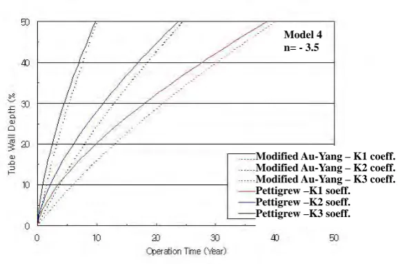
For obtaining the characteristic exponent, n, in the present prediction model which is modified Au-Yang’s model, it is compared with tube wall depth by modified Au-Yang and Pettigrew model. It is shown in Fig.7. When the characteristic exponent(n) was used as a value of -3.5, tube wall depth by present method reasonably agreed with prediction method of work rate by Pettigrew’s model 4 with operating time.
Fig. 7 The comparison of tube depth for selecting the characteristic exponent(n)
3.4 Estimation of wear depth considering gap
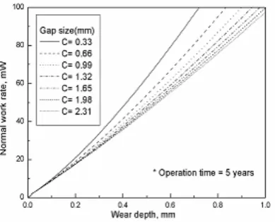
In section 3.4, a prediction method of wear depth considering gap was developed through obtaining the characteristic exponent(n) in the modified Au-Yang’s methodology and selecting a model to calculate the work rate. Using this proposed method, the relation of wear depth and normal work rate was investigated with respect to the operating time of 5, 10, 15, 20 years respectively. It is shown as Fig.8 ~ Fig.11 respectively. The characteristic time, τ is calculated the mean value of characteristic time of normal work rate xj and xj-1 using the
wear coefficient of 11.02E-15pa-1. The materials of anti-vibration bar(AVB) is stainless steel 405 and tube is made of alloy 600 steel and employed wear coefficient is 11.02E-15pa-1 . It was also applied to a case of the tube interaction system with anti-vibration bar. This method can be applicable to the tube interaction system with eggcrate type support plate by the same method except for calculating average initial wear depth rate, Δhin the present prediction method.
Pettigrew-Mode 4–K1 coeff. Pettigrew-Mode 4–K2 coeff. Pettigrew-Mode 4–K3 coeff. Conner’s Model –K1 soeff. Conner’s Model –K2 soeff. Conner’s Model –K3 soeff.
Modified Au-Yang – K1 coeff. Modified Au-Yang – K2 coeff. Modified Au-Yang – K3 coeff. Pettigrew –K1 soeff. Pettigrew –K2 soeff. Pettigrew –K3 soeff.
As shown in Fig. 8 ~ Fig. 11, difference of normal work rate between the initial gap(C) of 0.33 mm and 0.66 mm shows maximum difference and the difference of that is small as the gap increases. If the normal work rate is less than 10 mw using wear coefficients with generally accepted level, the effect of gap size on the normal work rate is negligibly small as shown in Fig. 8 ~ Fig. 11.
Throughout summarized results in Fig. 8 ~ Fig. 11, normal work rates are decreased as the gap between the tube and support is increased. It is investigated that as operating time increase, normal work rate for wear depth decrease. It is concluded that effects of gap decrease as operating time increase. It is generally stated that the normal work rate increases as the gap between the tube and support increases(Axisa) under the unstable conditions by fluid-elastic excitation. The present results calculated according to modified Au-Yang's method can not find the relationship of gap effect and normal work rate in the condition of fluid-elastic instability. Thus, a prediction method of wear depth considering gap can be applicable to estimating wear depth under the turbulence excitation fluid conditions.
Fig. 8 Wear depth vs. work rate according Fig. 9 Wear depth vs. work rate according
to the various gap sizes after 5 years to the various gap sizes after 10 years
4. CONCLUSIONS
The present paper has the final purpose for finding the relationship of tube wear depth and consuming time. The gap between tube and support is generally known as an important factor on steam generator tube wear in addition to the mechanical properties of tube and support. In order to achieve the purpose to establish the relationship of tube wear depth and operating time, the relation between the wear tube and normal work rate at given elapsed time has been derived using Connors and Au-Yang methodology and implemented to a tube of KSNP SG.
Firstly the relation between wear depth and operating time was derived and implemented using the wear coefficient, normal force and wear distance for various gap. The required time may be calculated considering wear depth equivalent to the wear volume obtained geometrically.
A prediction method of wear depth considering gap was derived and implemented a tube of KSNP SG by using the modified Au-Yang’s methodology. It could be carried out by the relation between the wear depth and the characteristic time which is the function of the wear coefficient and normal work rate.
1. A method of estimating the wear depth proposed by Connor is applicable to the fluid condition under regions of flow induced vibration by turbulence.
2. A work rate model of Yettisir et.al. could be selected as 8π3 3 2ζ /μ
s
N mLf Y
W = in case of KSNP SG. Results of tube depth through a selected model have a good agreement with tube depth by Conners’ method.
3. As tube wall depth by present prediction method reasonably agreed with ones of prediction method of work rate by Pettigrew’s model with operating time, the characteristic exponent, n may be used as a value of -3.5.
4. A prediction method for evaluating wear depth considering the gap effect can be applicable to the tube interaction system with eggcrate type support plate and anti-vibration bar support except for calculating average initial wear depth rate in the present prediction method.
5. By the proposed method, it is investigated that normal work rates are decreased as the gap is increased, and normal work rates are decreased as operating time is increased. It is concluded that gap effect is decreased as operating time is increased.
6. When the normal work rate is less than 10 mw using wear coefficients with generally accepted level, the effect of gap size on the normal work rate is negligibly small.
7. A proposed prediction method of wear depth considering gap could be applicable to estimating wear depth under the fluid conditions of turbulence excitation.
REFERENCES
[1] Connors. H. J., (1981), Nuclear Technology, Vol. 55, P. 381.
[2] Au-Yang, M. K., (1998), Transaction of ASME, Journal of Pressure Vessel Technology, Vol. 120, P. 138. [3] Axisa, F., Antunes, J., and Villard, B., (1988), ASME, Journal of Pressure Vessels, Technology, Vol. 110,
P. 6.
[4] Brennemann, B., and Gurdal, R. J., (1997), 4th International Symposium on Flow-induced Vibration and Noise, Dallas., Tx
[5] Hofmann, P. J., and Schettler, T., (1989), EPRI Report NP-6341, Research Projects S174-2, S 310-2, P4-13.
[6] Yetisir, M., Mckerrow, E., and Pettigrew, M. J., (1998), J. of Pressure Vessel Technology, Vol. 120, P. 297. [7] Yetisir, M., and Pettigrew, M. J., (1999), PVP-Vol. 389, Flow Induced Vibration ASME, P.273.