Volume 2009, Article ID 617818,15pages doi:10.1155/2009/617818
Research Article
Cross-Layer Explicit Link Status Notification to Improve
TCP Performance in Wireless Networks
Ji-Hoon Yun
Wireless Systems Lab., Samsung Electronics, 156-777 Suwon, South Korea
Correspondence should be addressed to Ji-Hoon Yun,[email protected]
Received 17 January 2009; Accepted 28 April 2009
Recommended by Lawrence Yeung
To alleviate the performance degradation of conventional TCP in wireless networks, many schemes have been proposed so far. One category of such schemes is the Explicit Loss Notification (ELN) scheme in which TCP senders are notified of wireless losses so as to avoid congestion control against those losses. Thus the key design factor of the ELN scheme is how to detect wireless losses accurately and rapidly. This paper proposes a new ELN scheme, in which wireless losses are detected by monitoring the operation of the wireless link layer. By exploiting such cross-layer design, the proposed scheme can detect wireless losses without additional transmission over the wireless link and thus achieves accurate detection with minimum delay. The proposed scheme additionally sends new information, that is, Explicit Retransmission Start Notification, in order to prevent spurious timeouts of the TCP senders. Furthermore, in order to handle packet reordering and avoid successive shrinking of a congestion window due to multiple packet drops, a new TCP modification is proposed. Through intensive simulations, it is demonstrated that the proposed scheme outperforms the other ELN schemes, and yields the throughput performance of more than 400% of TCP-Reno and 150% of Snoop in the considered environments.
Copyright © 2009 Ji-Hoon Yun. This is an open access article distributed under the Creative Commons Attribution License, which permits unrestricted use, distribution, and reproduction in any medium, provided the original work is properly cited.
1. Introduction
In recent years, wireless networks become more common in real life and many services such as mail, web browsing, e-commerce, and so fourth are available in the current wireless networks. In the near future, wireless networks will provide more services that are provided in the wired Internet, and will gradually carry the traffic similar to that of the wired networks. In the current wired networks, the majority of traffic relies on the Transmission Control Protocol (TCP) [1], which implies that the majority of traffic in the future wireless networks may also use TCP for the same services.
TCP is the prevailing transport layer protocol that provides the connection-oriented service and reliable trans-mission by acknowledgment (ACK). It also has a delicate congestion control mechanism [2] to deal with network congestion in a distributed manner. However, it is reported that TCP suffers from severe performance degradation in wireless networks [3].
TCP was originally designed for the use in the wired networks comprising reliable wired links and stationary
hosts. It assumes that packet losses and unusual delays result from congestion in the network. Thus a TCP sender reduces its congestion window size to alleviate the congestion when it identifies the loss of a packet either by the arrival of several duplicate ACKs or the absence of an ACK for the packet within a timeout interval. However, wireless links can also suffer from packet losses due to high Bit Error Rate (BER), collisions in random access channels and handoffs in mobile networks. We refer to such packet losses as wireless losses to differentiate them from congestion losses. Although a packet is lost in the wireless link, not by congestion, the TCP sender reduces its congestion window size because the packet loss assumes that it is due to congestion in the network. Such TCP behavior results in significant throughput degradation and high interactive delay.
schemes, and link-layer schemes. The end-to-end schemes mostly use three techniques, that is, selective acknowledg-ments [5], Explicit Loss Notification (ELN) [6–10], and Bandwidth Estimation (BWE) [11–15]. (We do not consider the split-connection schemes in this paper because they violate the end-to-end semantics of a transport layer protocol considerably and put much overhead on the base station.)
In ELN schemes, the TCP sender is notified of wireless losses to preserve its congestion window. Although an ELN scheme is used, the TCP sender may reduce its congestion window even due to a wireless loss if the corresponding loss notification arrives too lately or if the detection of the wireless loss fails. Thus, how accurately and rapidly wireless losses can be notified is the main concern of ELN schemes. There have been various proposals which attempt to achieve this goal. In Balakrishnan et al.’s scheme [6], the TCP sequence numbers are cached at a Base Station (BS), and if the packet whose sequence number is cached is lost, the ELN bit of the ACK packet is set active by BS. In TCP HACK [7], the TCP sender puts extra header checksum bits in the options field of the TCP header. If the TCP receiver receives a data segment of which the data portion is corrupted while the header is intact, the receiver considers it to be a wireless loss and sends an ACK with the reserved bit for ELN set. EWLN [8] and TCP-ELN [9] are based on the similar idea. LHP [10] tries to improve the detection probability by fragmentation. In LHP, each data frame is fragmented before being transmitted over the wireless link and the first fragment which contains the TCP/IP header is sent repeatedly prior to the rest of fragments until it is successfully transmitted or all allocated link time slots for the frame are exhausted. If the receiver does not receive the whole frame except the first fragment, the receiver regards it as a wireless loss and sends an ACK packet with the ELN bit set.
However, the previous ELN schemes have long detection delay and nonzero detection failure probability. Balakrishnan et al.’s scheme requires an exchange of additional data and ACK packets over the wireless link for the detection of a wireless loss, which adds additional transmission delay to the detection delay. The delay gets even longer in poor channel condition due to frequent retransmissions. The other schemes require that a certain part of a data packet should be transmitted successfully in order to detect its wireless loss. However, if the wireless channel condition is poor, there is the possibility that such a part is also corrupted. Also, handoffor collision may result in the loss of the whole packet. In such cases, the TCP receiver will not detect the wireless loss correctly. Even though the receiver detects the wireless loss correctly, the ELN ACK should be transmitted over the wireless link. This takes an additional delay until loss notification and increases the possibility of notification failure further.
Meanwhile, a TCP sender can invoke congestion control due to the acknowledgment timeout of a packet while BS is still attempting to transmit the packet in the wireless link. This is calledspurious timeoutand more likely to occur if BS has slow loss recovery mechanism (e.g., 80∼100 milliseconds for loss awareness in UMTS Rel’99) [16]. The above schemes cannot prevent spurious timeout because their notification
process gets started after BS finishes the whole transmission procedure for a packet.
In this paper, a new ELN scheme, called (Link Layer originated Explicit Link Status Notification) LL-ELSN, is proposed. LL-ELSN does not require additional transmission over a wireless link for loss notification and thus enables accurate detection with minimum delay. This is achieved by exploiting cross-layer design. The key idea of LL-ELSN is to send ELN when a data frame is discarded at the wireless link layer due to excessive retry. Along with ELN, the proposed scheme sends a new information, that is, Explicit Retransmission Start Notification (ERSN), which notifies the TCP sender of the start of the retransmission process at the wireless link layer, in order to prevent spurious timeouts at the TCP sender. The author also proposes an SACK-based TCP modification, that is, ELN-capable SACK (ESACK), which can handle ELN messages and packet reordering due to the immediate retransmission of a lost packet indicated by ELN. ESACK is designed to avoid consecutive invocation of congestion control when multiple packets of a congestion window are dropped due to congestion. ESACK also miti-gates bandwidth waste due to continuous ELN generation in a disconnection by appropriately filtering received ELNs according to their causes.
To investigate the performance improvement of the pro-posed scheme, we perform simulation using ns-2 [17] and compare various wireless TCP schemes. Through simulation, it is shown that the combination of the proposed ELN scheme and ESACK achieves goodput performance of more than 400% compared to TCP-Reno and 150% to Snoop [18]. Consequently, we demonstrate that the proposed scheme, when combined with the Link Layer Automatic Repeat Request (LL-ARQ) using a small retry limit, achieves consistently good performance against both uniform and bursty channel errors. Moreover, considering that many wireless TCP proposals compare their schemes only with TCP Reno or a few other schemes, our simulation results provide a comprehensive performance comparison of the various schemes on a single simulation platform.
We only consider last-hop wireless networks, that is, only the link between BS and user equipments is wireless, such as cellular networks and infrastructure Wireless Local Area Networks (WLANs).
The rest of this paper is organized as follows.Section 2
briefly describes recent wireless TCP schemes and analyzes their pros and cons. InSection 3, we describe the implemen-tation details of LL-ELSN and compare it with other ELN schemes.Section 4explains ESACK, andSection 5presents the simulation results and their analysis. We conclude this paper inSection 6.
2. Related Work
2.1. Explicit Loss Notification Schemes. ELN schemes attempt to detect wireless losses and notify the TCP sender of their occurrences by marking the reserved bit of TCP ACK or sending a newly defined message. Accordingly, how to accurately detect wireless losses and how to rapidly notify them are important design factors in ELN schemes.
In TCP HACK [7], the TCP sender puts extra header checksum bits in the options field of the TCP header. If the TCP receiver receives a data segment of which the data portion is corrupted while the header is okay, the receiver considers it as a wireless loss and sends an ACK with the reserved bit for ELN set to one. HACK assumes that SACK is used basically and the sender, upon reception of the ACK with the ELN bit set, immediately retransmits the lost packet without triggering congestion control. However, in HACK, if the wireless channel condition is poor, there is the possibility that the header is also corrupted. Also, handoffor channel contention may result in the loss of the whole packet. In such cases, the TCP receiver cannot judge the wireless link error correctly. So, the TCP sender of HACK can reduce its congestion window even due to a wireless loss. Even though the receiver detects the wireless loss correctly, the ELN ACK should be transmitted over the wireless link. This takes an additional delay until loss notification and increases the possibility of notification failure further.
LHP [10] tries to improve the detection probability by fragmentation. In LHP, each data frame is fragmented before being transmitted over the wireless link and the first fragment that contains the TCP/IP header is sent repeatedly prior to the rest of the fragments until it is successfully transmitted or all allocated link time slots for the frame are exhausted. When the receiver does not receive the whole frame except the first fragment, the receiver regards it as a wireless loss and sends an ACK packet with the ELN bit set. By fragmentation, LHP can increase the transmission probability of the TCP/IP header portion, which after all improves the detection probability. LHP also utilizes selective acknowledgement and the packet list which manages congestion control by keeping the unacknowledged packets in the sending order. However, the first fragment has to be transmitted successfully, which increases detection delay. Moreover, the first fragment can still be lost. Also, ACK packets that notify the wireless loss should go through wireless medium and this increases the detection failure probability and the notification delay further. The packet list works poorly with detection failures because the sender retransmits packets redundantly and invokes congestion control if the notification fails. If SMART [20] is used for LHP, whenever an ACK is lost, congestion control is invoked because the SMART ACK only contains the information of the single packet which has been successfully received and has triggered the ACK. In addition, fragmentation increases header overhead considerably, especially in 802.11 [21].
2.2. Bandwidth Estimation Schemes. BWE schemes keep on estimating the available bandwidth to monitor the network state. If a packet loss occurs in a noncongestive state based on the estimated bandwidth, the TCP sender does not invoke congestion control or reduces a congestion window
conservatively. However, as BWE schemes infer the network state from indirect information, they have high probability of misjudgement.
TCP Westwood [11] estimates the available bandwidth from a low-pass filtered ACK reception rate. Its slow start and congestion avoidance phases are the same as those of TCP Reno. Ifnduplicate ACKs are received (nis typically 3), the sender sets the ssthreshandcwnd as the estimated bandwidth. When a timeout occurs, the sender sets the ssthreshas the estimated bandwidth and the cwndas one. In this way, it can maintain a proper sending rate even with wireless losses. However, the low pass filter incurs additional processing overhead due to its complexity. The filter also has the parameters whose optimal configuration may be different network by network. If ACKs are lost, the sender reduces its estimated bandwidth. For a timeout, it reduces thecwnd to one. Therefore, with wireless links having poor channel condition, TCP Westwood will underestimate the available bandwidth and have degraded performance since TCP ACKs can be also lost.
TCP Veno [12] adopts the measurement technique of Vegas [22] to estimate the network state. Veno does not change much of Reno. In the congestion avoidance phase, if the estimated backlogged segments N from the Vegas measurement is smaller than the thresholdβ, it assumes that the available bandwidth is not fully utilized and increases cwndby 1/cwndwhen each new ACK is received as in TCP Reno. If N ≥ β, it increases cwnd by 1/cwnd when every other new ACK is received, so as to reach the maximum achievable bandwidth rather slowly. Whennduplicate ACKs are received, if N < β, Veno assumes a wireless loss and reduces thessthreshandcwndby a small amount. Otherwise it behaves as TCP Reno. Veno has only two network states: congestion (N ≥ β) or noncongestion (N < β). In the congestion state, every packet loss is assumed to be a wireless loss. Therefore, Veno cannot appropriately handle wireless losses when the network is in congestion.
TCP-Santa Cruz [23] also uses the measurement tech-nique of Vegas to estimate the number of backlogged segmentsNin the network. It updates a three-state machine based on the changes of N. Within the state machine, an increase ofN during two consecutive intervals leads to the transition to the congestion state. TCP-Santa Cruz classifies a packet loss as a congestion loss and invokes congestion control against it only in the congestion state. However, TCP Santa Cruz has the same problem as TCP Veno has.
marking, which increases the network cost and processing overhead on the routers. Although it has less parameters than TCP Westwood, it still requires some parameters whose optimum values are hard to be decided because of their high dependence on network states. Also, it has no solution against timeouts due to wireless losses.
Jitter-based TCP (JTCP) [14] utilizes another metric, the jitter of data transmission time used in Real-time Transport Protocol (RTP) [25]. From the jitter reported by the receiver, it estimates the fraction of queued TCP segments in the network. If the number of queued segments estimated is more than a threshold, it behaves just like TCP Reno, except that it enters the fast retransmit phase only whennduplicate ACKs have been received over several Round-Trip Time (RTT). Otherwise it maintains ssthresh and cwnd for n duplicate ACKs or halvesssthreshandcwndfor a timeout. To calculate the jitter, the TCP sender has to store the sending time of each segment and the receiver has to report the segment receiving time in each ACK to the sender.
TCP TIBET [15] provides unbiased bandwidth estima-tion by filtering the interdeparture time of packets and the estimated bandwidth based on the core stateless fair queueing (CSFQ) algorithm. TCP TIBET uses the minimum RTT, denoted as RTTmin, to calculate the available bandwidth
accurately without depending on the coarse clock granularity of TCP. So, TCP TIBET has an RTTminupdating algorithm,
in which RTTmin is multiplied by a reducing factor less
than one. However, since the RTTmin updating algorithm
is invoked whenever a congestion event occurs, RTTmin
goes eventually to zero in congested networks. This makes ssthresh small, and hence the corresponding connection remain in the congestion avoidance phase.
TCP NewReno-FF [26] discriminates packet losses based on RTT variation. It uses the flip flop filter technique [27] to estimate RTT. The flip flop filter exploits two exponentially weighted moving average (EWMA) filters where one of them, called agile filter, gives more weight to recent RTT samples. The agile filter is used prior to the other one when the deviation of the measured RTT sample is within a certain limit. If more thanηRTT samples among the lastlsamples exceed the limit, a packet loss is classified as a congestion loss assuming that RTT will vary much in congestion. Otherwise it is classified as a wireless loss. As the other BWE schemes, it also has several parameters for configuring the filters and loss discrimination criterion. Moreover, it cannot detect wireless losses under congestion since it has only two network states as TCP Veno.
2.3. Another End-to-End Schemes. There are the end-to-end schemes which do not use the three techniques. TCP-DCR [19] is one of them. TCP-DCR delays a response to conges-tion by one RTT after the first duplicate ACK is received so that it gives time for LL-ARQ of the wireless link to recover a possible wireless error. If a new ACK arrives before the timer of one RTT expires, it switches to the normal operation. Otherwise it assumes that the loss is due to congestion and triggers the fast retransmissions and recovery operations.
With TCP-Casablanca [28], the TCP sender marks packets with two different discard priorities and intermediate
routers drop the packets of the lower priority first in congestion. Thus the probability distribution of congestion losses will be different for the two types of packets while that of wireless losses may be similar for both of them assuming the uniform distribution of wireless losses. The TCP sender exploits such a difference when determining the cause of a packet loss. However, TCP-Casablanca requires the change of every router in networks and this makes it hard to be deployed. It discriminates the cause of a packet loss in a stochastic manner, therefore has higher detection failure probability of wireless losses than ELN schemes. Furthermore, under heavy congestion or bursty-loss wireless channel condition, the probability distribution of packet losses may not follow the presumed one and thus the detection failure probability will increase.
3. Link Layer Originated Explicit Link
Status Notification
In this section, we describe the detailed operation of the proposed ELN scheme, that is, LL-ELSN, and analyze its behavior in the aspects of detection delay, accuracy, and bandwidth overhead.
3.1. Notification Operation. LL-ELSN assumes that the link layer protocol of a wireless link adopts an acknowledged ser-vice. The assumption is practical as many link layer protocols for wireless communication such as IEEE 802.11 Medium Access Control (MAC) [29] and Radio Link Protocol (RLP) [30] for cellular networks provide acknowledged services with ARQ. In such link layer protocols, when the number of retransmission attempts of a frame exceeds a limit, the link layer discards the frame and begins to transmit the next one. The discard of the frame results in the wireless loss of the corresponding TCP packet. In LL-ELSN, those discard events are monitored by BS or a wireless station. Here, BS indicates the network element which is responsible for reliable trans-mission over a wireless link in downlink communication, for example, Radio Network Controller (RNC) in UMTS [31] and Access Point (AP) in IEEE 802.11 WLANs.
TCP receiver
Corruption
CRC error (no L2 ACK transmission)
TCP sender
Queueing
BS BS
(No delay) L2 ACK timeout
1st retry
Last retry
Wireless link (L2 transmission)
Wired network
(a) (b)
No congestion control for
packet 1
Packet 1 ELN L2 ACK timeout
ERSN L2 ACK timeout
Queueing
TCP layer Link layer
TCP sender
Corruption
1st retry
Last retry
CRC error (no L2 ACK transmission)
Wireless link Packet 1
ERSN
ELN
Packet 1 Packet 1
L2 ACK timeout
. . .
. . .
Figure1: Behavior of the LL-ELSN scheme for (a) downlink communication, and (b) uplink communication.
Table1: Comparison of ELN schemes.
Balakrishnan et al.’s HACK, EWLN, TCP-ELN LHP LL-ELSN
ELN delay (downlink) Twls
data+Tackwls+Twrd Tackwls+Twrd Tackwls+Twrd Twrd ELN delay (uplink) Twls
data+Tackwls+ 2Twrd Tackwls+ 2Twrd Tackwls+ 2Twrd 0
Prob. of detection failure 0 Pf header Pffrag 0
ELSN agent
TCP
IP
Wireless link layer Wired link layer
ERSN/ELN to TCP sender (Flow information,
sequence number) of retransmitted or discarded frame
IP packet with (flow information, sequence number)
Traffic path
ERSN/ELN signalingpath
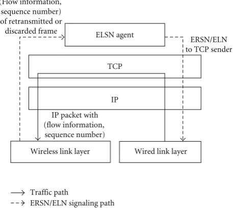
Figure2: Internal behavior of BS for ERSN and ELN generation for downlink connections.
destination IP address and port number are those of the TCP sender. To indicate the message type, that is, ERSN, ELN or legacy TCP ACK, two bits of the reserved field of
the TCP header are used. The internal traffic and signaling paths of BS for ERSN and ELN construction are depicted in
Figure 2for downlink communication. BS reads the TCP/IP header of an incoming packet from the wired network and sends the packet down to the wireless link layer with its flow information and TCP sequence number. When the first retransmission (excessive retry) occurs, the wireless link layer informs the ELSN agent of the flow information and sequence number of the retransmitted (discarded) packet. Then, the ELSN agent constructs the ERSN (ELN) message based on the information and sends it to the corresponding TCP sender.
For uplink communication shown in Figure 1(b), the link layer directly informs the upper TCP stack which packet enters a retransmission process and which packet is dropped because the monitored link layer and the TCP stack are within the same station. The behavior of the TCP sender against ERSN and ELN is the same as that in downlink communication. If a TCP packet is fragmented into several frames at the wireless link layer, ERSN is generated only for the first retransmission of a fragment while ELN is generated for the discard of the whole fragments.
in Table 1. For the comparison of notification delay, we define the following:
(i) the time when a wireless loss for a TCP packet occurs is the instance for the TCP packet being discarded at the wireless link layer;
(ii) the ELN delay is the time duration that takes until the TCP sender receives a notification for a wireless loss from the loss occurrence.
In the table,Twls
dataandTackwlsare the time that takes to transmit
a TCP data and an ACK packet successfully over a wireless link, and are obtained as
Twls
where Tdata and Tack are the required time for a single
transmission attempt of data and ACK packet, respectively, and Pdata and Pack are the transmission failure probability
of the corresponding packet.Twrd is the one-way trip time
between BS and the remote TCP node (either sender or receiver) in the wired network.
As shown in Table 1, the ELN delay of LL-ELSN is only Twrd for downlink communication. However, the
other schemes have additional delay plus Twrd since the
ACK packet corresponding to an ELN message has to be transmitted over a wireless link. Furthermore, Balakrishnan et al.’s scheme has another delay component for successful transmission of the next data packet. On the other hand, for uplink communication, LL-ELSN has negligible ELN delay because the TCP sender is notified of wireless losses by the link layer within the same station. The other schemes need additionalTwrdin uplink communication because the
wireless link and the TCP receiver are located separately. Although the other schemes (except LL-ELSN) have less delay than Balakrishnan et al.’s scheme, they have the probability of a detection failure that the TCP sender does not have any notification for a wireless loss (Pf header is
the probability that the header of the received TCP packet is corrupted and Pf frag is the probability that the first
fragment fails to be transmitted.). That is because at least the TCP/IP header and the first fragment have to be transmitted successfully over the wireless link. In LL-ELSN, there is no additional transmission over the wireless link and thus it has no detection failure in uplink communication. LL-ELSN also has no detection failure in downlink communication if ELN messages do not suffer from congestion losses on the wired path from BS to a TCP sender.
Compared to the other ELN schemes, LL-ELSN has the least delay and detection failure probability for both downlink and uplink, and also does not need any memory overhead at BS, which may enable fast handoffs. One disad-vantage of LL-ELSN is that it violates the layering semantics because the link layer refers to the TCP/IP header to send ERSN and ELN messages. However, cross-layer design [32,
33] is a currently popular trend to utilize the restricted bandwidth of wireless links as much as possible. Thus the violation of the layering semantics could be acceptable if the performance is the most important metric.
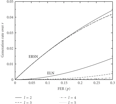
3.3. Bandwidth Overhead of ERSN and ELN. In order to investigate the bandwidth overhead of the ERSN and ELN messages to wired networks in downlink communication, we conduct a simple mathematical analysis. We consider the slotted-access wireless system in which a data transmission and the acknowledgement of its reception (or Layer-2 ACK timeout) over a wireless link takes a single slot. Denotepas the frame error probability of the wireless link andlas the retry limit. Then, the intergeneration timeI of ERSN and ELN is given as
I=
where E[RT] is the expected number of required slots for successful transmission of a data frame given that it is successfully transmitted within the retry limit. E[RT] is obtained as
LetTbe the duration time of a slot andrbe the transmission bit rate of the wireless link. We assume that the data transmission time is a dominant factor in a slot time and thusT P/r (P is the length of a data frame). Then, the generation rate Rof the ERSN and ELN messages, that is, their bandwidth overhead, is expressed as
R= L
IT
Lr
IP, (4)
where L is the message length of ERSN and ELN. When
L/P = 0.2, Figure 3 shows that R is below 5% of r in
the considered range of p. Knowing that the bandwidth of wired links is usually larger than that of the wireless link, the bandwidth overhead of the ERSN and ELN messages will not be a big burden to wired networks.
4. ELSN-Capable SACK
The operation of the TCP sender needs to be redesigned to handle the received ERSN and ELN messages. In this section we describe the proposed TCP modification which can be used with LL-ELSN as well as generic ELN schemes.
ERSN
Figure3: Bandwidth overhead of ERSN and ELN messages versus. FERpfor different retry limit valuesl.
Figure4: Example behavior of the LHP packet list against multiple packet drops in a congestion window.
information of sent packets, that is, sequence number and duplicate ACK counter, in the sending order. By exploiting this packet list (referred to as LHP packet list hereafter), the TCP sender can invoke appropriate congestion control schemes in various situations. However, it invokes multiple fast retransmit and recovery procedures for multiple packet drops in a congestion window, which makes the congestion window size unnecessarily small. To illustrate, assume that a list first has packet sequences from 14 to 19, as shown in
Figure 4, and packets 14, 16, and 18 are lost in the network. When the sender receives an ACK of (14, 15) which means the receiver received the packet 15, but has not received the packet 14 yet, it removes the element of packet 15 in the list and increases the duplicate ACK counter of packet 14 by 1. (LHP premises the use of selective acknowledgement (e.g., SACK) and thus, from a received ACK, the TCP sender can
be aware which packet triggered the ACK as well as which packet is expected.) Following ACKs for packets 17 and 19 increase the duplicate ACK counter of packets 14, 16, and 18. In this manner, the duplicate ACK counter of packet 14 reaches three, and a fast retransmit and fast recovery events are invoked, in which the congestion window size is reduced to half. After that, when the sender receives the ACK of (14, 20), it invokes the congestion control again because the duplicate ACK counter of packet 16 also reaches three. Consequently, the fast recovery is invoked three times for three packet drops in a congestion window.
To avoid this problem, we propose a new TCP modifi-cation, ELN-capable SACK (ESACK), which is based on the SACK implementation. In SACK, the data sender is assumed to have a retransmission queue which contains the segments, which have been transmitted, but not yet acknowledged, in a sequence-number order. Each segment in the retransmission queue has a flag bit “SACKed” to indicate whether this segment has been reported to have been received in an SACK option. ESACK adopts a similar approach except that the retransmission queue is aligned in a sending order. The retransmission queue does not need to store whole segments. Instead, it can store only the start and end bytes of a segment in the bulk data to reduce the size of the queue. ESACK defines new variables as below.
(i) FirstUnsacked: the sequence number of the first segment which is not SACKed in the retransmission queue.
(ii) HighSACK: the highest sequence number which is SACKed.
The FirstUnsacked segment should be acknowledged cumulatively or selectively by a very next ACK unless it is reordered or dropped by congestion. If the segment is lost in a wireless link, it will be notified by an ELN and the entry of the segment will be moved to the tail of the retransmission queue after being retransmitted. Therefore, if FirstUnsacked is identified to be less than HighSACK after a duplicate ACK is processed, the TCP sender understands that the FirstUnsacked segment is reordered or dropped by con-gestion assuming that ELN is not dropped. Thus, by checking FirstUnsacked and HighSACK of the retransmission queue, the TCP sender can react to congestion while processing ELN. The procedure of ESACK when an ACK is received is specified inAlgorithm 1.
When an ELN is received, ESACK retransmits the lost segment indicated by the ELN immediately since the recep-tion of an ELN indicates not only a packet was corrupted in a wireless link but also the packet has been dropped from the network. Thus the immediate retransmission ensures that the TCP connection remains ACK-clocked.
if(ELN) retransmit(ELN) else if(duplicate ACK)
if(there is a SACK option) update retransmission queue end if
if(HighACK==FirstUnsacked) dupacks ++
else if(FirstUnsacked<HighSACK) if(FirstUnsacked is changed)
dupacks=1 else dupacks ++
else if(HighACK segment is SACKed) retransmit(HighACK)
end if end if
if(dupacks>=DupThresh)
Typical TCP operation for DupThresh duplicate ACKs end if
Algorithm1: Pseudocode of ESACK congestion control algorithm.
of the highest byte of data that has been cumulatively ACKed at a given point in [34].) Otherwise, if FirstUnsacked is less than HighSACK, it means that the FirstUnsacked segment was reordered or dropped due to congestion while waiting for a new ACK for the segment retransmitted by an ELN. If the segment of HighACK is already SACKed, it means that the segment was dropped in the receiver queue. Therefore, the segment needs to be transmitted again. If the counter of received duplicate ACKs becomes three, the sender triggers the congestion recovery algorithms of fast retransmit and recovery. In fast retransmit phase, the sender retransmits the FirstUnsacked segment. The other operations of ESACK are equal to SACK. Therefore, if there is no wireless loss, ESACK behaves just like SACK.
4.2. ELN Filtering. When a TCP receiver is disconnected from BS in downlink communication, the transmission attempts of the frames for the disconnected receiver fail consecutively. If the BS keeps on sending ELN messages for those frames to the corresponding TCP sender, the TCP con-nection will not be removed since the TCP sender keeps on retransmitting the lost segments. This wastes the bandwidth of the wired network unnecessarily. One solution to avoid this problem is to let the BS stop sending ELN messages for disconnection. The BS can assume disconnection when a certain number of successive segments for a connection are discarded. However, this approach is not scalable since the BS should store per-connection information. We solve this problem in the sender side.
ESACK can solve the bandwidth waste problem due to consecutive ELNs by differentiating the causes of the ELNs: channel noise or permanent disconnection. ESACK assumes that channel noise can maximally result in N consecutive ELNs. To obtain the appropriate value of N, let p be the probability that a transmitted frame is corrupted by channel noise and r be the retry limit. Then, the probability that a transmission leads to at least k consecutive transmission
failures is obtained by prk. We configure N so that prN is reasonably high. For example, assume thatpis 20% and there is no retransmission (r =1). Then, the probabilities of two and three consecutive failures are 4% and 0.8%, respectively, and we can configureNas 2 since three consecutive failures due to channel noise is rather rare as 0.8%. For more conservative operation, we can increaseN. For those wireless losses due to channel noise, the TCP sender retransmits the discarded segments immediately without invoking con-gestion control. If ELNs are received for more than N successive data packets, we consider this a disconnection. In this case, the TCP sender freezes all the TCP-related parameters and retransmits the discarded segments at every other ELN. By doing this, ESACK can reduce the bandwidth waste of unnecessary retransmission due to consecutive ELNs gradually in permanent disconnection. The reason of gradual slow down is for the case when a wireless station temporarily looks disconnected due to deep fading, handoff, and so fourth If the TCP sender receives a new ACK, the TCP sender restores the parameters and resumes data service.
5. Simulation Results
To investigate the quantitative performance of the proposed scheme, we perform comprehensive simulation using the ns-2 simulator [17].
n n S
S
S
10 M
10 M 10 M 11 M
R R R
D
D
D
Figure5: Simulation network for downlink communication.
are full-duplex 10 Mbps and their buffers have delay offset doff. Each connection carries long-live FTP application traffic
from the source node (S) to the destination node (D). Packets are dropped bidirectionally at the wireless link. We generate bit errors depending on the given frame error rate (FER) in the wireless link. So, data packets are more prone to be lost than ACKs due to the longer length.
5.2. Comparison of Wireless TCP Schemes. In this subsection, we compare the various aspects of wireless TCP schemes. We first set the retry limit of 802.11 MAC to one in order to investigate the robustness of the testing schemes against wireless losses while excluding the effect of LL-ARQ. In this case, FER of the wireless link is equal to the Packet Error Rate (PER). It is noted that wireless losses due to collisions are not counted in FER, so there are still wireless losses even with small FER.
We perform the simulation of one TCP connection case, n=1.Figure 6shows the goodput result as FER varies from 0.001% to 9%. In the result, LL-ELSN shows significant performance improvement over the other schemes. Note that LL-ELSN is better than the other schemes even with 0.01% FER since there are still wireless losses due to collisions between data packets (from BS) and TCP ACK packets (from the wireless station). Snoop shows the second best perfor-mance due to its local retransmission at BS. However, as FER increases, the goodput of Snoop decreases more drastically than that of LL-ELSN. That is because the local retransmis-sion causes TCP to lose its ACK-based clock due to long end-to-end delay in high FER while LL-ELSN lets the TCP sender keep on sending data due to its accurate detection of wireless losses. The other schemes are better than Reno, but are much worse than LL-ELSN.Figure 7shows the effect of RTT on the goodput performance. We indirectly vary RTT by adjusting the delay offsetdoffof each link buffer, that is, increase doff
to increase RTT. The goodput of TCP Reno is known as inversely proportional to RTT [39]. Similarly, the testing schemes also show decreasing goodput for increasing RTT. However, their sensitivities to RTT are different. Especially, TIBET and Westwood are worse than Reno in small RTT. LL-ELSN shows good performance constantly.
Since the importance of uplink communication is increasing, we also simulate the uplink communication scenario where the wireless station is the TCP sender. We assume that the Snoop agent is at the wireless station by symmetric operation. In Figure 8, LL-ELSN shows the best performance because LL-ELSN has negligible ELN delay in uplink communication. However, Snoop is much worse than in downlink communication due to its slow retransmission. Snoop cannot retransmit the lost packet
Goodput
(Mbps)
0 0.6 1.2 1.8 2.4 3 3.6
FER
10−4 10−3 10−2 10−1
Reno SACK
Snoop LL-ELSN (a)
Goodput
(Mbps)
0 0.6 1.2 1.8 2.4 3 3.6
FER
10−4 10−3 10−2 10−1
Veno Westwood Jersey JTCP
TIBET HACK LHP DCR (b)
Figure6: Goodput comparison in downlink communication (n=
1,doff=10 miliiseconds).
until the Snoop agent receives a duplicate ACK, which takes one RTT in uplink communication, or a timeout occurs at the agent. Moreover, Snoop cannot distinguish congestion losses from wireless losses in uplink communication, thus Snoop is not suitable for uplink communication. The relative performances of the other schemes are similar to those in downlink communication.
Goodput
(Mbpt)
0 0.8 1.6 2.4 3.2
Delay offset of link buffer (ms)
2 10 20 30
Reno SACK Veno TIBET HACK LHP
Westwood Jersey JTCP Snoop DCR LL-ELSN
Figure7: Goodput versus delay offset of link buffer (n=1, PER=
1%).
even with small number of connections. However, the other schemes can fully utilize the bandwidth with sufficiently large number of connections since each connection suffers from rate reduction due to wireless losses. In order to quantify fairness among multiple TCP connections, we evaluate the Jain’s fairness index [40] which is defined as below
F(x)= (
xi)2 nx2
i
, (5)
where xi is the goodput of ith connection among the total n connections. F(x) ranges from 1/n to 1.0, where F(x) = 1.0 means the perfect fairness and in that case, all the connections occupy the same bandwidth. F(x) = 1/n means that one connection occupies the whole bandwidth. InFigure 10, the fairness of TCP-Jersey and JTCP gets worse as the number of connections gets increased. TCP Westwood and TIBET show the poor fairness as some connections suffer severely from frequent timeouts due to small congestion window size. Although the fairness of the testing schemes are relatively comparable with each other, most of them achieve high fairness index above 0.98 and do not suffer from severe unfairness. From the above two figures, we can conclude that LL-ELSN achieves good performance against wireless losses by accurate congestion response, not by aggressive behavior. To investigate the performance against both wireless and congestion losses, we introduce background traffic to the network along the path of a TCP connection. The background traffic follows the Pareto distribution whose mean rate is 8 Mbps and the shape parameter is set rather high as two to induce high dynamics to the network. The simulation result is shown inFigure 11. LL-ELSN still shows the best performance among the testing schemes, which
Goodput
(Mbps)
0 0.4 0.8 1.2 1.6 2 2.4 2.8
FER
10−4 10−3 10−2 10−1
Reno SACK
Snoop LL-ELSN (a)
Goodput
(Mbps)
0 0.4 0.8 1.2 1.6 2 2.4 2.8
FER
10−4 10−3 10−2 10−1
Veno Westwood Jersey JTCP
TIBET HACK LHP DCR (b)
Figure8: Goodput comparison in uplink communication (n=1, doff=10 miliiseconds).
means that it successfully handles congestion losses as well as wireless losses. The severe performance degradation of LHP is due to multiple fast recoveries. This fact is investigated further in the next subsection.
Goodput
(Mbps)
0 0.6 1.2 1.8 2.4 3 3.6
Number of TCP connections
5 10 15 20 25
Reno SACK Veno Westwood Jersey JTCP
TIBET HACK LHP Snoop DCR LL-ELSN
Figure9: Goodput versus of TCP connections (PER=1%,doff=20 milliseconds).
Ja
in
’s
fair
ness
inde
x
0.9 0.92 0.94 0.96 0.98 0.99 1
Number of TCP connections
5 10 15 20 25
Reno SACK Veno Westwood Jersey JTCP
LHP Snoop LL-ELSN TIBET DCR HACK
Figure10: Fairness versus of TCP connections (PER=1%,doff=20
milliseconds).
TCP Reno are replaced one by one with those using a new TCP variant. If the goodput of a Reno connection remains the same, it means perfect friendliness of the new TCP variant. Otherwise, the goodput decreasing rate of a Reno connection presents the degree of the unfriendliness of the new TCP variant with TCP Reno.Figure 12shows the result.
Goodput
(Mbps)
0 0.2 0.4 0.6 0.8
FER
10−4 10−3 10−2 10−1
Reno SACK Veno Westwood Jersey JTCP
TIBET HACK LHP Snoop DCR LL-ELSN
Figure11: Goodput with 8 Mbps Pareto background traffic (doff= 10 milliseconds).
Goodput
o
f
R
eno
connection
(Mbps)
0.2 0.3 0.4 0.5 0.6 0.7 0.8
Number of connections using a new TCP variant
1 2 3 4 5 6 7 8 9
Reno only Reno + SACK Reno + HACK Reno + DCR Reno + LL-ELSN
Reno + Veno Reno + Westwood Reno + TIBET Reno + ideal BWE
Figure12: Friendliness with TCP Reno (n=10).
Goodput
(Mbps)
0 1 2
Im
pr
o
vement
rat
io
(%)
0 10 20 30
N
u
mber
of
spur
ious
timeou
ts
0 10 20 30 40 50 60
FER
10−4 10−3 10−2 10−1
Without ERSN With ERSN Improvement
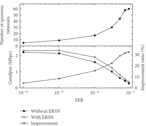
Figure 13: The number of spurious timeouts and goodput comparison with and without ERSN with the retransmission delay of 100 ms and the retry limit of 7 (n=1,doff=20 milliseconds).
Goodput
(Mbps)
0 0.8 1.6 2.4 3.2
Number of TCP connections
1 5 10 15 20 25
LL-ELSN + LHP LL-ELSN + HACK LL-ELSN + HACK-fixed
LL-ELSN + ESACK Reno
Snoop
Figure 14: Goodput comparison of different TCP modifications with LL-ELSN (PER=1%) whendprop=20 milliseconds.
the only factor for TCP-friendliness. Those four schemes setssthreshto the estimated bandwidth when a congestion event occurs. Therefore, when multiple fast recoveries or timeouts are invoked in a short-time period due to heavy network congestion, those schemes have largerssthreshthan Reno. While on the other, LL-ELSN and HACK show the similar result with SACK. That is because they behave just like SACK without wireless losses. TCP-DCR is somewhat aggressive against Reno as it delays congestion response, that is, reduction of transmission rate.
We also investigate the effectiveness of ERSN in the network with long retransmission delay. We set the
Im
pr
o
vement
rat
io
(%)
0 5 10 15 20 25
Rate of background traffic (Mbps)
1 2 3 4 5 6 7 8 9 10
Figure15: Performance improvement of ESACK compared to the LHP packet list.
retransmission delay of the wireless link layer to 100 milliseconds.Figure 13shows that the number of spurious timeouts increases as FER increases due to the increasing number of retransmissions. LL-ELSN with ERSN achieves higher goodput than that without ERSN thanks to the prevention of spurious timeouts. It is observed that the improvement ratio of ERSN is almost proportional to the number of spurious timeouts.
5.3. Effect of TCP Sender Operation. We compare several combinations of LL-ELSN and different TCP modifications to show the effect of TCP sender operation to the TCP performance and find which combination results in the best performance. We compare 4 different TCP modifications, TCP HACK, HACK-fixed, LHP packet list, and ESACK, when used with LL-ELSN.Figure 14shows the result. In the result, HACK shows better performance than Reno since it retransmits lost packets in the wireless link quickly. However, even with wireless losses, congestion control can be invoked by following duplicate ACKs and thus it is much worse than the other schemes. HACK-fixed is better than LHP when there are small connections, but, becomes worse than LHP when there are more than 10 connections due to congestion collapse by somewhat aggressive behavior. LHP is worse than ESACK because of ACK loss and multiple fast retransmit and recovery, as explained in Section 4. ESACK shows the best performance regardless of the number of connections, which means that it works well by accurate congestion response, not by an aggressive behavior.
Figure 15 shows the goodput improvement ratio of
Sending
ra
te
(Mbps)
0 0.2 0.4 0.6
Time (s)
0 5 10 15 20 25
Without ELN filtering With ELN filtering
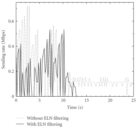
Figure16: Sending rate variation of ESACK in a disconnection with and without ELN filtering (n=10,doff=40 milliseconds,N=2).
Goodput
(Mbps)
0.8 1.6 2.4 3.2
FER
10−4 10−3 10−2 10−1
Reno-2 Reno-3 Reno-4 Reno-5 Snoop-2
Snoop-5 LL-ELSN-2 LL-ELSN-3 LL-ELSN-4
Figure17: Goodput versus. FER with different retry limit (n=1, doff=20 milliseconds).
Figure 16 shows the sending rate variation of ESACK
whose receiver is disconnected at 10 seconds. As shown in the figure, ESACK can avoid unnecessary retransmissions and thus mitigate bandwidth waste by filtering consecutive ELNs.
5.4. Effect of Link Layer ARQ. In this simulation, we only consider two best schemes in the previous simulations, that is, LL-ELSN and Snoop, and TCP Reno as a reference. If we use LL-ARQ, we can get much different results, as shown inFigure 17. When FER is less than 3%, TCP Reno
Goodput
(Mbps)
180 200 340 350 360
Retry limit
1 2 3 4 5 6 7
Reno-0.1 Reno-0.2 Reno-0.3 Reno-0.4 Reno-0.5
LL-ELSN-0.1 LL-ELSN-0.2 LL-ELSN-0.3 LL-ELSN-0.4 LL-ELSN-0.5
Figure18: Goodput versus. retry limit in the bursty loss channel with differentpbb(n=10,doff=20 milliseconds).
with the retry limit of two is better than Snoop because LL-ARQ can hide significant amount of wireless losses. Notwithstanding that Snoop performs local retransmission, Snoop shows worse performance than TCP Reno with LL-ARQ. It results from the slower retransmission of Snoop than LL-ARQ because the timeout time of Snoop should be larger than LL-ARQ’s and Snoop retransmits a TCP packet when a duplicated ACK is received or the timer expires. Also, Snoop does not retransmit TCP ACK which can be also lost, so this increases packet losses and delays the retransmission of data packets further. Although Snoop is combined with ARQ, it is worse than Reno with LL-ARQ because the retransmission mechanism of Snoop is independent of that of the link layer. That is, the Snoop agent can retransmit a TCP packet unnecessarily while the link layer keeps on retransmitting it. On the other hand, if LL-ELSN is combined with LL-ARQ, it shows better performance with relatively small retry limit than TCP Reno. It is because LL-ELSN lets the TCP sender not to shrink the congestion window against wireless losses which LL-ARQ cannot recover through retransmissions. From the result, it is shown that LL-ARQ achieves significant increase of goodput due to PER decrease in high-error conditions. Such a result is consistent with that of [42]. However, LL-ARQ has some disadvantages in wireless channels with bursty errors, as will be shown in the following.
Rayleigh fading channels and analytically proved its accuracy. Babich and Lombardi [44] proposed a first-order Markov model for three-level quantized Rayleigh fading channels. Zorzi et al.[45] showed that a two state Markov model well approximates Rayleigh fading channels. As such, modeling Rayleigh fading channels using a first-order Markov model has gained some acceptance in literature and seems to find a growing number of applications [28, 46]. The Markov chain considered in this paper consists of two states: good and bad. We assume that state transitions occur per frame transmission and all the frames are transmitted successfully except when collisions occur in the good state while all the frames are lost with probability one in the bad state. We set the transition probability from the good state to the bad state, denoted aspgb, to 0.01 and vary the staying probability in the
bad state, denoted as pbb, from 0.1 to 0.5. Aspbbincreases,
the burstiness of channel loss gets higher.
As shown inFigure 18, using LL-ARQ does not always perform well. Furthermore, the performance gets worse with LL-ARQ as the burstiness gets higher because, in the simulation environment considered, TCP performance is more sensitive to RTT increase rather than PER decrease due to LL-ARQ. Also, large retry limit results in the head of line (HOL) blocking in the First-In First-Out (FIFO) queue of BS (e.g., AP of 802.11 WLANs), so the other connections in the good state cannot be served due to a few connections in the bad state which keep on retransmitting failed frames until the retry limit is reached [47]. The HOL blocking also happens when a wireless station is suddenly powered-off during its communication with remote TCP senders. The harmful effect of HOL gets larger as the retry limit increases. Therefore, in order to achieve good performance flexibly in various environments, the retry limit should be set as small as possible satisfying the desired service quality in uniform error conditions.
6. Conclusions
In this paper, we proposed a new ELN scheme and a TCP modification. The proposed ELN scheme can detect wireless losses rapidly and accurately with minimum overhead since it does not need any additional data exchange over wireless links. We also showed that the proposed TCP modification can deal with multiple packet drops in a congestion window. The combination of these two schemes gives the significant performance improvement over existing protocols as we have demonstrated throughout the simulation results. We conclude that the combination of LL-ELSN and LL-ARQ with a small retry limit will perform well flexibly in various environments.
References
[1] J. Postel, “Transmission Control Protocol,” IETF RFC 793, September 1981.
[2] M. Allman, et al., “TCP Congestion Control,” IETF RFC 2581, April 1999.
[3] R. Caceres and L. Iftode, “Improving the performance of reli-able transport protocols in mobile computing environments,”
IEEE Journal on Selected Areas in Communications, vol. 13, no. 5, pp. 850–857, 1995.
[4] H. Balakrishnan, V. N. Padmanabhan, S. Seshan, and R. H. Katz, “A comparison of mechanisms for improving TCP performance over wireless links,”IEEE/ACM Transactions on Networking, vol. 5, no. 6, pp. 756–769, 1997.
[5] M. Mathis, et al., “TCP Selective Acknowledgment Options,” IETF RFC 2018, October 1996.
[6] H. Balakrishnan and R. H. Katz, “Explicit loss notification and wireless web performance,” inProceedings of IEEE Global Telecommunications Conference (GLOBECOM ’98), Sydney, Australia, November 1998.
[7] R. K. Balan, B. P. Lee, K. R. R. Kumar, L. Jacob, W. K. G. Seah, and A. L. Ananda, “TCP HACK: TCP header checksum option to improve performance over lossy links,” in Proceedings of the 20th Annual Joint Conference of the IEEE Computer and Communications Societies (INFOCOM ’01), vol. 1, pp. 309– 318, Anchorage, Alaska, USA, April 2001.
[8] B. Zhang and M. N. Shirazi, “Implementation of explicit wireless loss notification using MAC-layer information,” in Proceedings of the IEEE Wireless Communications and Network-ing (WCNC ’03), vol. 2, pp. 1339–1343, New Orleans, La, USA, March 2003.
[9] G. Buchholcz, T. Ziegler, and T. Van Do, “TCP-ELN: on the protocol aspects and performance of explicit loss notification for TCP over wireless networks,” in Proceedings of the 1st International Conference on Wireless Internet (WICON ’05), pp. 172–179, Budapest, July 2005.
[10] X. Gao, S. N. Diggavi, and S. Muthukrishnan, “LHP: an end-to-end reliable transport protocol over wireless data networks,” inProceedings of the IEEE International Conference on Communications (ICC ’03), vol. 1, pp. 66–70, Anchorage, Alaska, USA, May 2003.
[11] S. Mascolo, C. Casetti, M. Gerla, M. Y. Sanadidi, and R. Wang, “TCP Westwood: bandwidth estimation for enhanced transport over wireless links,” inProceedings of the 7th Annual International Conference on Mobile Computing and Networking (MOBICOM ’01), pp. 287–297, Rome, Italy, July 2001. [12] C. P. Fu and S. C. Liew, “TCP veno: TCP enhancement for
transmission over wireless access networks,”IEEE Journal on Selected Areas in Communications, vol. 21, no. 2, pp. 216–228, 2003.
[13] K. Xu, Y. Tian, and N. Ansari, “TCP-Jersey for wireless IP communications,”IEEE Journal on Selected Areas in Commu-nications, vol. 22, no. 4, pp. 747–756, 2004.
[14] E. H.-K. Wu and M.-Z. Chen, “JTCP: jitter-based TCP for heterogeneous wireless networks,” IEEE Journal on Selected Areas in Communications, vol. 22, no. 4, pp. 757–766, 2004. [15] A. Capone, L. Fratta, and F. Martignon, “Bandwidth
esti-mation schemes for TCP over wireless networks,” IEEE Transactions on Mobile Computing, vol. 3, no. 2, pp. 129–143, 2004.
[16] Nortel Networks, “HSDPA and Beyond,” white paper, 2005. [17] The Network Simulator-ns-2,http://www.isi.edu/nsnam/ns. [18] H. Balakrishnan, S. Seshan, and R. H. Katz, “Improving
reliable transport and handoffperformance in cellular wireless networks,”ACM Wireless Networks, vol. 1, no. 4, pp. 469–481, 1995.
[19] S. Bhandarkar, A. L. Narasimha Reddy, M. Allman, and E. Blanton, “Improving the robustness of TCP to Non-Congestion Events,” IETF RFC 4653, August 2006.
Communications Societies (INFOCOM ’97), vol. 3, pp. 1131– 1138, Kobe, Japan, April 1997.
[21] D. Qiao and S. Choi, “Goodput enhancement of IEEE 802.11a wireless LAN via link adaptation,” inProceedings of the IEEE International Conference on Communications (ICC ’01), vol. 7, pp. 1995–2000, Helsinki, Finland, June 2001.
[22] L. S. Brakmo and L. L. Peterson, “TCP Vegas: end to end congestion avoidance on a global internet,”IEEE Journal on Selected Areas in Communications, vol. 13, no. 8, pp. 1465– 1480, 1995.
[23] C. Parsa and J. J. Garcia-Luna-Aceves, “Differentiating con-gestion vs. random loss: a method for improving TCP performance over wireless links,” inProceedings of the IEEE Wireless Communications and Networking (WCNC ’00), pp. 90–93, Chicago, Ill, USA, September 2000.
[24] K. Ramakrishnan, et al., “The Addition of Explicit Congestion Notification (ECN) to IP,” IETF RFC 3168, September 2001. [25] H. Schulzrinne, et al., “RTP: A Transport Protocol for
Real-Time Applications,” IETF RFC 3550, July 2003.
[26] D. Barman and I. Matta, “Effectiveness of loss labeling in improving TCP performance in wired/wireless networks,” in Proceedings of the 10th IEEE International Conference Network Protocols (ICNP ’02), pp. 2–11, Paris, France, November 2002. [27] M. Kim and B. Noble, “Mobile network estimation,” in Proceedings of the 7th Annual International Conference on Mobile Computing and Networking (MOBICOM ’01), pp. 298– 309, Rome, Italy, July 2001.
[28] S. Biaz and N. H. Vaidya, ““De-randomizing” congestion losses to improve TCP performance over wired-wireless networks,”IEEE/ACM Transactions on Networking, vol. 13, no. 3, pp. 596–608, 2005.
[29] IEEE Std. 802.11-1999, Part 11: Wireless LAN Medium Access Control (MAC) and Physical Layer (PHY) specifications, Reference number ISO/IEC 8802-11:1999(E), 1999.
[30] 3rd Generation Partnership Project, Technical Specification Group Radio Core Network; Radio Link Protocol (RLP) for circuit switched bearer and teleservices. Release 6. 3GPP TS 24.022 (V.6.0.0), December 2004.
[31] 3rd Generation Partnership Project, Technical Specification Group Radio Access Network; HSDPA Overall Description. Release 7. 3GPP TS 25.308 (V.7.0.0), March 2006.
[32] X. Lin, N. B. Shroff, and R. Srikant, “A tutorial on cross-layer optimization in wireless networks,”IEEE Journal on Selected Areas in Communications, vol. 24, no. 8, pp. 1452–1463, 2006. [33] H. Jiang, et al., “Cross-layer design for resource allocation in 3G wireless networks and beyond,”IEEE Communications Magazine, vol. 43, no. 12, pp. 120–126, 2005.
[34] E. Blanton, et al., “A Conservative Selective Acknowledgment (SACK)-based Loss Recovery Algorithm for TCP,” IETF RFC 3517, April 2003.
[35] S. Floyd, et al., “The NewReno Modification to TCP’s Fast Recovery Algorithm,” IETF RFC 2582, April 1999.
[36] TCP Westwood modules for ns-2, http://www.cs.ucla.edu/
NRL/hpi/tcpw.
[37] TCP-DCR modules for ns-2, http://students.cs.tamu.edu/
sumitha.
[38] IEEE Std. 802.11b, Supplement to Part 11: Wireless LAN Medium Access Control (MAC) and Physical Layer (PHY) specifications: Higherspeed Physical Layer Extension in the 2.4 GHz Band, IEEE Std. 802.11b-1999, 1999.
[39] J. Padhye, V. Firoiu, D. Towsley, and J. Kurose, “Modeling TCP throughput: a simple model and its empirical validation,” in Proceedings of the ACM SIGCOMM Conference on Applications,
Technologies, Architectures, and Protocols for Computer Com-munication (ACM SIGCOMM ’89), pp. 303–314, Vancouver, Canada, October 1998.
[40] R. Jain, et al., “A quantitative measure of fairness and discrimination for resource allocation in shared computer systems,” DEC Research Report TR-301, Digital Equipment Corporation, Littleton, Mass, USA, 1984.
[41] J. Pahdye and S. Floyd, “On inferring TCP behavior,” in Proceedings of the ACM SIGCOMM Conference on Applications, Technologies, Architectures, and Protocols for Computer Com-munication (ACM SIGCOMM ’01), pp. 287–298, San Diego, Calif, USA, August 2001.
[42] D. Barman, I. Matta, E. Altman, and R. El Azouzi, “TCP optimization through FEC, ARQ, and transmission power tradeoffs,” inProceedings of the Wired/Wireless Internet Com-munications (WWIC ’04), vol. 2957 of Lecture Notes in Computer Science, pp. 87–98, Springer, 2004.
[43] C. C. Tan and N. C. Beaulieu, “On first-order Markov modeling for the rayleigh fading channel,”IEEE Transactions on Communications, vol. 48, no. 12, pp. 2032–2040, 2000. [44] B. Fulvio and G. Lombardi, “On verifying a first-order
Markovian model for the multi-threshold success/failure process for Rayleigh channel,” inProceedings of the 8th IEEE International Symposium on Personal, Indoor and Mobile Radio Communications (PIMRC ’97), vol. 1, pp. 12–16, Helsinki, Finland, September 1997.
[45] M. Zorzi, R. R. Rao, and L. B. Milstein, “On the accuracy of a first-order Markov model for data transmission on fading channels,” inProceedings of the 4th IEEE International Conference on Universal Personal Communications Record, pp. 211–215, Tokyo, Japan, November 1995.
[46] P. P. Pham, “Comprehensive analysis of the IEEE 802.11,” Mobile Networks and Applications, vol. 10, no. 5, pp. 691–703, 2005.