R E S E A R C H
Open Access
Performance of pilot-assisted channel
estimation without feedback for broadband
ANC systems using OFDM access
Iulia Prodan
1*, Tatsunori Obara
1, Fumiyuki Adachi
1and Haris Gacanin
2Abstract
Recently, broadband analog network coding (ANC) has intensively been studied due to its potential to increase the network capacity by exploiting the broadcasting nature of the wireless channel. However, channel state information (CSI) knowledge is required for self-information removal and signal detection. A low-complexity pilot-assisted channel estimation (PACE) scheme has been presented for broadband ANC, where feedback of the CSI estimates from the relay to the users is required. In this study, we propose a PACE scheme without CSI feedback from the relay for broadband ANC using orthogonal frequency-division multiplexing. In the first time slot the users transmit their respective pilots to the relay and in the second time slot the relay simply amplifies and forwards the received pilot signals to both users. Each user can then estimate all the CSI it needs for self-information removal and coherent signal detection, without requiring any feedback of the CSI estimates from the relay. We theoretically analyze the channel estimator’s mean square error (MSE) performance and evaluate the bit error rate (BER) and throughput performance of broadband ANC using the proposed PACE by computer simulation. The results show that the increase in the MSE of the proposed CE scheme causes only a slight BER performance degradation compared to the conventional PACE scheme with ideal feedback. However, the benefit of eliminating the CSI feedback can be seen in the throughput performance.
Keywords: Broadband ANC, OFDM, Channel estimation
Introduction
Next generation wireless communication networks will require very high capacity to cover the wide range of broadband services such as multicasting, video confer-ences, video on demand, etc., that evolve along with tech-nology development. This can be achieved by using higher modulation levels or multiple antennas systems such as multiple-input multiple-output (MIMO), but recently another method, based on embracing interference rather than suppressing it, has become a hot topic. In wired networks, network coding was proposed to increase the network capacity [1]. The same concept can be used in wireless networks to exploit the broadcasting nature of wireless transmission and further increase the network capacity [2,3]. It has been shown that for bi-directional
*Correspondence: [email protected]
1Department of Communication Engineering, Graduate School of Engineering, Tohoku University, Sendai, Japan
Full list of author information is available at the end of the article
wireless communication, network coding at the physi-cal layer (PNC) can double the network capacity [4]. Narrowband analog network coding (ANC) was intro-duced in [5] as a simplification of PNC where the signals from the two users are mixed in the wireless medium. In [6], broadband ANC was presented and it was shown that it requires channel state information (CSI) for self-information removal and coherent signal detection. Thus, accurate channel estimation (CE) is crucial to broadband ANC. As both users transmit at the same time, using the same frequency, we would have to allocate four time slots for pilot-assisted channel estimation (PACE) to avoid interference among users’ signals in the same time slot. However, this would decrease the spectrum efficiency of ANC systems.
In [7], a two-phase protocol for CE in two-way relay net-works is proposed, in which the CSIs of the equivalent channels are estimated through the least-square (LS) algo-rithm. Then, in order to overcome the interference of the
two pilot signals, considering the channel orders known, the CSI of the individual channels between each user and the relay are identified. Finally, the gains of the equiva-lent channels to be used for self-information removal and data detection are recomputed from the individual chan-nels. This algorithm requires the users to have a priori knowledge of the channel order. Moreover, it is shown in [7] that small overestimation of the channel order severely degrades the performance of the CE scheme. A complex maximum likelihood CE scheme for narrowband channels is presented in [8], in which the relay estimates the channel gains for both users and then it applies a power allocation algorithm to allocate power to different channel compo-nents so that the detection or CE at the user terminals is optimized. This scheme requiresa prioriknowledge of the channel cross-correlation coefficients of the narrowband channels and noise variance. A tensor-based CE scheme is presented in [9], in which the channel gains are esti-mated at the users’ side using a non-iterative algebraic solution to nonlinear LS problems. However, the scheme requires iterative refinement to approach LS–CE perfor-mance, and while it has lower computational complexity, it requires larger training overhead. Also, the scheme is designed without considering the effect of noise, which must be available a prioriif taken into consideration. A blind CE scheme has also been introduced for systems using M-PSK modulation exclusively [10]. The scheme is designed for systems that use constant-modulus signal-ing, and it provides lower overhead and a performance close to that of LS–CE, but is designed specifically for M-PSK systems.
Recently, a two-phase carrier frequency offset (CFO) and CE scheme that estimates the CSIs of the equivalent channels has been introduced [11]. This scheme has a high computational complexity, as it is utilizing a nulling-based LS estimation and the performance degrades in compar-ison to the scheme in [7] due to residual interference between the two pilot signals. Wang et al. [12] propose to superimpose pilots at the relay and then apply a com-plex algorithm to estimate the CFO and the CSIs of the equivalent channels. However, the scheme requires a large number of pilot tones or a large number of iterations of the estimation algorithm. In [13], a low-complexity two-slot PACE scheme that uses cyclically shifted pilot signals for the two users to avoid the pilot signals interference is introduced. The individual channels from the users to the relay are first estimated by the relay, and then sent to the users through feedback. However, the scheme assumes perfect CSI feedback from the relay to the users, and imperfect feedback causes additional errors in addition to bandwidth efficiency degradation.
In this article, we introduce a PACE scheme for broad-band ANC using orthogonal frequency-division multi-plexing (OFDM) that estimates the CSIs of the equivalent
channels, but unlike the work in [13], it does not require feedback from the relay. In the first stage, both users transmit their pilot signals to the relay. In order to avoid interference in the first time slot, the pilot signal of one of the users is cyclically shifted [14] to allow the signals to be separated in delay-time domain at the destination for CE. Then, unlike the work in [13], the relay does not estimate the individual CSIs, but rather broadcasts the received pilot signals to both users. Finally, the CSIs of the equiva-lent channels are estimated by the users. This way, we can have a simplified relay that does not need to do any pro-cessing, while also decreasing the overhead by eliminating the need of CSI feedback from the relay. We theoreti-cally analyze the mean square error (MSE) performance of the channel estimator and evaluate the performance with respect to the perfect CSI case and the CE scheme introduced in [13] (in this article referred to as “conven-tional PACE scheme”). We show that the proposed PACE scheme causes only a slight BER performance degradation from that of the conventional PACE scheme with ideal feedback, due to noise enhancement. However, the bene-fit from removing the feedback requirement can be seen in the throughput performance.
The rest of the article is organized as follows. The net-work model is presented in “Netnet-work model” section. “Channel estimation” section presents the proposed CE scheme, and the evaluation of the channel estima-tor’s MSE performance is shown in “Channel estimator performance analysis” section. “Numerical results” section shows some numerical results and discussions. We summarize our findings in “Conclusion” section.
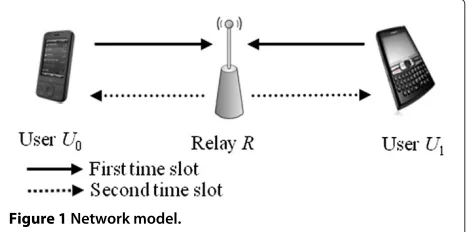
Network model
We consider a two-way relay network, with usersU0and U1 outside each other’s coverage area, communicating through the relayR, as shown in Figure 1. The communi-cation between the users and the relay uses time division duplex in two slots: in the first time slotU0andU1 trans-mit their signals to the relay and in the second time slot the relay broadcasts the received signal to the users through the amplify-and-forward (AF) protocol. In this article, we
assume that the channel between the users and the relay does not change during the two slots.
First time slot
The information bit sequence is channel coded and the encoded sequence is mapped to a complex-valued finite constellation such as quadrature phase shift key-ing (QPSK) modulation. The data-modulated symbol sequence of thekth userUkis represented by{dk(n);n=
0∼Nc−1}fork∈ {0, 1}. AnNc-point inverse fast Fourier
transform (IFFT) is applied to{dk(n);n = 0 ∼ Nc−1}
in order to generate the respective OFDM signals. An Ng-sample cyclic prefix (CP) is inserted as a guard
inter-val (GI), and the signals from the users are transmitted through the frequency-selective fading channel. The GI length is assumed to be longer than the maximum time delay of the equivalent channels, in order to maintain subcarrier orthogonality.
The frequency-domain received signal at the relay can be expressed as
Rr(n)=
1
k=0
2Ptdk(n)Hk(n)+Nr(n) (1)
forn=0∼Nc−1, wherePt(=Es/TcNc),Hk(n)andNr(n)
denote the transmit signal power of the users, the chan-nel gain between userUk and the relay, and the additive
white Gaussian noise (AWGN) at thenth frequency with single-sided power spectral density N0, respectively. Es
andTcdenote the symbol energy and the sampling period
of IFFT, respectively. Please note that in our system, for brevity, we consider both users to use the same transmit power. The problem of optimal power allocation has been approached in several papers, considering maximizing the system reliability [15] or fairness [16]. Also, Jiang et al. [8] propose a system in which the relay estimates the chan-nel parameters and allocates the power to the users to maximize the average effective signal-to-noise ratio of the data detection. However, this requires the relay to perform CE and the transmission of the power allocation param-eters increases the overhead. In this study, we propose a system with a simplified relay that does not need to do any processing such as CE, and try to minimize overhead, in this respect choosing a fixed power allocation scheme. While our power allocation scheme may not be optimal from the system’s performance (i.e., BER performance) point of view, it does not affect the channel estimator’s performance (i.e., MSE performance). This will be further discussed in the “Channel estimation” section.
Second time slot
The relay terminal normalizes the received signal shown in (1) by the factor G = 1/E[Rr(n)2] to make the
received average signal power unity and then broadcasts it
with transmit powerPr. The frequency-domain
represen-tation of the received signal at userUk’s receiver can be
written as
Rk(n)=
2PrGRr(n)Hk(n)+Nk(n) (2)
forn= 0 ∼ Nc−1, whereNk(n)denotes the AWGN at
the user side with single-sided power spectral densityN0. The kth user Uk removes its self-information and the
frequency-domain signal after self-information removal can be expressed as
˜
Rk(n)=Rk(n)−dk(n)Hk→k(n) (3)
forn= 0∼ Nc−1, whereHi→k(n)denotes the channel
between userUiandUkvia the relay, given byHi→k(n)=
2√PrPtGHi(n)Hk(n).
One-tap zero forcing frequency domain equalization (ZF-FDE) is then applied to obtain the decision vari-ables dˆk(n) = ˜Rk(n)Wk(n), where Wk(n) is the equal-ization weight for thenth subcarrier, given byWk(n) = H∗¯
k→k(n)/|Hk¯→k(n)|2. Here,(·)∗denotes the complex
con-jugate operation.k¯represents the index of the user that is the source of the data desired by userUk (i.e.,k¯ =1−k).
Thus,Hk¯→k(n)is the channel gain of the channel between
usersU0andU1. Since we consider that the channel gain does not change between the two transmission time slots, we have thatHk¯→k(n) = 2
√
PrPtGH0(n)H1(n). Finally, the equalized signal is demodulated and the decision variables are decoded using Viterbi algorithm.
The self-information removal and the ZF-FDE require knowledge of the equivalent channel gains, {H0→k(n); n=0∼Nc−1}and{H1→k(n);n=0∼Nc−1}. In
prac-tice, the equivalent channel gains must be estimated and we replace them in the self-information removal and the ZF-FDE processing by their estimates, denoted by
{ ˘H0→k(n);n=0∼Nc−1}and{ ˘H1→k(n);n=0∼Nc−1},
respectively.
Channel estimation
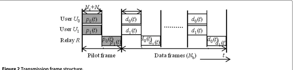
Our proposal is a PACE scheme with time-domain mul-tiplexed pilots. The transmission frame structure of the users and the relay is shown in Figure 2. Both the pilot and data frames are divided into two time slots, each of length Nc+Ngsamples. In the first time slot of the pilot stage,
both usersU0andU1transmit their respective pilot sig-nals,{p0(t);t= 0∼Nc−1}and{p1(t);t=0∼ Nc−1},
to the relay. Unlike the work in [13], where the relay esti-mates the channel and transmits it to the users, in our scheme during the second time slot the relay broadcasts the received superimposed pilot signals of the two users through an AF protocol. Consequently, the CE process-ing is done only at the users’ side; therefore, in our system the relay can be simplified, and by decreasing transmission overhead we further increase the bandwidth efficiency. The estimates of the equivalent channels are used in the followingNbdata frames for self-information removal and
equalization. The transmission process during the pilot stage is described below.
Pilot signal transmission
As shown in Figure 2, during the first time slot, usersU0 andU1transmit their pilot signals to the relay through a frequency-selective fading channel. The received pilot sig-nal{Rr,p(n);n=0∼Nc−1}at the relay can be expressed
in frequency domain as
Rr,p(n)=
1
k=0
2PtPk(n)Hk(n)+Nr(n), (4)
wherePk(n)is the frequency domain representation of the
pilot signal from userk.
While a large number of articles deal with ways to miti-gate the pilot signals interference, we choose an approach that allows us to avoid such interference. In order to avoid the problem of the two channel impulse responses over-lapping, we adapt a technique originally introduced in [14] for OFDM systems with multiple transmit antennas. The pilot signal {p1(t);t = 0 ∼ Nc−1}of user U1 is cyclically shifted byθ samples relative to user U0’s pilot signal {p0(t);t = 0 ∼ Nc − 1}, so that {p1(t) = p0 ((t − θ )modNc)}. The required value of θ depends on
the channel power delay profile (this will be discussed later). Thus, the pilot signal of userU1can be expressed in frequency domain as
P1(n)=P0(n)exp
−j2π θ n Nc
(5)
forn = 0 ∼ Nc−1, and the pilot signal received by the
relay can be written as
Rr,p(n)=
2PtP0(n)
H0(n)+H1(n)exp
−j2π θ n Nc
+Nr(n)
(6)
In the CE scheme, we propose that the relay handles the pilot frame in the exact same way it handles data frames, without performing any processing on the pilot signal it receives. It simply normalizes the received superimposed pilot signals by a factor of Gand broadcasts the mixed signal with powerPr.
After GI removal and Nc-point FFT, the
frequency-domain received signal{Rk,p(n);n= 0∼ Nc−1}at user Uk’s receiver can be represented as
Rk,p(n)=
2PrGRr,p(n)Hk(n)+Nk(n). (7)
This can be rewritten as
Rk,p(n)=P0(n)
H0→k(n)+H1→k(n)exp
−j2π θ n Nc
+ ˜Nk(n),
(8)
whereN˜k(n) =
√
2PrGNr(n)Hk(n)+Nk(n)denotes the
composite noise. As above,Hi→k(n)denotes the channel
between userUiandUkvia the relay, given byHi→k(n)=
2√PrPtGHi(n)Hk(n). We can see that the effect of the
transmit power is included in the equivalent channel gain we estimate; therefore, the proposed CE scheme can be used with any power allocation scheme.
Reverse modulation is applied toRk,p(n)to remove the
pilot as
˘
Hk(n)= Rk,p(n)
P0(n) =
H0→k(n)+H1→k(n)exp
−j2π θ n Nc
+ ˘Nk(n),
(9)
whereN˘k(n) = ˜Nk(n)/P0(n). Then, anNc-point IFFT is
applied to (9) to obtain the composite channel impulse response
˘
hk(τ )=h0→k(τ )+h1→k((τ−θ )modNc)+ ˘nk(τ ), (10)
whereh0→k(τ )andh1→k(τ )denote the desired impulse
responses of the channel from userU0, respectively, user U1, to userUk via the relay. The third term is the noise.
Note that due to the fact that the pilot of userU1is cycli-cally shifted byθ samples, the impulse response of the channel from this user has a delay ofθsamples, which sep-arates it from the impulse response of the channel from user U0 and allows us to estimate both channels at the same time.
A delay time domain window is used to separate the two channel impulse responses estimates as described in [13], by taking
˘
h0→k(τ )=
˘
hk(τ ) for τ =0∼Ng−1
0 elsewhere (11)
and
˘
h1→k(τ )=
˘
hk(τ+θ ) for τ =0∼Ng−1
0 elsewhere. (12)
Finally, an Nc-point FFT is applied to both channel
impulse response estimates,{˘h0→k(τ );τ = 0 ∼ Nc−1}
and{˘h1→k(τ );τ = 0 ∼ Nc−1}, to obtain the respective
estimates of the channel gains{ ˘H0→k(n);n=0∼Nc−1}
and{ ˘H1→k(n);n=0∼Nc−1}.
Estimated equivalent channel
We have seen that the proposed system estimates two equivalent channels at once, at each user side. As explained above, the impulse responses of the two equiv-alent channels are separated in delay time domain, due to the use of cyclically shifted pilots, which allows us to extract the channel impulse responses by applying simple filters.
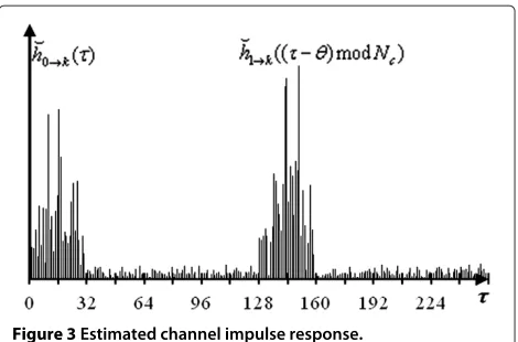
An example of an actual estimate of the channel impulse response at the receiver for a multipath channel with the number of sample-spaced pathsL = 16, whenNc = 256
subcarriers,Ng = 32 samples and θ = 128 samples, is
shown in Figure 3. It can clearly be seen from the figure that the channel impulse responses from the two users are completely separated in the delay time domain.
The channel gains we are trying to estimate are equivalent channel gains and are given by Hi→k(n) =
Figure 3Estimated channel impulse response.
2√PrPtGHi(n)Hk(n) for i,k ∈ {0, 1}. Therefore, the
impulse responsehi→k(τ )obtained by an inverse Fourier
transform is expressed by
hi→k(τ )=2
PrPt
Nc−1
t=0
hi(t)hk(τ−t). (13)
We can see that (13) is expressed as the convolution of two impulse responses; therefore, the maximum delay of the equivalent channel increases to up to the sum of the maximum delays of two original channels.
Figure 3 illustrates how the delay spread of the equiva-lent channels increases compared to the original channel impulse response. Therefore, the GI sizeNgand the cyclic
shift of the pilot signalθ must be set accordingly, in order to avoid inter-symbol interference (ISI) and overlapping of the two channel impulse responses. In our example, the equivalent channels that are estimated can be expressed as the convolution of two sample-spacedL-path channels. Thus, the maximum delay will become as high as double, and in order to avoid ISI and overlapping, we must have 2L ≤Ng ≤ θ ≤Nc/2 for the case of FFT sample-spaced
time delays.
The system we described in the “Network model” section uses a GI size larger than double the maximum delay of the individual channels, in order to comply with the constraints described above. However, increasing the GI size can be avoided at the cost of some signal process-ing at the relay. Gao et al. [7] proposed a method which removes the CP part of the received signal at the relay and adds a new CP that consists of the last symbols of the received signal. This way, a GI size equal to the maximum delay of the individual channels is sufficient for avoiding ISI.
Channel estimator performance analysis
We define the CE error at userUk for the channel from
userUias
ei→k(n)= ˘Hi→k(n)−Hi→k(n), (14)
and therefore the MSE for this channel is given by
MSEi→k(n)=E[|ei→k(n)|2] . (15)
Here,E[·] denotes the time average operation.
By using (10), (11), and (12) and by applying anNc-point
and by substituting it into (14), the error vector becomes
ei→k(n)=
Therefore, using (15) and (17), the MSE can be rewritten as
is the composite noise, and thus
E[N˘k(n)N˘k∗(n)]=
We consider a uniform power delay profile for the indi-vidual channels between the users and the relay and thusE[|Hk(n)|2]= 1 for alln. Also, considering that the
noise power is the same at the relay and the users side andE[|Nr(n)|2]= E[|Nk(n)|2]= 2σN2, we find that (18)
Note that in the case of a uniform power delay profile channel, the MSE has the same value for all subcarriers, which means the channel is estimated with the same accu-racy for all the subcarriers. Also, as we consider the noise power at both users sides equal, the MSE is not a function
ofiork, so in this case the accuracy is the same for any of the two equivalent channels estimated by any of the users. AsGis defined asG= 1/E[Rr(n)2], we use a longer
term average, so the value does not widely vary and affect the system’s performance, and thereforeG = 1/(4Pt +
2σN2). When we normalize the average MSE by the pilot signal’s total transmit power(=4PrPtG), we get
signal-to-noise power ratio at the users side and at the relay, respectively.
Similarly, we can evaluate the MSE for the equivalent channel gains for the conventional CE scheme with per-fect feedback (for details, please see Appendix), and we obtain
and thus we can conclude that the noise enhancement at the relay during the CE stage causes an MSE performance degradation of
MSE(n)= Ng Nc
SNR−r1. (23)
We want to emphasize the fact that this performance degradation is computed considering error-free feedback for the conventional CE scheme, as presented in [13], and is thus the upper limit to the performance gap. Inaccuracy of the CSI caused by noisy feedback from the relay in the conventional scheme is expected to further reduce the gap between the two schemes.
Numerical results and a comparison of the MSE perfor-mance of the two CE schemes are shown in the following section.
Numerical results
CE scheme introduced in “Channel estimation” are also presented. The parameters used in the simulation are summarized in Table 1. We assume an OFDM system with ideal coherent QPSK modulation and demodulation, Nc=256 subcarriers, andNg =32 samples. For forward
error control we apply rate-1/2 convolutional coding with the generator vectorsg1=(111)andg2=(101)with con-straint length 3. Hard decision Viterbi decoding is used. The propagation channel is FFT sample-spacedL = 16-path block Rayleigh fading, having a uniform power delay profile. For the pilot signal we use a Chu-sequence given by{p0(t) = exp(jπt2/Nc);t = 0 ∼ Nc−1} [17] and a
cyclic shift ofθ =128 samples. We can see from the net-work model that the tracking ability against fading in the CE is identical for the proposed and conventional PACE schemes. In order to compare the accuracy of the CE of the proposed scheme to that of the conventional scheme, we consider a quasi-static fading channel (i.e., the Doppler frequencyfDT →0) for the computer simulation.
Channel estimator’s MSE
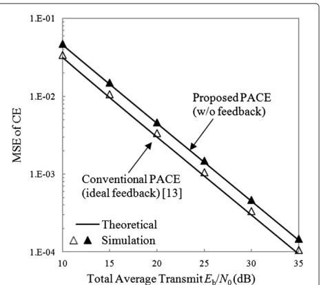
Figure 4 shows the MSE performance of the conven-tional and proposed CE schemes as a function of the total average signal energy per bit-to-AWGN power spec-trum density ratioEb/N0(=0.5(Pt+Pr)(1+Ng/Nc)(1+
1/Nb)Tc/N0). The lines show the theoretical MSE perfor-mance and the markers show the results of the computer simulation. We can conclude that the simulation results are consistent with the theoretical analysis, and they both show an increase in the MSE of the channel estimator of the proposed PACE scheme in comparison with that of the conventional scheme with ideal feedback. This increase is caused by the noise enhancement that occurs at the relay during the pilot stage. In the conventional scheme, the channels are estimated at the relay and at the users, and the pilot signals are not amplified and forwarded by the relay. In the proposed scheme, the relay forwards the pilot signals along with the noise added at the relay, thus the noise component during the estimation process is enhanced.
Table 1 Simulation parameters
Transmitter Data modulation QPSK
Block size Nc=256
GI Ng=32
Channel L=16-path block Rayleigh fading (uniform power delay profile)
Relay Protocol Amplify-and-forward
Receiver FDE ZF
CE Pilot-assisted (Chu seq.)
Figure 4Comparison of the channel estimator’s MSE performance.
However, we want to draw attention to the fact that the MSE of the conventional scheme is evaluated assuming error-free feedback of the CSI from the relay to the users; therefore, the curve in the graph represents the lower-bound limit. Perfect feedback poses great implementa-tion problems; in a practical system feedback errors are unavoidable, leading to further increase in the MSE of the channel estimator. This will reduce the performance gap between the two CE schemes.
BER performance
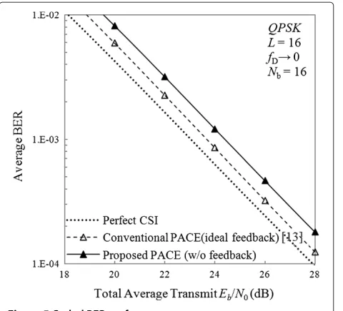
Figure 5 illustrates the BER performance as a function of the total average signal energy per bit-to-AWGN power spectrum density ratioEb/N0, under convolutional chan-nel coding. The power loss due to GI and pilot insertion is taken into consideration. We compare the performance of the broadband ANC system with the proposed CE scheme, denoted by “Proposed PACE (w/o feedback)”, to the case of perfect knowledge of CSI, denoted by “Perfect CSI” and the conventional CE scheme with ideal feedback introduced in [13], denoted by “Conventional PACE (ideal feedback)”.
Figure 5Coded BER performance.
BER performance for the conventional scheme is eval-uated under the assumption of cost-free, perfect CSI feedback from the relay to the users, and therefore rep-resents the lower limit of the BER in practical systems. We can conclude that the noise enhancement at the relay in the proposed PACE does not severely affect the BER performance of the system.
Although the proposed scheme shows a small degra-dation in the BER performance in comparison to the conventional CE scheme with ideal feedback, we empha-size the fact that the BER performance does not reflect the benefit the proposed scheme induces by eliminating feed-back. Depending on the feedback method employed with the conventional CE scheme, the throughput can become lower than that of the proposed scheme, due to reduced bandwidth efficiency and the BER performance degrada-tion caused by feedback errors. This is discussed in the following section.
Throughput performance
The throughput performance is illustrated in Figure 6 as a function of the total average signal energy per bit-to-AWGN power spectrum density ratio Eb/N0, with and without convolutional channel coding. We compare the throughput of the broadband ANC system with the pro-posed CE scheme, denoted by “Propro-posed PACE (w/o feed-back)”, to the case of perfect knowledge of CSI, denoted by “Perfect CSI” and the conventional CE scheme, intro-duced in [13], denoted by “Conventional PACE (ideal feedback)”. For the conventional CE scheme, we consider error-free feedback can be achieved at the cost of one time slot transmission.
It can be seen from Figure 6 that the system with prac-tical CE performs closely to the perfect CSI case, but we
Figure 6Throughput performance.
notice there is a gap between the upper limit in the high Eb/N0 region. The throughput gap between the perfect CSI knowledge and the proposed CE case is of 0.1 bps/Hz for the uncoded case and 0.05 bps/Hz for the coded case. The reason for this performance degradation is the fact that with practical CE, the system needs to transmit a pilot frame everyNbdata frames. When we compare the
performance of the two CE schemes, we notice that the proposed scheme has higher throughput than the conven-tional scheme with error-free, one time slot transmission feedback. We want to underline the fact that designing a feedback scheme is out of the scope of this work, and we only use this model as an example of the cost feedback can incur. We can see that in this case, there is a perfor-mance gap of 0.05 bps/Hz between the two CE scheme in the uncoded case, and 0.02 bps/Hz in the coded case. Therefore, we can see how the elimination of the feedback requirement can benefit the performance of the system.
We also notice that while channel coding significantly improves the throughput performance in the lowerEb/N0 region, the uncoded system has higher throughput the higherEb/N0region. We can conclude that the proposed CE scheme is a promising alternative for CE in broadband ANC systems where the feedback cost becomes higher than that of the BER performance degradation.
Conclusion
the CSI it needs for processing the data, there is no need for costly feedback from the relay to the users.
We evaluated the channel estimator’s MSE performance and compared it to that of the conventional PACE scheme that requires feedback of the CSI from the relay. We found that the MSE of the proposed scheme’s channel estimator shows a small increase compared to that of the conven-tional scheme with perfect feedback, because of the noise enhancement at the relay during the estimation process. The BER and throughput performance of an ANC sys-tem using the proposed CE scheme was also evaluated by computer simulation, and compared to the case of per-fect knowledge of CSI and the conventional CE scheme with ideal feedback. Our results show that the proposed scheme shows similar performance to the conventional CE scheme with ideal feedback, with only slight BER performance degradation due to increased MSE of the channel estimator, but achieves that without the need of feedback from the relay, and the benefit can be seen in the throughput performance. While in a practical system, imperfect feedback in expected to lead to an increase in the MSE and the BER of the conventional scheme, the resources used for feedback also decrease the spectrum efficiency. Therefore, we can conclude that the proposed PACE that does not require CSI feedback from the relay is a good candidate for CE in broadband ANC systems.
While the tracking ability of the proposed CE scheme is identical to that of the conventional scheme, the tracking problem has not been discussed in this article. This is left as interesting future work.
Appendix
Conventional channel estimator’s MSE
For the conventional CE scheme, we can evaluate the MSE performance as follows. We define the CE error at thenth subcarrier of userUifor the channel from userUkas
econvk→i(n)= ˘H0,k(n)H˘1,i(n)−
and therefore the MSE for this channel is given by
As explained previously, we consider a uniform power delay profile for the individual channels between the users and the relay and thusE|H0,i(n)|2
= E|H1,i(n)|2
=1 for allnand the noise power is the same at the relay and the users side andE|Nr(n)|2
Note that under the assumptions we have made, the MSE is not a function ofn,i, ork. We normalize the MSE by the
The authors declare that they have no competing interests.
Acknowledgements
Part of this article was presented at The 17th Asia-Pacific Conference on Communications, in Kota Kinabalu, Malaysia, October 2011. This study was supported in part by 2010 KDDI Foundation Research Grant Program.
Author details
1Department of Communication Engineering, Graduate School of
Engineering, Tohoku University, Sendai, Japan.2Motive Division, Alcatel-Lucent Bell N.V., Antwerp, Belgium.
Received: 19 February 2012 Accepted: 28 September 2012 Published: 16 October 2012
References
1. RW Yeung, Multilevel diversity coding with distortion. IEEE Trans Inf. Theory.IT-41, 412–422 (1995)
2. R Ahlswede, N Cai, S-YR Li, RW Yeung, Network information flow. IEEE Trans. Inf. Theory.46, 1204–1216 (2000)
3. P Popovski, H Yomo, inIEEE 63rd Vehicular Technology Conference (VTC). Bi-directional amplification of throughput in a wireless multi-hop network, Melbourne, Australia, May 2006, pp. 588–593
4. S Zhang, S-C Liew, P Lam, inACM The 12th MobiCom 2006. Hot topic: physical layer network coding, Los Angeles, USA, September 2006, pp. 358–365
5. S Katti, SS Gollakota, D Katabi, inACM SIGCOM 2007. Embracing wireless interference: analog network coding, Kyoto, Japan, August 2007, pp. 397–408
6. H Gacanin, F Adachi, Broadband analog network coding, IEEE Trans. Wirel. Commun.9(5), 1577–1583 (2010)
7. F Gao, R Zhang, Y-C Liang, Channel estimation for OFDM modulated two-way relay networks. IEEE Trans. Signal Process.57(11), 4443–4455 (2009)
8. B Jiang, F Gao, X Gao, A Nallanathan, Channel estimation training design for two-way relay networks with power allocation. IEEE Trans Wirel. Commun.9(6), 2022–2032 (2010)
9. F Roemer, M Haardt, Tensor-based channel estimation and iterative refinements for two-way relaying with multiple antennas and spatial reuse. IEEE Trans. Signal Process.58(11), 5720–5735 (2010) 10. S Abdallah, IN Psaromiligkos, Blind channel estimation for
amplify-and-forward two-way relay networks employing M-PSK modulation. IEEE Trans. Signal Process.60(7), 3604–3615 (2012) 11. G Wang, F Gao, Y-C Wu, C Tellambura, Joint CFO and channel estimation
for OFDM-based two-way relay network. IEEE Trans. Wirel. Commun.
10(2), 456–465 (2011)
12. G Wang, F Gao, C Tellambura, inIEEE 72nd Vehicular Technology Conference Fall (VTC 2010-Fall). Superimposed pilots aided joint CFO and channel estimation for ZP-OFDM modulated two-way relay networks, in. September 2010, pp. 1–5
13. H Gacanin, T Sjodin, F Adachi, On channel estimation for analog network coding in a frequency-selective fading channel. EURASIP J. Wirel. Commun. Netw.2011. Article ID 980430, 12 (2011)
14. YG Li, JH Winters, NR Sollenberger, Simplified channel estimation for OFDM systems with multiple transmit antennas. IEEE Trans. Wirel. Commun.1(1), 67–75 (1999)
15. HQ Ngo, TQS Quek, H Shin, Amplify-and-forward two-way relay networks: error exponents and resource allocation. IEEE Trans. Commun.58(9), 2653–2666 (2010)
16. M Pischella, D Le Ruyet, Optimal power allocation for the two-way relay channel with data rate fairness. IEEE Commun. Lett.15(9), 959–961 (2011) 17. DC Chu, Polyphase codes with good periodic correlation properties. IEEE
Trans Int. Theory.18(4), 531–532 (1972)
doi:10.1186/1687-1499-2012-315
Cite this article as:Prodanet al.:Performance of pilot-assisted channel esti-mation without feedback for broadband ANC systems using OFDM access.
EURASIP Journal on Wireless Communications and Networking20122012:315.
Submit your manuscript to a
journal and benefi t from:
7Convenient online submission
7Rigorous peer review
7Immediate publication on acceptance
7Open access: articles freely available online
7High visibility within the fi eld
7Retaining the copyright to your article