© 2015, IRJET.NET- All Rights Reserved
Page 1493
Value addition to unutilized iron oxide generated from spent acid in
chloride route TiO
2manufacturing process
I.Shajahan
1, J.George
2, S.Sivasankaran
3, K.Nair
41
M.Tech Student, Department of Chemical Engineering, Manipal Institute of Technology, Karnataka, India
2
Deputy Manager, R&D Department, The Kerala Minerals and Metals Limited, Kerala, India
3
Professor, Department of Chemical Engineering, Manipal Institute of Technology, Karnataka,India
4
Deputy General Manager, R&D Department, The Kerala Minerals And Metals Limited, Kerala,India
---***---Abstract - The iron oxide generated as a result of the
acid regeneration process of spent acid produced during benelite ilmenite beneficiation is high in chlorides and hence does not find any potential application. A method is proposed for reducing the chloride content of iron oxide thus produced, to significant levels. The composition of iron oxide is determined by analytical and instrumental techniques. The sample is characterized by X-ray diffraction, scanning electron microscopy (SEM) and transmission electron microscopy (TEM). Calcinations at high temperature has found to reduce the chloride content enabling the iron oxide to be possibly used in a number of applications without the issue of any environmental emissions and damage of equipments/vessels. A system is also proposed to execute the findings of the investigative work.
Key Words:
Iron Oxide, Calcination, Chloride, Spent
Acid
1. INTRODUCTION
The process of commercial production of TiO2 from titaniferous ores by the chloride route includes a combination of operational steps to economically produce high quality synthetic rutile [1 - 8]. In the Benelite process [2] for purifying titaniferous ores, the ores after being reduced to the divalent state is subsequently subjected to leaching operation for dissolution of undesired non-titaniferous values in the ore. The management of the spent liquor generated during the above process represents a major environmental issue although many studies are reported for the recovery of valuables from it [9 - 15]. Pyro hydrolysis of the spent liquor for recovery of
hydrochloric acid [16 - 18] generates an impure iron oxide with no marketable outlets and hence a solid waste results.
The high acidity and chloride content in the iron oxide limits it from being used for a variety of applications. Thus the generation of iron oxide during the hydrochloric acid recovery process poses a big environmental challenge related to stocking of the solid waste. The more recovery and recycling of useful metals from wastes, the less environmental damage that will result from waste disposal.
A survey of literature shows that no papers are available with regard to the value addition or disposal of iron oxide generated during the pyrohydrolysis of spent acid. The iron oxide generated during the acid regeneration process at The Kerala Minerals and Metals Ltd. is stored in lined ponds. Attempts to use this iron oxide as partial substitute to iron ore in steel manufacturing, iron recovery etc., though yielded very encouraging results, have resulted in damage of pellet making machine, erosion of furnace lining etc. due the acidic emissions. The above efforts clearly indicate that this iron oxide cannot be directly used for majority of potential applications without any processing or value addition. Hence it is highly imperative to find a solution to reduce the chloride levels in the iron oxide significantly to enable the same to be used in a variety of applications.
© 2015, IRJET.NET- All Rights Reserved
Page 1494
2. METHODS
2.1 Materials
Iron oxide (generated as a result of acid regeneration of spent hydrochloric acid resulting from Benelite process) was collected from The Kerala Minerals and Metals Limited.
2.2 Analysis
Analysis of total chloride and total iron were performed using standard volumetric analytical techniques. All the trace elements were analyzed using atomic absorption spectrometer (PinnAAcle 900 F, PerkinElmer). The aluminum reduction technique (ASTM test method D1354-76) was employed to analyze the TiO2 content of the samples.
2.3 Characterization
XRD measurements were performed using XRD diffractrometer (Rigaku, Miniflex II) operating in Cu Kα radiation and investigation on the morphology of the samples was carried out using SEM (Jeol 6390LV) at an accelerating voltage of 30 KV and TEM (Jeol JEM 2100) at an accelerating voltage of 200 KV.
2.4 Experimental
The reddish brown coloured iron oxide was subjected to heating at elevated temperature to examine any reduction in the chloride content. These heating experiments were performed over a wide range of elevated temperatures in a muffle furnace.
200 gram of iron oxide were initially air dried and then subjected to heating (calcination) at varying temperatures (100 to 700 oC) in a silica dish placed in the furnace for about 180 minutes each. The heated/calcined samples were cooled and analyzed for the composition and chloride content employing the above-mentioned techniques. The iron oxide before and after calcinations are termed as IOR and IOC respectively for further references.
3. RESULTS AND DISCUSSION
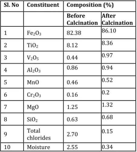
The typical compositions of iron oxide before and after calcinations are given in Table 1. The chemical/instrumental analysis of IOR indicated the presence of 82.38% Fe2O3, 8.12% TiO2, 1.25% MgO, 0.86% Al2O3, 0.63% SiO2 and 2.70% total chlorides. The predominant constituent in both the samples is iron oxide. Oxide constituents of V2O5, Cr2O3, and MnO are also found in the sample. It is clearly evident from the above table that the calcination at elevated temperature has diminished the chloride content thereby enriching the iron values in it.
Table -1: Typical Compositions of iron oxide before and after calcination at 500 oC
Sl. No Constituent Composition (%) Before subjected to heating at elevated temperatures is depicted in Fig. 1. The total chloride in the sample has been found to decrease with temperature. The volatile chlorides has released off from the iron oxide as seen from the values dropping to around 0.15% for IOC from 2.7% for IOR upon heating the sample at 500 oC which is a significant observation.
Fig -1: Total Chloride in iron oxide as a function of temeprature
© 2015, IRJET.NET- All Rights Reserved
Page 1495
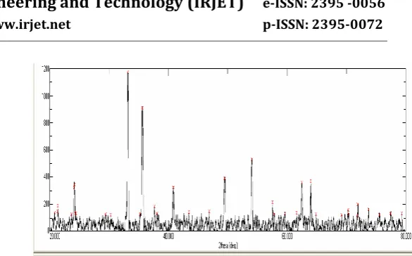
Fig -2: Variation in pH of iron oxide against temeprtaure.The XRD patterns of IOR and IOC samples are shown in Fig. 3a and 3b respectively. IOR sample showed strong peaks at 2θ22.40 and 29.70 and weak peaks at 2θ33.10 and 35.60 while calcined IOC demonstrated two strong peaks and four weak diffraction peaks at 2θ 33.10, 35.70, 24.10, 40.80, 49.40 and 54.10. The diffraction peaks appearing at 2θ29.70 and 35.60 could be attributed to Fe3O4 face-centered cubic structure. No drastic change in the diffraction pattern was observed after calcinations, but when minutely examined the sharpness of diffraction pattern at 2θ 35.60 was slightly increased to 35.70 possibly due to the increase in crystalline size upon calcination The peak at 33.10 can be ascribed by hematite phase of Fe2O3 [19]. New peaks are found to appear at 2θ24.10, 40.80, 49.40, and 54.10 and strengthening of the peak at 2θ33.10 and 35.60 for the calcined samples. The latter confirms the artifact of α-Fe2O3 crystallite. The diffraction peaks centered at 2θ 24.1, 33.1, 35.6, 40.8, 49.4, and 54.1 may be assigned to hexagonal rhomb-centric α-Fe2O3 (hematite) [19]. Hematite is an antiferromagmetic insulator with corundum structure in which Fe3+ ions are octahedrally coordinated by O2- ions which are organized in hexagonal structure [19]. All the above results suggests in addition to reduction of chloride content, that phase and structure of iron oxide can be tailored and direct transition from Fe3O4 (magnetite) to α-Fe2O3 (hematite) can be achieved as a result of calcination at elevated temperatures above 500 oC. The strong and sharp diffraction peak around 2θ 33.1 was employed to estimate the mean crystalline size of α-Fe2O3 using Debye-Scherer formula and found to be 197 nm.
Fig -3a: XRD pattern of noncalcined iron oxide.
Fig -3b: XRD pattern of Calcinediron oxide
Figs 4a and 4b reveal the morphology of the iron oxide sample (IOC) calcined at 550 oC by SEM and TEM observations respectively. In the SEM image, one may clearly observe the particles with irregular shapes and size. The particle size of the calcined samples varied between 100 nm to more than 200 nm as revealed from TEM which supports the results of XRD. Iron oxide grains are present in different shapes like round, sub-round, lath, prismatic etc and look brittle in nature. Some particles are partially fractured and shattered. The TEM image also exhibits weak aggregation of particles indicating development of super paramagnetic structure.
© 2015, IRJET.NET- All Rights Reserved
Page 1496
Fig -4(b): TEM image of calcined iron oxideIn the context of the results of above studies, a process is proposed for executing the calcination process for reduction of iron oxide to lower levels. Fig. 5 illustrates the flow sheet of the recommended process consisting of operations such as filtration, calcination, cooling etc. Facilities to recover the fines likely to be emanated during calcination and scrubbing the harmful emissions are also included in the system.
4. CONCLUSIONS
Calcination at elevated temperature has been successfully employed to reduce the chloride content in iron oxide generated during acid regeneration of spent hydrochloric acid (produced by benelite process), to significant levels, thereby possibly enabling the iron oxide suitable for a variety of applications. The acidity level of the iron oxide has also been significantly reduced as a result of removal of significant chlorides through calcination. The diffraction pattern reveals the direct transition of magnetite to α-hematite upon calcination. The changes in morphology upon calcining the iron oxide have also been studied in detail. According to the results, a process for calcinations and recovery of iron oxide has also been presented. This approach will allow interested parties to evaluate the advantages and further utilize the value-added iron oxide in their process. However the practical utility of the process requires full optimization of various process parameters and also economic assessment of the process.
Fig -5: System proposed for implementaing the calcination process
SCRUBBER
CALCINATION AT 5500
BAG FILTER
BAGGING (iron oxide powder with low chloride)
COOLER
POND SLURRYING
TANK
FILTRATION
CYCLONE
Dry iron oxide powd er Lime
Slurry
H2O
High Chloride,low ph
Iron oxide sludge
© 2015, IRJET.NET- All Rights Reserved
Page 1497
ACKNOWLEDGEMENT
The authors sincerely thank, Mr. C.J George (Executive Director, KMML, India), Mr. Suresh Kumar (Technical Advisor to MD, KMML, India) and Dr. S.Harish Kumar (Head of Department of Chemical Engineering, Manipal Institute of Technology, India) for providing the opportunity and support.
REFERENCES
[1] S.A.Berkovich, “Recovery of titanium dioxide from ores”, US Patent, 3903239 Ontario Research Foundation, I975.
[2] J.H.Chen, “Beneficiation of ilmenite ore”, US Patent,
4019898 Benelite Corporation of America, 1977.
[3] A.J.Morris, “Process for producing titanium tetrachloride”, US Patent, 4435365 Kerr-McGee, 1982. [4] B.T.Judd, “Titanium dioxide production from ilmenite”, Euro Patent, 0186370 Grampian Mining Company Ltd, 1986.
[5] M.J.Hollit, “Production of synthetic rutile”, US Patent,
5427749 Wimmera Industrial Minerals Pvt. Ltd, 1995.
[6] G.F.Balderson, “Method for the production of synthetic rutile”, US Patent, 5885324 Tiomin Resources Inc, 1999.
[7] W.P.C.Duyvesteyn, “Processing of titaniferous ore to titanium dioxide pigment”, US Patent, 6375923 Altair Nanomaterials Inc., 2002.
[8] M.H.H.Mehampoud, A.A.L.Afifi and I.A.Ibrahim, “Reduclive leaching of ilmenite ore in hydrochloric acid for preparation of synthetic rutile”,
Hydrometallury.,vol. 73, pp. 99-109, 2004.
[9] F.Islam and Z.Kawnin , “Separation and recovery of titanium from iron bearing leach liquors by solvent extraction with di-(2-ethylhexyl (-phosphoric acid-tributylphosphate-thiocyanate system: I”, Bangladesh
J Sci Res., vol. Xll , pp. 83-89,1978.
[10]E.Narita, H.Takeuchi, H.lchikawa, T.Odagawa and T.Okabe, “Manufacture of the pure titanium (IV) oxide by the chloride process. ll. Selective extraction of titanium (IV) and iron(lll) from hydrochloric acid leach liquor of ilmenite ore by tributyl phosphate”,
Bull Chem Soc Jpn.,vol. 56, pp. 1832-1836,1983
[11]K.M.Allal, D,Hauchard, M.Stambouli, D.Pareau and G.Durrand, “Solvent extraction of titanium by tributylphosphate, trioctylphosphine oxide and decanol from chloride media”, Hydrometallurgy.,vol. 45, pp. 113-128,1997.
[12]J.Saji and M.L.P.Reddy, “Liquid-liquid extraction separation of iron(lll) from titania wastes using TBP-MlBK mixed solvent system”, Hydromelallurgy,.vol 61, pp. 81-87,2001.
[13]M.L.P.Reddy and J.Saji, “Solvent extraction of tetravalent titanium with organophosphorus extractants”, Mineral Processing and Extractive
Metallurgy Review,vol 23 , pp. 199-227,2002.
[14]G.Auer, “Method of producing iron oxide pigments from waste acid resulting from TiO2 production”, US
Patent, 6530987 Bayer Aktiengesellschat, 2003.
[15]P.N.Remya and M.L.P.Reddy, “Solvent extraction separation of titanium(IV), vanadium(V) and iron(lll) from simulated waste chloride liquors of titanium minerals processing industry by the trialkylphosphine oxide cyanex 923”, J ChemTechnol
Biotechnol, vol 79 , pp. 734-741,2004.
[16]O.Moklebust, “Regenerating HCl from iron chloride solutions”, US Patent 13529931 National Lead Co., 1970.
[17]E.A.Walpole, “Acid regeneration”, US Patent
5635152Austpac Gold NL, 1997.
[18]A.Lebl, “Process for the extraction and regeneration of acids from spent acids”, US Patent 6214310 Andritz- patentverwaltungs-gesellschaft, 2001. [19] Surender Duhan and Sunita Devi, “Synthesis and
Structural Characterization of Iron Oxide –silica Nanocomposites Prepared by the Solgel method”, International Journal Of Electronics Engineering,. vol. 2, pp. 89-92,2010.
BIOGRAPHIES
Irfana Shajahan , pursuing her M.Tech in Chemical Engineering at Manipal Institute Of Technology ,Karnataka,India. She has special interest in topics related to nanotechnology.
Dr. John George has over eight years of experience in the field of Titanium Dioxide Pigments. He has been working as a Scientific Officer at ‘The Kerala Minerals and Metals Limited (KMML)’, Kollam, India since 2005. He specializes in new product development and product improvements in the Department of Research and Development. He has over ten publications in journals of international repute to his credit.
© 2015, IRJET.NET- All Rights Reserved
Page 1498
international repute. He hasworked in TiO2 manufacturing industry (Travancore Titanium Products Ltd, Trivandrum) for 2 years.