The Effect of the tool rotational speed, plunging speed and tool progressive speed on
the Defects during Friction Stir Processing on AZ91
H. Amini 1, N. Ab2*, M. Hopour 2
1-Ph.D. Student, Mechanical Engineering, Shahid Rajaee Teacher Training University, Tehran, Iran 2-Assoc. Prof., Mechanical Engineering, Shahid Rajaee Teacher Training University, Tehran, Iran
Abstract
In recent years, Magnesium alloys, because of good tensile strength at room temperature, good dimensional stability, high damping capacity, good machinability, the potential to reduce the mass of vehicles, and cast ability, has attracted a lot of attention. However, due to poor formability and creep resistance above 100 C, because of the presence of unstable β-Mg17 Al12 phases on the grain boundaries, the usage of Mg
alloys was limited. To solve this problem, the high strain rate deformation processes such as friction stir processing (FSP) can be performed on Mg alloys to modify the microstructure and crush the secondary phases. This process, with decreasing the grain size and increasing the solute concentration, lowered the creep rate and improved the mechanical properties. However, to improve the properties, it is essential that the process parameters are selected correctly and since the performing process is very costly and time consuming, it is recommended to use the numerical methods to determine the appropriate parameters. In the present paper، a three dimensional finite element method based on ABAQUS software is prepared to study the effect of the rotational speed, plunging speed and progressive speed on the formation of process defects during FSP on AZ91. The results show that the model can be used as a tool to prevent the formation of process defects.
Keywords: (Mg) alloys, friction stir processing (FSP), AZ91, defects, flash, and groove.
Introduction
Friction stir processing is a new kind of metal working process where a rotating tool with pin and shoulder is plunged into magnesium workpiece. A localized modification in the microstructure of slightly more than the pin size area is achieved [1]. The tool traverse along the length of the workpiece to be processed with a fixed rotational speed, due to which, severe plastic deformation takes place and the material flows from the front end of the pin to the rear end of the pin. Very fine grain size microstructure is evolved due to recrystallization at the stir zone. The important parameters in controlling the formation of the stir zone are the axial force, rotational speed and tool dimensions.
The elimination of friction stir processed defects are important in order to improve the quality of the friction processed zone[3].However the information available in the existing literature are not much helpful to understand the reasons for defect formation as well for its elimination when process parameters are altered. Hence, in this experimental investigation a study has been carried out to produce defect free processing zone by varying the process conditions.
In recent years, many researchers used the numerical model to study the FSP. Some studies used the numerical model to investigate the formation of defects during the FSW process. Also, Marker material method has been used to study the flow of material [1]. The insufficient setting of the process parameters during performing FSW on AA6061 alloy caused the formation of the hook defects [2]. Ajri and Shin [3] used the 3D models to prevent the formation of the excess flash, tunnel defects, hook defects, and cavities [4]. The results
show that the pin appearance (including the height and diameter) and the angle between pin end and workpiece (tool tilt) are the most effective parameters for the eliminating defects. “The material flow and thermal cycle influence the hook defect in the joint interface during the FSW process” [5]. Mohammad Ali Ansari et al., [6] shows that the numerical modeling is a sufficient method to study this process and adjust the optimum process parameters. Sato et al. performed FSP on AZ91 magnesium alloy and observed its effect on microstructure grain refinement and homogenization as compare to as-cast properties of magnesium alloy [6]. Zhang et al.examined the microstructure and the mechanical properties of FSW of 2219-T6 under submerging conditions. They observed that increasing the rotational speed above 1400 rpm caused void defect to form in the stir zone. Increase in grain size and in dislocation density in the stir zone was observed with increase in the rotational speed [7].
Defects
The material transport in the FSP was regarded as a laminar, viscous and non-Newtonian liquid flow during passing the pin. The results of the simulation showed that the material flows vertically. In the retreating side, the material is pushed up and in the advancing side the material is pushed down.
Since the friction stir processing is performed in the solid state and no melting or freezing, takes place in the stirring zone, therefore, the common defects that observed during the traditional welding processes such as the cavities, hot cracks and freezing cracks are not formed during this method. However, it is possible to create the specific defects that only related to this method, if the tool design and welding parameters are not suitable. Normally the defects depending on the FSP conditions, are cavity (caused by the abnormal stirring), tunnel, voids, and flash (due to the excess heat input), groove and cracks (caused by insufficient heat input). The Defects Removal are essential to improve the quality of the processed workpiece. In this research, a study has been carried out to produce the defect-free workpiece by varying the process speeds.
However, few previous experimental and numerical studies focused on forming mechanisms on Friction Stir Processed defects and the FSP defect types were often detected by means of conventional microstructure examinations such as non-destructive testing techniques. Non-destructive testing (NDT), methods including radiography testing and fluorescent penetrating fluid inspection, which based on techniques that rely on the application of physical principles to determine the characteristics of materials, always contributes to detect and assess flaws or harmful defects without changing the serviceability or usefulness of workpieces. NDT plays a crucial role in industrial fields, especially on aerospace, automotive, railway, power generation, ship structure and petrochemical pressure tanks. Certainly, NDT methods can also be applied in the quality control of friction stir processed work piece, adjusting the process parameters to eliminate any detected defects and determining the existence locations.
The FSP defect types, such as tunnel, void, porosity, defective tightness, surface groove, excessive flash, ‘Z-curve’,
‘kissing-bond’ and crack-like root-flaw, are quite different from conventional fusion welding and casting flaws. Here, the following three different types of defects are studied: (1) A large mass of flash due to the excess heat input; (2) Cavity or groove-like defect caused by an insufficient heat input;
(3) Cavity produced by the abnormal stirring.
Another common defects during the FSP process is pin breakage. When the pin doesn`t break, the effect of pin at the end of the process should be empty. If the end hole is filled, it indicates that the pin is broken during the process and no mixing has occurred. The pin breaks in two states. The pin breaks inside the workpiece and tool move until the end of the path. The pin breaks and the broken piece reaches the surface of the workpiece
The tunnel, porosity, void flashes
According to previous discussion about FSW defects formation mechanism, the inner material-loss defect type is characterized by excessive metal loss of work-piece during FSW. Material-loss defects include tunnel, porosity, void and flash. The main cause for the inner material-loss defect occurring is that insufficient material cannot instantaneously fill the cavity remaining after the rotating FSW tool travels. During the plastic material transfer, if the resistance against material flowing to the tool trailing edge is too high, the fill material will be transformed to excessive flash defect on both sides of welds. By the condition that constant volume remains in plastic deformation process, a total mass flux of plastic deformed material during the whole FSW process maintains balanced. Fig. 11 illustrates the primary parts of total material volumes during FSW. Vflash denotes the volume of flash defects material volume. Vvoid denotes the inner material-loss defects including tunnels, porosity, and larger voids within welds. Vkey-hole is the volume of the remained keyhole after welding, which is also approximately equal to volume of the tool-pin. As illustrated in Fig. 11, Vcollapse is caused by the oolshoulder down force on the work-piece. The simple volume conservation relationship is given as Eq. (1). Vcollapse and Vkey-hole can be calculated using weld geometric parameters simply. After milling the excessive flash material off, the Vflash can be roughly measured by displacement of water. When the empirical criterion factor C, given in Eq. (2), is much larger than zero, the material inner-loss defects should exist within welds.
The effect of speeds on formation of DEFECTS
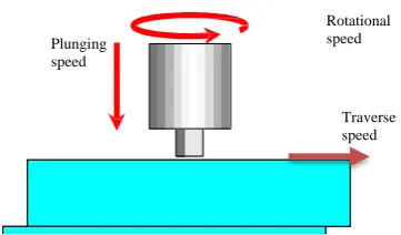
When the traverse speed becomes higher, the rotating speed must also be increased to avoid any possible welding defects such as voids. Simultaneously increasing the rotation and translating speeds of the welding tool can lead to an increase in the residual stress. A similar approach can be used to investigate fracture mechanics-based approaches to the prediction of skin-stiffener separation. A 3D localized FE model was developed to predict likely conditions that could result in the generation of defects during FSW.
Fig. 1: The rotational, plunging and traverse speeds
According to the previous study, materials near the rotational tool probe can be divided into three regions, i.e. rotation layer, transition layer, and deflection zone, Schmidt et al. (2006). During FSW process, materials in these three regions present severe plastic deformation and flow with the rotation of the tool probe. Materials in advancing sides tend to flow forward of the tool probe, but, on the contrary, materials in retreating side tend to flow backward. On the other hand, material flow is asymmetric in advancing side and retreating side. Therefore, it can be considered that, during FSP, the cavities form preliminary in AS, and immediately, flowing materials in other regions fill these cavities to form a sound weld. If the full filament is insufficient or lagging, these cavities will remain inner the weld. As a result, when the processing has finished, a tunnel defect forms inner the workpiece and distributes through longitudinal direction of the process path. In the friction stir processed workpiece, some defects are very sensitive to small variations in some process parameters. In order for validating the numerical model preparing to simulate FSP and to contribute this process to the industrial consolidation, the experimental implementation results need to be supported by a reliable, Non-Destructive Testing (NDT) system.
.
The experimental
The base material used in the present investigation was commercially available AZ91. A milling machine with maximum spindle speed of 2260 rpm and motor capacity 3 HP is used for friction stir processing. The tool was prepared with pin size of 6mm diameter and 3mm length and the shoulder diameter 18mm. The shoulder is flat and tool tilt angle is 3 degree. The traverse speeds is 60mm/min, 110mm/min and 166mm/min and rotational speed are . The penetration depth was kept constant at 1025 rpm. A suitable fixture was designed and fabricated for processing the samples. Specimens were prepared by cleaning with acetone before processing. Figure 1 shows a typical setup for friction stir processing.
Specimens for characterization of tunnel defects were prepared by mechanical polishing and then investigate using
Rotational speed Plunging
speed
optical microscope. EBSD samples were prepared by mechanical polishing and then electro polishing. EBSD was performed using FE-SEM fitted with TSL-OIM acquisition software.The numerical modeling
In this paper, the workpiece was modeled as a deformable body and was meshed with 3D8RT elements. The chemical composition of this alloy is shown in Table 1. Also, the physical and mechanical properties of AZ91 is shown in Table 2. The elastic-plastic Johnson-cook material law is used to model the temperature and hardening dependent behavior of material according to the Eq. (1).The material/process constants, A, B, C, n and m, in this model is shown in table 3.
(1)
Where σ is the equivalent stress, ε is the equivalent plastic strain, ε` is the plastic strain rate, ε`0is the reference strain
rate,
T
0 is the room temperature,T
melt is the melting temperature,A
is the initial yield stress (MPa),B
is the hardening modulus,n
is the work-hardening exponent,C
is the coefficient dependent on the strain rate andm
is the thermal softening coefficient.Table 1: The chemical combination of the AZ91
Mg … other Mn
Zn Al
Bal 0 2 / 0 19 / 0 68 / 0 79 / 8
Table 2: The Material properties of AZ91
The properties of AZ91 Value
“Young`s modulus of elasticity (GPa)” 46
“Poisson`s Ratio” 0.33
“Thermal Conductivity (W/mK)” 72
“Coefficient of Thermal Expansion
(0C-1)” 2.5*10-5
Density (g/cm3) 1.81
Specific Heat Capacity (J/Kg 0C) 1050
Solidus(0C) 470
Liquids (0C) 582
Table 3: The Johnson-Cook constants to define the behavior of AZ91. [7]
“parameters Value
A 108
B 737
C 0.06180
n 0.636
m 2.551”
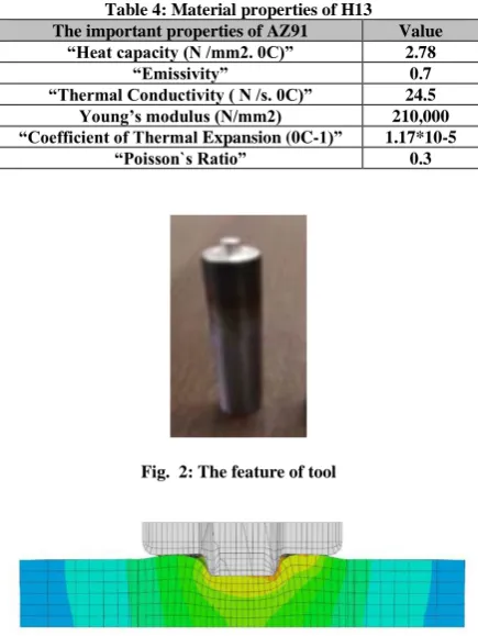
Tool steel H13 was used to make the tool. The tool modeled as a deformable body and meshed with 3D8RT elements. The chemical composition of H13 and the important properties of H13 is shown in tables 4 and 5. The pin of tool was prepared with 6mm diameter and 3mm length. The shoulder diameter is 18mm, also, the shoulder is flat and tool tilt angle is 3 degree. The feature of tool, is shown in Fig. 2.
Its main features are an Arbitrary Lagrangian Eulerian (ALE) formulation and an adaptive remeshing procedure based on error estimation. A 3D FSW simulation based on friction models calibration was presented using Eulerian and ALE formulation.
Table 4: Material properties of H13
The important properties of AZ91 Value
“Heat capacity (N /mm2. 0C)” 2.78
“Emissivity” 0.7
“Thermal Conductivity ( N /s. 0C)” 24.5
Young’s modulus (N/mm2) 210,000
“Coefficient of Thermal Expansion (0C-1)” 1.17*10-5
“Poisson`s Ratio” 0.3
Fig. 2: The feature of tool
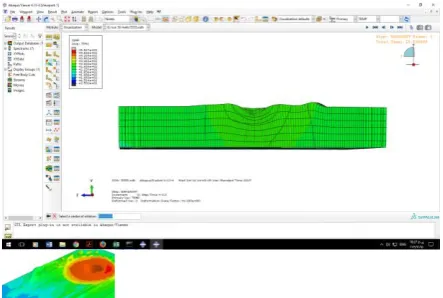
Fig. 3: The processed zone and tool
The processed zone and tool is shown in Fig. 3. Also, the experimental set up is shown in Fig. 4. The FSP process started by inserting the rotational pin into the workpiece until the tool shoulder touched the surface of workpiece. Then the tool was moved with a constant traverse speed while the tool rotated. The initial temperature of the tool and workpiece was 25 °C. Here, ALE technique along with adaptive remeshing option and fully coupled temperature-displacement analysis, is used to model this process. In this model, at every time increment, the temperature and displacement for all nodes are calculated. The critical issue of simulation is modeling the contact condition between the tool and workpiece. The heat transfer through the bottom surface of workpiece is controlled by the coefficient of 1000 W/m2 K. The heat convection coefficient on the surface of the work piece are h=12 W/m2K with ambient temperature (25 0C). A constant
friction coefficient of 0.3 is assumed between the tool and workpiece for penalty contact method. After performing FSP, the process defects investigated.
Fig. 4: the diagram of friction stir proceesing
Experimental
speeds. The specimens investigated for the observation of the defects specially the grooves, flashes and pin breaks. Also, the small defects on the surface of can be traced through the penetrating fluids method. The following picture is an example of the leakage of permeable fluids from the tunneling defects on the surface of the processed workpiece as shown in Fig. 5. The internal defects can be investigated through the radiography method. The Fig. 6 showed the pin breakage during FSP.
Fig. 5: the defects that traced with PT test
Fig. 6: the usage of RT test for observation the defects
The workpiece experiences the temperature above 400 0C
when the tool rotates at very high speeds. The generated heat softens the material near the tool and high tool shoulder pressure ejects the excessive amount of material as the flash. Kim et al. [42] reported that excess heat input caused by low progressive speed or high rotational speed lead to the formation of flash. In Fig. 7, the formation of flash during MP-FSP was shown.
Results and Discussion
The quality of workpieces after friction stir processing is affected by various defects produced during the processing. A FEM simulation was developed and verified by the experimental results. The tool rotational, plunging and progressive speed can be predict to prevent the formation of the defects. A good agreement between simulation and experimental results was seen.
In order to make FSP more reliable and practical, it is important to develop modeling for predicting the optimum condition. It is generally believed that nonlinear ultrasonic testing would be a useful technique to detect and estimate the size of both planar and volumetric defects. The properties of FSW joints can be characterized using optical micrographs,
X-ray diffraction. The shape, size, and distribution of defects are depended to the speeds.
Fig. 9: the observation the flash in numerical model
The cracks are formed during friction stir processing beneath the tool shoulder where the maximum temperature occurred. Peak temperature was observed at the edge of the tool shoulder where liquation crack happened. The process parameters play important role in producing defect-free workpiece during friction stir processing. This defects can be observed due to the low progressive speed or high rotational speed and not-enough shoulder pressure. The cracks is shown in Fig. 10.
Fig. 10: The cracks are formed during friction stir processing
The peak temperature when the traverse speed is 50 mm/min, at point with 6 mm distance from center of the SZ is 181 ºC (Fig. 2b). However, increasing the traverse speed to 63 mm/min, causes the peak temperature to drop to 141 ºC which leads to formation of the tunnel defects on the friction zone as it is show in Fig. 3. At traverse speeds, up to 40 mm/min (by the rotational speed of 710 rpm) the amount of heat resulted from plastic deformation and friction is not enough to flow the materials. This inadequately soft material cannot flow properly over the tool pin and merge completely at behind. Thus, cracks and cavities emerge on the processing zone. Therefore, it is quite to produce a defect-free specimen with the traverse speeds up to 40 mm/min, where the rotational speed is 710 rpm.
The friction stir processed workpiece are disposed to other defects like tunnel defect, cracks, pinhole, piping defect, kissing bond, etc. due to unsuitable flow of metal and inadequate consolidation of metal in the FSW region, Elangovan and Balasubramanian (2007). As revealed in Fig. 2, five types of defects can be observed from the overall crosssectioned samples. First, tunnel defects can be found in all of the samples that created with cylindrical and triangle tools. Second, kissing bond and zigzag defects can be found in joints that created with cylindrical tool. Third, crack and OJLwSPD defects can be found in the advancing side.
If the plastic deformed material-flow from the retreating side is not enough to fill the cavity absolutely and instantaneously before cooling to still-state, the tunnel defects will remain without hydrostatic pressure.
Fig. 12: the groove formed during FSP
Concluding Remarks
During FSP, materials has been stirred and jointed below their melting point TM. Therefore, no large-scale or obvious liquid state exists within friction stir processing. During friction stir processing, material flow or mixing does not occur at the atomic level and the mass transfer or viscoelastic material-flow migration during FSW is asymmetrical between the retreating side (RS) and the advancing side (AS). Also, the material migration behavior along the work-piece thickness direction, largely depends on the geometric design of the tool-pin and processing parameters. If FSP is not carried out under appropriate processing conditions, various defects will form in processed zone and the affected zone.
During the FSP process, several macro-defects like the porosity, grooves, cracks, voids, and tunnels, etc., are possibly generated due to insufficient material flow or excess or not enough heat input mainly influenced by rotational
[1 ] Grujicic M, Arakere G, Pandurangan B, Ochterbeck JM, Yen CF, Cheeseman BA, Reynolds AP, Sutton MA (2012) Computational analysis of material flow during friction stir welding of AA5059 aluminum alloys. J Mater Eng Perform 21(9):1824–1840
[2]Cao JY, Wang M, Kong L, Yin YH, Guo LJ (2017) Numerical modeling and experimental investigation of material flow in friction spot welding of Al 6061-T6. Int J Adv Manuf Technol 89(5–8): 2129–2139
[3] Ajri A, Shin YC (2017) Investigation on the effects of process parameters on defect formation in friction stir welded samples via predictive numerical modeling and experiments. J Manuf Sci Eng 139(11):111009
[4] Chauhan P, Jain R, Pal SK, Singh SB (2018)Modeling of defects in friction stir welding using coupled Eulerian and
speed (ω) and travel speed (υ). The results show that higher tool rotational speeds generate larger heat, which results in more thermal stress during cooling process, while lower tool rotational speeds lead to insufficient material flow .Thus, processed workpiece without defects are only formed at optimum rotational, plunging and traverse speeds.
The most common defect in this process is the flash. The flash occurs due to high heat and excess pressure. The defect, is generated with high rotational speeds and low progressive speeds. Also, excessive pressure is the most important factor contributing to this defect.
The cracks, grooves, and tunnel defects are another common defects in the process. The Tunnel defect occurs because of low input heat (low rotational speed and high progressive velocities) and due to insufficient mixing. It has also been observed that groove occur at high process speeds and low force forging. Generally, there are two types of tunneling and groove defects that generated due to low inlet heat (type 1) and insufficient mixing (type 2). The appearance of the mixing zone in the sample due to low inlet heat (type 1) is similar to that of the free-defect sample, but the appearance of the mixing zone in the sample having tunneling defect due to insufficient mixing (type 2) is quite distinct and flawed. They also believe that the size of the tunnel defects caused by the low heat input (type 1) decreases with increasing vertical force during processing. However, the increase in forging force causes a slight decrease in the size of the tunneling defect caused by insufficient mixing (type 2).
The surface quality of the FSPed specimen at rotational and traverse speeds of 1400 rpm and 80 mm/min, respectively, is acceptable and no defects are seen on the cross section. In this specimen, the peak temperature was 208 ºC. However, by increasing the traverse speed to 100 mm/min, surface quality is acceptable (Fig. 4). In this situation, the detected peak temperature decreased to 179 ºC.
10 mm thickness AZ91 alloy plate was used as base material. The welding and rotation speeds were 63 mm min- 1 and 1600 rpm, respectively. The microstructure of the specimens was studied by using optical (OM).
References
Lagrangian method. J Manuf Process 34(November
2017):158–166
[5] Chu Q, Yang XW, Li WY, Vairis A, Wang WB (2018) Numerical analysis of material flow in the probeless friction stir spot welding based on coupled Eulerian-Lagrangian approach. J Manuf Process 36(July):181–187.
[6] Mohammad Ali Ansari1 & Avik Samanta2 & Reza Abdi Behnagh3 & Hongtao Ding2, An efficient coupled Eulerian-Lagrangian finite element model, 2018.