U N I V A C
·
S O L I D - S T A T E
90
CONTENTS
INTRODUCTION ... 1
90-COLUMN PUNCHED-CARD CODE ... 2
HIGH-SPEE D READER 4 General Description . .... ... .... ... ... .... ... .... ... ... ... ... ... ...•... ..• 4
Input Logic •.. ... .... ... ... ... ... ... ... ... ... .•... ... ... ... 4
Card Words ... 7
Timing Mechanism ... ~... ... 10
Programming the Operation Cycle ... ... 11
Input Checking Routine ... 15
Error Conditions ... 15
Efficient Utilization of the High-Speed Reader ... 16
READ-PUNCH UNIT ... 19
General Description . ... ... 19
Input-Output Logic ... 20
Card Words ... 23
Programming the Operation Cycle ...• ~. ... 2·5 Modes of Operation ...•... 29
Program Checking ... ... ... 30
Error Conditions . ... .... ... ... .... .... .... ... ... ... ... ... .•.... ... .... ... 31
HIGH-SPE ED PRrNTER ... 33
General Description ... , ... ... 33
Output Logic ..•... ... ... ... ... ... ... ... ... ... ... ...• 33
Print Mechanism ... 35
P.rogramming the Operation Cycle ... 37
Error Conditions ... ... ... .... ... .... ... .... ... ... ... ... 40
STOP SUB-ROUTINES 43 General Description ... .... ... ... ... ... ... ...• 43
Contents of the Stop Routine ... ... ... ... 43
This manual is a reference ;n writing input and output
program routines for the Remington Rand UNIVAC
Sol id-State 90. It contains basic and detailed functional
descriptions of the HIGH·SPEED READER,
READ-PUNCH UNIT, HIGH·S PEED PRINTER and the program instructions which control these units. An explanation
of the Remington Rand 90-column punched-card code,
an important programming prerequisite, and the buffer
system and inpuVoutput logic of each unit is also
in-cluded. The complete program instruction repertoire,
programOming techniques, and other detailed
programm-ing information is contained in separate publications.
gO-COLUMN PUNCHED-CARD CODE
GENERAL DESCRIPTION
The Remington Rand punched-card, Figure 1, is composed of an Upper Field (UF) and a Lower Field (LF). Because there are 45 punch columns in each of the two fields, the Remington Rand card is referred to as a 90-column card. The col-umns comprising the Upper Field are numbered one through 45; the Lower Field columns are numbered 46 through 90.
NUMERICS ALPHABETICS
/
•
0 1 2 3 4 5 6 7 8 9 A B• ••
C 0 E F G H I J K L•••
M N 0 P Q II 5 T•
U•••
V W x y z"
u 'i-'z-'Z--'i-.,,-'i-'z--'Z-';-iz-.'i-iz-'z-• • -'Z--'i-'Z-.ii-'z--'i-.-'i-'z-'z--,z-.-"'i-".-Iz--ii-'i-G-'z.'z-'z-ii-1z--ii-'z
i 3. 3. 1, 1, 1, J • • • J. J. J. J. J.
'.
J. '. J, • • 1. J • • • • • 1. 1, 1, • • • 1, J • • l, • • 1, . 1 , 1, 1. J. I, I,S6 56 S.
'.
I. '.'.
'...
";''.
'...
".'.
'..
'....
,;...
""."."."
" '6 '6." '6 '6 '6 '6c.
'.
78 7. '8'.
'8 7. '8 78 • • 78 78 78 78." ' • • • • 78 78 78 78 '8 7, '8 • • • • • • 78 • • 7, • 7. 7, 7, 7. 78, , ,
.
,..
,...
"...
" ",.
I,A21" " "
...
" . "..
" " "....
"...
"..
..
..
0
$ # /
.
+ II.. I ( )z ~ :
..
;••••
a:
••
•••
z
0
~ .-!~ ,~ -•.• ' ~ -•. .- .-• • -• ..-' z--.': -,~--,:;-';-,i-'~ -G -,z-,~--'i -'i -'i-'1 -'2-' ~ -IZ--'~-'i-'z--11-'2--I:;-'2--'-2-'2-'2--'2-';-'i-':
~
....
"."
"." ••• " .3, 3. 1,'.
1. 3, 1.'.
'.
" J,'.
1. 1. 1. 1. 3. 1. 1. 1. 1. 1.'.
'.
1. ]4 ]4 1. 1.'.
.,(
<Ii '
...
'...
'...
'. '.
'.
'.
I.'. '.
s. '0'.
'.
s.'.
'.
'. '6'.
'6'.
'.
'.
'.
"'.
'. '.
'.
'.
'. '.
"
-; . ' , . " • • '8 '8 • • 7 • • • • • ·8 7. '8 7. 78 78 7. 7. 7,
.
• 7. 7. '8 78 '8 78 78 78 "
'.
'. '.
' . 78 7. 78 78 78 '8 ~~ • • oJ • • • • •
•••••••
• •• •
••
• • • • •• •
• • • • • • • • • • • • • • •• •
It 46 . , . . . , so !II 52
" "
.. ..
"..
"..
" ".. ..
.. ..
.,
.. ..
,. " " " "...
"..
, . • II..
U..
..
..
.,
_-"-00SPECIAL CHARACTERS
Figure I Remington Rand Punched Card and Card Code
0 1-1 3 5 7 9 1_ 0 1-1 3 5 7 9 1-UPPER FIELD UF LOWER FIELD LF
Both the Upper and Lower Fields contain six rows numbered: 0, 1, 3, 5, 7, and
9. These numbers are called the card row punch positions. There are a total
of 540 punch positions in each Remington Rand 90-column punched-card (45 columns
per field X 6 card row positions per column X 2 fields
=
540 punch positions).NUMERIC REPRESENTATION
Zero and odd decimal values are represented in 90-column card code by a single
punch in the appropriate card row punch position of a column. Zero, for example,
is represented by a punch in the 0 punch position of a column (See column 4, Figure 1). Three is represented by a single punch in the 3 position of a column, five by a single punch in the 5 position of a column, and so on.
Even decimal numbers are represented by punches in two card row positions of
a column. One of the punches is always in the 9 row position, the other is in
Because the 1, 3, 5, 7, and 9 row punch positions are used to indicate odd or even decimal values, depending upon whether a punch is present in the 9 row punch position, each individual punch position in a 90-column card is marked
(12, 34, 561 etc) to indicate the complete potential of each punch position.
ALPHABETIC REPRESENTATION
Alphabetics are represented by varying combinations of two and three punches in
a particular card column. Figure 1 contains the 90-column card punch codes for
each of the 26 characters of the alphabet.
SPECIAL CHARACTER REPRESENTATION
Special characters are represented in 90-column card code by varying combinations
of from two to five punches in a card column. Figure 1 contains the punch codes
HIGH-SPEED READER
G~~ERAL DESCRIPTION
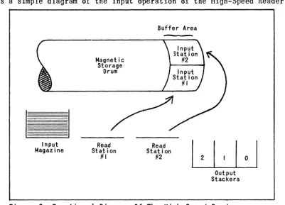
The High-Speed Reader is the major input source of the UNIVAC Solid-State 90. It reads information punched into 90-column cards at speeds of up to 450 cards per minute. The High-Speed Reader is composed basically of an input magazine, two card read stations (Read 1 and Read 2) and three output card stackers. The input magazine will contain up to 1000 cards; each of the three output stackers will contain as many as 1200 cards.
An input card is read at the Read 1 and is transported to Read 2 where it is read again. The information read at both read stations is transferred to a special area on the storage drum (Central Processor) called the card buffer. From the card buffer, the information is transferred into the main storage area of the drum where it is available for use according to the program. Figure 2 provides a simple diagram of the input operation of the High-Speed Reader.
Input Magazine
Magnetic Storage
Drum
Read Station
~I
Buffer Area
Read Station
~2
Output Stackers
Figure 2 Functional Diagram Of The High-Speed Reader
INPUT LOGIC
Data cards entering the UNIVAC Solid-State 90 from either input unit normally
contain information recorded in 6-bit Remington Rand card code. (Input cards
may contain information recorded in 4-bit binary code of the computer). Fig-ure 1 shows the 51 alphabetic, numeric, and special characters that may be punched in 90-column card code.
Fig-Card Sensing
Card Row Binary
Positions Representation
o I 0 0 0 0 0 0 0 0 0 1 0 1 I 0 0 0 0 0 0 0 3 0 0 0 1 100 000 5 0 0 0 0 0 I I 000 7 0 0 0 0 0 0 0 I I 0 9 0 0 I 0 I 0 I 0 I I
Decimal
=
0 I 2 3 ~ 5 6 7 8 9 ValueFigure 3 Numeric Card Code
Under control of a program instruction (72), a card is transported from the
in-put magazine into the roller mechanism of the Reader. Once the card movement is
initiated, the card is automatically read at Read 1, then at Read 2, and finally is segregated into one of the output stackers. Read 2 enables the programmer to program comparisons with Read 1 to assure complete data identity and validity.
Normally, cards are fed continuously through the High~Speed Reader so that
cards are being read simultaneously at Read 1 and Read 2. Each row of a card is read as the card moves under the 45 brushes at each read station. The first row read consists of the least significant bits of all digits in the Upper
Field of the card; the next row read consists of the next higher-order bits, and so on. Therefore, six rows of a card must be sensed before complete characters are read.
After the six rows of the Upper Field have been read, the 45 brushes sense the six rows of the Lower Field.
Each time a card row passes under the read brushes, a pulse is placed on a roller beneath the card. Each brush which has a hole under it at the time the roller is pulsed receives a pulse from the roller. This pulse is equivalent to a binary 1 bit. Each brush which does not have a hole under it is insulated from the charged roller by the card. The insulation prevents a pulse from being placed on the brush. This lack of a pulse is equivalent to a binary 0 bit for that punch position.
Stacker Selection
Capacitor Storage
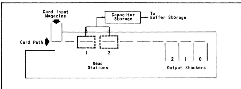
Information read at Read 1 and Read 2 is first sent to a temporary storage called capacitor storage (Figure 4), Capacitor storage is capable of storing one row
from the Read 1 and one row from the Read 2. Before the next card rows are read
at both read stations, the information in capacitor storage is recorded in a special area of the magnetic storage drum called buffer storage.
Card Input
Magazine
...
~ CapacitorI
l Storage,
,
r.L-,
r-J.--
i- 1 - - 1 1 - - 1 - -
L ___
JL ____
l
Card p a t h .
-I 2
Read Stations
To
. Buffer Storage
2
o
Output Stackers
Figure q Functional Diagram of Card Movement in High-Speed Reader
Card Buffer Storage
The card buffer band on the magnetic storage drum is used to store information temporarily during input-output operations. As an intermediate storage between capacitor storage and main data storage, the card buffer band is necessary be-cause of the difference in operating speeds of the relatively slow input-output units and the faster operating Central Processor. It also provides a storage area in which to assemble into complete words the information read row-by-row from the cards.
The card buffer storage band is used by both the High-Speed Reader and the Read-Punch Unit. Although it is not part of main storage, the card buffer con-tains 200 word locations, the same as any of the 25 main storage bands. Loca-tions 000-099 serve the High-Speed Reader; locaLoca-tions 100-199 serve the
Read-Punch Unit. (Only those operations concerning the High-Speed Reader portion of
While information being read at Read 1 and Read 2 of the High-Speed Reader is being recorded in buffer storage, the Central Processor is free to execute other instructions. The read-write circuits which serve main storage are not involved in a transfer of information from the Reader to the buffer.
After the data in the cards being read at both read stations has been com-pletely recorded in the buffer (instruction 72), ahother instruction (96) trans-fers the information to a predetermined band in main storage. This transfer can be accomplished in one drum revolution.
CARD WORDS
As stated previously, data cards entering the UNIVAC Solid-State 90 from either input unit normally contain information recorded in 6-bit Remington Rand card code. Ten 10-digit computer words can be punched into one 90-column card in card code, five words in the Upper Field and five in the Lower Field. Each
card field contains four 10-digi t words and one 5-digi t word as shown in Figure 5.
0
WORD 0 WORD 1 WORD 2 WORD 3 WORD. 0
:r
12 12
3. 3.
56 56
78 78
I , ,
.
. .
,. .
I. II 12" " "
..
" It I. 20" " " " " ,. " " ,.
..
" " " "..
,. ".. ..
eo OJ" "
..
os 0 WORD 5 WORD 6 WORD 7 WORD 8 WORD 9012 12
3. 3.
56 56
78 78
9 9
..
"....
..
" 52" 50 51 50 " 50 59
..
"..
.. ..
I I . ."
..
..
,. " ,., n" 19 " 17 "
" _ 81
...
.. ..
".
.. ..
Figure 5 Basic Format of Card WordsAlthough words 4 and 9 contain only five digits of information, they are considered for computational purposes as lO-digit words.
Primed and Unprimed Card Word Parts
To store a word recorded in card code in either buffer storage or main storage, (words are stored in 4-bit computer code), the card word (six bits per digit) is divided into two parts, a primed word part and an unprimed word part.
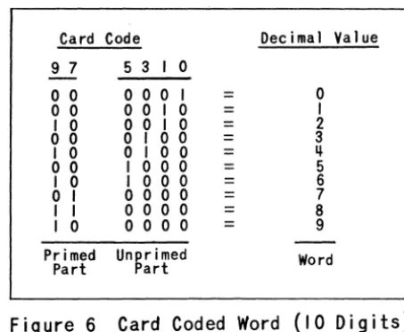
10-Card Code Decimal Value
9 7 5 3 I 0
o
0 000 I = 0o
0 001 0 = II 0 001 0 = 2
o
0o
I 0 0 = 3I 0
o
I 0 0 =II-o
0 100 0 = 5I 0 I 000 = 6
o
I 000 0 = 7I I 000 0 = 8
I 0
o
0 0 0 = 9Primed Un~r i med Word
Part art
Figure 6 Card Coded Word (10 Digits)
The primed word part, composed of the bits in card row positions 7 and 9, is stored in a second storage location. Two bits of the primed word part are un-used.
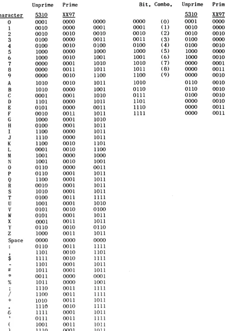
Figure 7 on page 9 is the complete 90-column card code and computer code table for all alphabetic, numeric, and special characters. Primed and unprimed parts of each character are noted and separated. The two XX's under the prime word column indicate the unused bit positions.
Card Word Identification
The 72 instruction causes an input card to be moved from the input magazine through both read stations, and the primed and unprimed word parts to be placed in buffer storage. The 96 instruction causes the card data to be moved from the buffer to main storage. To enable the programmer to identify each word part (primed and unprimed) and the main storage location it will occupy, the card words, illustrated in Figure 5, are given more definitive notations as shown in Figure 8.
:r :z:
..
0 12 3, 16WORD 0
J 10 J20
J
=
Unprimed portion of wordJ' = Primed portion of word
1st digit of subscript
=
Read station where data is sensed2nd digit of subscript
=
Word numberWORD 1 WORD 2 WORD'
J II J21 J I2 J 22 J I3 J 23
WORD • 0 '2
JIll- J 21p,
16
78
J' 10 J' 20 J'II J'21 J' 12 J'22 J'13 J' 23 J' J' III- 211-7 .
I , ,
.
. .
,.
.
10 It 12 11 14 IS 16 11 I I 19 10 21 » 2J N ~ H 21 H H ~ 31 U n ~ H H 37 • H • 41 .2 .3 . . asWORD 5 WORD 6 WORD 7 WORD 8 WORD 9
0 0
'2 J I5 J 25
J 16 J 26 J I7 J 27 JI8 J 28 J I9 J291~
3, J,
. 16 16
78
J'15 J' 25 J'16 J'26 J'17 J'27 J' 18 J' 28 J'19 J ~29 78
9 9
Card Code to Machine Code Machine Code to Card Code
£ar..d_CQ.d~ Maf.h.!.n~ £oQ.e_ Maf.h.!.n~ £oQ.e_ £ar..d_ £oQ.e_
Unprime Prime Bit. Combo. Unprime Prime
Character 5310 XX97 5310 XX97
0 0001 0000 0000 0000 (0) 0001 0000
1 0010 0000 0001 0001 (1) 0010 0000
2 0010 0010 0010 0010 ( 2") 0010 0010
3 0100 0000 0011 0011 (3) 0100 0000
4 0100 0010 0100 0100 (4) 0100 0010
5 1000 0000 1000 1000 (5) 1000 0000
6 1000 0010 1001 1001 (6) 1000 0010
7 0000 0001 1010 1010 (7) 0000 0001
8 0000 0011 1011 1011 ( 8) 0000 0011
9 0000 0010 1100 1100 (9) 0000 0010
A 1010 0010 1011 1010 0110 0010
B 1010 0000 1001 0110 0110 0010
C 0001 0001 1010 0111 0100 0010
D 1101 0000 1011 1101 0000 0010
E 0101 0000 0011 1110 0000 0011
F 0010 OOll 1011 1111 0000 0011
G 1000 0001 1010
H 0100 0001 1011
I 1100 0000 1011
J 1110 0000 1011
K 1100 0010 1101
L 0001 0010 1100
M 1001 0000 1000
N 1001 0010 1001
0 0110 0000 0011
P 0110 0001 1011
Q 1100 0001 1011
R 0010 0001 1011
S 1010 0001 1011
T 0100 0011 1111
U 1001 0001 1010
V 0101 0010 0100
W 0101 0001 1011
X 0001 0011 1011
y 0110 0010 0110
Z 1000 0011 1011
Space 0000 0000 0000
0110 0011 1111
• 1101 0010 1101
$ 1111 0010 1111
1101 0001 1011
# 1011 0001 1011
*
0011 0000 0001% 1011 0000 1001
; 1110 0011 1111
/ 1100 0011 1111
+ 1010 0011 1011
1110 0010 1111
& 1111 0001 1011
The meanings of these additional notations are as follows:
J = unprimed word part J' = primed word part
1st digit of subscript read station where card data was sensed 2nd digit of subscript = word number.
Data transferred from buffer to main storage is placed in specific main stor-age locations within a card input/output interlace. (Figure 12, pstor-age 18.) The word positions within main storage are not sequential, but are spread at inter-vals of 20 storage locations on the drum. This allows minimum latency access.
The fixed interlace pattern allows the programmer to identify the storage lo-cation of each word part within a particular storage band. In programming the buffer to main storage transfer, the programmer may specify only the storage band
into which the card data is to be, placed. However, a~ stated previously, the storage locations within the band are fixed. For example, Word 0 of an input card is always placed in a particular storage band in the following interlace pattern:
UnQrimed Word Primed Word Word 1t- 1st Read 2nd READ Band Storage
J 0 1 Var. 001 (JlO)
J 0 2 Var. Oll (J20)
J' 0 1 Var. 006 (J'lO)
J' 0 2 Var. 016 (J'20)
TIMING MECHANISM
Each time a row of a card is read at a read station, the roller underneath the card is pulsed during the time that the row of the card is being probed by the sensing brushes. When a row is not being probed by the brushes, or when there is no card in the read stations, the roller remains de-energized. The pulse placed on the roller when a row is read is called the Qrobe signal and is gen-erated by High-Speed Reader synchronizing circuits.
LATCH
FOLLO~ER
CAM
TIMING DISC FEED ARM 0
r - - - . TO CAPACITOR, ANO THEN TO BUFFER STORAGE EMPTY MAGAZINE
I
INFORMATION (BRUSHES)
TIMING DISC PHOTOCELL
PC 1 PC 1 TIMING DISC
INPUT EMPTY SWITCH SENSING STATIONS
REGISTRATION CHECK PHOTOCELLS JAM OETECTOR
0----CARD JAM
TRANSPORT ROLLERS
'-I---J---.~ SELECT STACKER NO.1
LJ--=---'I---c,----l~ SELECT ST ACKE R NO.1
I ' I '
r'
STACKER FULL SWITCHESL
_ _ --'. _ _ ---'-_ _ _ _+_. FULL STACKER OUTPUT STACKERS
PH~I~~~~LL LP::::RO~BE~ _ _ _ _ _ ~ _ _ --,
Figure 9 Electromechanical Schematic of Card Reader
The timing disc contains 12 slots located at intervals of 24 degrees around its circumference. A portion of the timing disc between the first and last slot (96 degrees) does not contain slots and is referred to as the ~.
While the High-Speed Reader is operating, the timing disc rotates and generates timing-disc photocell signals each time a slot passes between the photocell and its lamp. The timing disc rotates once for each card pass (card cycle) and generates 12 photocell signals per card, one for each row on the card. The photocell signals generate pulses which probe both read stations simultaneously and thus read the cards. If no card is in the read station, the photocell sig-nals do not generate any probe sigsig-nals.
Information from the read stations is assembled row-by-row in the card buf-fer band. It remains there until an instruction (96) transfers it to main storage. If no instruction is given, the next input instruction (72) will cause processing to stop. Both of these operations (data transfers from sta-tions to buffer and from buffer to main storage) are explained in detail in the following sections.
PROGRAMMING THE OPERATION CYCLE (See Figure lion page 17)
Next Card Cycle
The next 81 instruction must be given at least 3.5 milliseconds (assuming that the instruction is located in its minimum latency location which is 0198
+
201n) preceding the point at which the next punch set-up operation would start. This instruction should be given at least 264 milliseconds after the point at which the previous punch set-up started (giving a range of 132.5 milliseconds during which an 81 instruction may be given), if it is to be preceded by a test in-struction (22).Actually, a card cycle instruction (81) may be given 140 milliseconds
after the punch set-up operation is started (i.e. the point at which the punch set-up is completed), but there is no tes.t instruction by which the programmer can determine this point. Hence, the programmer must wait until 264 millisec-onds following the point at which the punch set-up started in order to use the test instruction. This insures that the card cycle instruction (81) can be given legitimately.
In unusual circumstances, it is possible that the programmer could time the 140 milliseconds by programmed operations and thus give the 81 instruction before the point at which the test instruction would pass. This however is not recommended. If the 81 instruction is not given early enough (at least 3.5 milliseconds before the proper point in the mechanical card cycle for the punch set-up to start) the time loss will be some function of how late the instruction is given, but not a linear function.
Stacker Selection
The stacker selection instruction (57) may be given during the 116 millisecond range starting 140 milliseconds after the start of the previous punch set-up operation. The 57 instruction must be given 20 milliseconds before the point at which the next punch set-up operation starts.
MODES OF OPERATION
The Read-Punch Unit has three basic modes of operation: 1) as a Read Unit only, 2) as a Punch Unit only, and 3) a combination of modes one and two.
Read Unit Only
In using the Read-Punch Unit as an input device only, every card cycle (81) in-struction will activate all portions of the unit for the following operations:
1) The sensing of information at Read Stations 1 and 2.
2) The transfer of information located in the to the punch positions of the card buffer. tions are specified by a given band in the struction.)
punch interlace positions (The punch interlace
in-Card Cycle
When the High-Speed Reader is energized, the electromechanical system that trans-ports the card through the card read cycle begins to function. A card is not sent through the Reader, however, until a 72 instruction (card cycle instruction) activates the picker knife which transports one card from the card feed magazine into the roller mechanism. Once the 72 instruction is given and the card enters the feed rollers, the programmer has no further control over the movement of the card until it reaches the selected output stacker. The programmer cannot control the data read from the card until it is completely accumulated in the buffer storage as a result of the 72 instruction.
The 96 instruction transfers both sets of input data from fixed locations on the buffer band to the interlace pattern in any desired band (specified in m in the instruction word) in the main drum storage.
Thus, input by the High-Speed Reader is accomplished by the use of the 72 (transfer from card to buffer) and 96 (transfer from buffer to main storage) program instructions.
Card-to-Buffer Transfer
The maximum feed rate in the High-Speed Reader is 450 cards per minute. The operations in the High-Speed Reader are overlapped so that the card in Read 1 and the card in Read 2 are both read simultaneously during each card cycle. These operations in the High-Speed Reader are all overlapped with computation, printing, and reading or punching by the Read-Punch Unit.
The mechanical card cycle operation (Figure 9) is initiated at specific intervals as determined by a continuously rotating cam (See Timing Mechanism section). Interlocks are provided for the card cycle (72 instruction) and the buffer-to-main storage transfer (96 instruction) to insure synchronization of the Central Processor with the High-Speed Reader. There are no stops in the High-Speed Reader card transport mechanism so that once the 72 instruction causes a card to be fed from the card feed magazine into the continuously
moving rollers, the card cannot be stopped until it reaches the selected output stacker.
Buffer-to-Main Storage Transfer
The buffer-to-main storage transfer instruction (96) is interlocked by another
flip-flop (buffer-loaded flip-flop) which indicates whether or not the buffer
is loaded. When a 96 instruction is given, the computer is interlocked if the
buffer is not loaded or if there is not a card under either set of read brushes.
A test instruction (42) is provided which samples the flip-flop to determine when the buffer loading is completed. Since cards are not stopped between the
two read stations, it is imperative that the programmer give the 96 instruction
in time for it to be completed before the point at which sensing of the next card begins.
To safeguard against the possibility of losing the card images, an "Alert 96"
button is provided on the operating panel of the Central Processor. When this button is depressed, the Central Processor will stop if the buffer was not
un-loaded at the proper time. If a 96 instruction is given with only one card
present in either read station, the buffer interlace locations of the station not occupied will read all binary one's.
Buffer Load Test
Figure 10 is a functional diagram of the operating cycle of the High-Speed Reader. "A" equals the range during which a 42 (buffer load test) instruction may be
passed. A 96 instruction may be given during the range except during the last
3.5 milliseconds of the range. The completion of a 96 instruction given during
the range resets the buffer loaded flip-flop which is otherwise reset by the
sensing of the next row 1. This would interlock another 96 instruction during
this range.
15 R ows
12 Rows
!
Range during which a 72 order ma¥ be Range during which a ~7 instruction
given without slowing up the maximum may be given
card speed
i
!
Preceding Card Cycle
Present Card Next Card
Cycle Cycle
A
---
---Row
9 Row I Row 9 Row 12
Buffer Loaded
Row
I
A = Range during which a ~2 instruction will pass
In Figure 10, the point at which the first row of the card is sensed is taken as the start of the card cycle and the reference point from which other points
in the card cycle are timed. Twelve rows from this reference point, the buffer
will be loaded with the sensed data of the card. Section A of the diagram in-dicates that a 42 instruction given anytime during the three row-times following the buffer being loaded will find the buffer loaded flip-flop set and will then transfer the contents of rC to rA and transfer control to the location specified by the m address part of the test instruction (42).
If, however, the test instruction is given during the last 3.5 milliseconds of the A range, the 96 instruction will bring in incorrect information.
Stacker Selection
The stacker selection instruction (47) for the card in Read 2 may be given after the buffer is loaded, but must be given before the start of sensing in row 12 of the following card in Read 2.
To maintain maximum card speed, the 72 instruction must be given during the range of 15 rows proceding the end of reading of row 9 of the present cards in the read stations. This includes 9 rows of the present card cycle and 6 rows of the previous card cycle. The actual operation of the picker knife, however, is not until row 3 of the next card cycle and the card does not
ar-rive at the first set of sensing brushes until 12 row-times later. (See
Fig-ure 11 for timing.)
INPUT CHECKING ROUTINE
Programmed input checks are incorporated into the High-Speed Reader routine. If the programmer elects to code his own routine, rather than utilize the existing routines supplied by Remington Rand, this operation can be designed as follows:
Compare (for equality) the first and second read interlace positions of the card. Read 1 data will be on the band chosen by the programmer on the buffer-to-main storage transfer for the first card; Read 2 data will be on an
alter-nate band. This comparison can be programmed in minimum latency, and will
allow time for stacker selection in case of a discrepancy between Read 1 and Read 2 of any card.
If the computer is to be stopped in the event of a comparison discrepancy, a "halt" routine, similar to that provided in the input routine, must be provided. This protects any information which may have accumulated for punching or
print-ing in the main program, or stored in back-up storages for output.
ERROR CONDITIONS
There are four basic error conditions which may occur during operation of the High-Speed Reader. They are:
2. Bad card registration at the read stations.
3. Full output stacker.
4. Card jam.
In each case, the succeeding 96 instruction after the condition has occurred will cause the computer to select the instruction word located at storage loca-tion c+l. The program should be designed to transfer a stop instrucloca-tion word to
rX. This instruction word identifies the error and supplies the address where
the next instruction will be located after the error has been corrected.
The program should then enter the stop subroutine of the High-Speed Reader routine which will permit saving of any data in the other input/output units. If the programmer wishes to ignore this condition, it is possible to do so by supplying a "skip" to the routine to be entered as the c+l address.
EFFICIENT UTILIZATION OF THE HIGH-SPEED READER
The High-Speed Reader can be programmed to operate at rates of up to 450 cards per minute. The Read-Punch Unit can be programmed to operate at rates of up to 150 cards per minute. Since the operation of both units can be overlapped, an operating ratio of three-to-one, or better, for these units can be achieved. Ther"efore, wherever possible, the programmer should keep the High-Speed Reader operating at full speed in order to obtain efficient equipment utilization. This,in turn,requires consideration in the areas of system design and machine programming.
System Design
During the initial design of a computer run, consideration should be given to which input units will receive the bulk of the input data. Wherever possible, the programmer should use the High-Spee.d Reader as the basic input device.
When the Read-Punch Unit is utilized as combined input/output, it is possible to limit the speed of the Reader and thus impair the overall efficiency of the computer operation. For example, where results are punched into every second card in the Read-Punch Unit, output efficiency will drop 50% even though the cards are transported through the unit at 150 per minute. Therefore, overall computer efficiency will be adversely affected unless there is an average of six cards per punched result being processed through the High-Speed Reader.
Programming Techniques
In all runs which use the High-Speed Reader, the programmer should consider methods of keeping the Reader operating at the maximum speed consistent with the processing and output. This can be accomplished through programming techniques
such as extending the buffer storage. In this case, reserve areas are allocated
in storage to store raw data until ready for processing. It is necessary to
TI'MING DISC REVOLUTIONS
1
2
3
4
5
PHOTOCELL SIGNALSROW COUNTER SIGNALS·* • • • • • • • • -J'L-J~-1'~/L-__ -1'~/L-J~-1'~/'-J~-1'~A-~-1'L-A--A. __ ~L-A-~~L-A-~~L-JL~~L-JL-l ____ JL~~~JL~~~JL-A~~JL~~~ __ -A~A-Jl~L-A-Jl~L-A-Jl-AL-A-Jl __ __
C~RD CYCLE COUNTER S I G N A L S . . . . ' A A " A
PICKERKNIFE FF SET • • * . * . . . , A
START CARD TRAVEL . . . * ... * . . . A
CAR 0 I N REA 0 S TAT ION 1 . . . u u A L-J CMI.O •
READ 8: TEMPORARILY STORE ROW 1. • A
TRANSFER ROW 1 TO BUFFER .. • • .. • • •
REA D 8: T E hi PO R A R I L Y S TOR E ROW 2. • ,'-_______________________________________________________________ _
TRANSFER ROW 2 TO BUFFER... • A
REAO 8: TEMPORARILY STORE ROW 12 • A.
T R • NSF ERR 0 W 1 2 TO B U F FER.. • • 4 A'-_______________________ _
BUFFER FULLY LOADED . . . • • • • • ~
CARD IN READ STATION 2... L..J -CI\u't.
"L-READ 8: TEMPORARILY STORE ROW 1. • A
TRANSFER ROW I TO BUFFER... A A
READ 8: TEMPORARI LY STORE ROW 2.. A
TRANSFER Row 2 TO BUFFER... • A
READ 8: TEMPORARILY STORE ROW 12 • A
TRANSFER ROW 12 TO BUFFER.... A A
BUFFER FULLY LOADED • • * * . . . • A
SELECT STACKER . . . * . . . A
Figure I I General Timing Diagram
STORAGE LOCATION STORAGE LOCATION
OOXX 01XX
00 50 00 50
01 JlO 51 J22 01 51
02 52 02 J15 52 J27
03 53 03 53
04 54 04 54
05 55 05 55
06 J'lO 56 J'22 06 56
07 57 07 J'15 57 J'27
08 58 08 58
09 59 09 59
10 60 10 60
11 J20 61 J13 11 61
12 62 12 J25 62 J18
13 63 13 63
14 64 14 64
15 65 15 65
16 J'20 66 J' 13 16 66
17 67 17 J'25 67 J' 18
18 68 18 68
19 69 19 69
20 70 20 70
21 J11 7li J23 21 71
22 72 22 J16 72 J28
23 73 23 73
24 74 24 74
25 75 25 75
26 J' 11 76 J'23 25 76
27 77 27 J'16 77 J'28
28 78 28 78
29 79 29 79
30 80 30 80
31 J21 81 J14 31 81
32 82 32 J26 82 J19
33 83 33 83
34 84 34 84
35 85 35 85
36 J'21 86 J'14 36 86
37 87 37 J'26 87 J' 19
38 88 38 88
39 89 39 89
40 90 40 90
41 J12 91 J24 41 91
42 92 42 J17 92 J29
43 93 43 93
44 94 44 94
45 95 45 95
46'J'12 96 J'24 46 96
47 97 47 J' 17 97 J'29
48 98 48 98
READ-PUNCH UNIT
GENERAL DESCRIPTION
The Read-Punch Unit of the UNIVAC Solid-State 90 is a dual purpose unit capable of both sensing and punching Remington Rand 90-column punched-cards. It is composed basically of a card input magazine, a first read station (Read 1), a punch station, a second read station (Read 2) and two output card stackers.
Under normal operating conditions, the Read-Punch Unit processes cards at a speed of 150 cards per minute. Prepunched or blank cards are first sensed at Read 1. The sensed information is placed in capacitor storage and then sent to a special area on the magnetic drum (Central Processor) called the card buffer storage. From the card buffer, the information is transferred to main storage where it is available for processing according to the program. The processed
information is then returned to the Read-Punch Unit and punched into cards at the punch station. The cards are then read at Read 2 to provide opportunity to check the identity and validity of both the Read 1 and card punch operations. Finally, the cards are sorted into the output stacker prescribed in the program. Figure 13 is a simple diagram of the input-output operation of the Read-Punch Unit.
II
InputMagazine
Magnetic Storage
Drum
Read Station
#1
Read-Punch Unit Buffer Areas
Punch
Station Station Read
#2
Figure 13 Functional Diagram Of The Read-Punch Unit
INPUT-OUTPUT LOGIC
Three program instructions control the operation cycle of the Read-Punch Unit. They are: 81, or card cycle instruction, (Read, Punch, and Move Cards); 46
(Transfer sensed information from the card buffer to main storage); 57 (Stacker selection). A fourth instruction (22) enables the programmer to test the buffer.
Instruction Codes
81 m c Transfer the output card images from the m band to the punch buffer. When the transfer is completed, the computer is free to operate on other instruc-tions. The Read-Punch Unit will then punch the data from the punch buffer area into the card in the punch station. It then reads the cards now in both read stations, storing their images in the Read-Punch input buffer. Finally all cards are advanced one card station to the right in the Read-Punch Unit. m must be a multiple of 200 (i.e. 0000, 0200, 0400, etc.) For minimum latency this instruction should be in
storage location 0198 + 201n.
46 m c Wait until the Read-Punch input buffer is loaded, then transfer the input card images to band m. (m must be a multiple of 200.) For minimum latency, this instruc-tion should be in storage locainstruc-tion 0198 + 201n.
22 m c This instruction permits the program to test the status of the Read-Punch input buffer. If the buffer is load-ed, (rC) is transferred to rA and the next instruction is found at m. If the buffer is not loaded the next instruction is found at c. rA is not altered in this case.
Word Time
203
203
3 i f c address
t~ken, other-wise 4
57 m c Select the output stacker designated by m. If m
=
0000 3 the uO stacker is selected, if m=
0100 the u1 stackeris selected. This instruction must be given wi~hin 116 ms after the Read-Punch input buffer is loaded if it is
to operate on the card at the second read station. Otherwise stacker UO is automatically selected.
Operation Cycle
Normally, the FEED ONE CARD button on the operating panel of the Read-Punch Unit
is depress~d three times to ready the unit for programmed operation. These fill
However, as shown in Figure 14 on page 22, the 81 instruction does not
coincide with the beginning of the mechanical card cycle. It indirectly starts
a card cycle, but, as shown in Figure 14, the instruction is given after ap-proximately three quarters of the card cycle that was initiated by the previous 81 instruction.
At the beginning of the card cycle, cards in the two read stations (Cards B and D in Figure 14) are sensed. At 334 degrees of the card cycle, the sensed information is placed in capacitor storage. Tha information is then read, 10 bits at a time, into buffer storage. When the sensed information is completely written onto the buffer band, a 46 instruction transfers the information from the buffer to main storage.
During the time the sensed cards are moving to the next stations, the pro-cessor carries out computations on the information read from the card moving into the punch station (Card B). The information to be punched in that card is then stored in main storage. Card C is punched, under control of the mechanical card cycle, with previously processed information while the data for Card B is being computed.
The next 81 instruction, containing the number of output word storage band in its m address, is staticized in the static register, and the output words are transferred to the card buffer band. When the output words are all in the buffers, synchronizing circuits store the indication that an 81 instruction has been given, and the instruction is then cleared from the Static Register.
Starting at 1340 of the mechanical card cycle caused by the previous 81
in-struction, the synchronizing circuits set up the punch actuators with the out-put words stored in the buffer. Ten bits at a time are transferred serially from the card buffer to the shift register. Next, the ten bits are transferred in parallel to the information distribution matrix, and then to the actuator matrix to set up the punches for the card (Card B) moving into the punch station. During punch set-up time, the other cards are also moving. The card that was punched (Card C) is moving into the second read station, and the card that was sensed (Card D) in the second read station is on its way to the output stackers. At this point in the program a 57 instruction must be given if the card is to
fall into stacker 1 instead of stacker O.
The first mechanical card cycle ends as the cards come to rest in their res-pective stations. The synchronizing circuits complete the setting up of the punches and generate a signal that starts the next mechanical card cycle. .A new card is fed, the cards in the read stations are sensed, and Card B in the punch station is punched.
1\.:1 1\.:1
2600
TIMING CAM
I
33~0
POSITION
I
'3qO
F"d Cud •
I
2600
I
Card A Moving
ation ,
Card B Mov i ng Card B At Rest
SenseCardB Punch Station
MECHANICAL CARD CYCLE OF
LAST 81 INSTRUCTION
Card 0 Moving [- Card 0 At Rest
Sense Card 0 Stacker
I
Punch Card Cl
C
~
Transfer~S Y N C H R O N I Z I N G C a r d Image
CIRCUiTS _ 0 Buffer_
C
. . . - = - \ Tran~sferi
~ From Buffer'
INSTRUCTION - - To Memor~
Output Words
PROCESSOR _ To Buffer _
PRESENT 81 I NSTRUCTI ON
C
r - - - I Tran-sfer IC
Calculate AndStore Output Words 'n Storage Band
[
Card C At Rest Read Stat ion 2SYNCHRON I ZI NG
C _
Set Up Pun~hes And StartCIRCUITS MechanIcal Cycle
~
_ _
--+ _ _ _ _ _ _ _
-t-_ _ _ _ _
~2600
Card Buffer Storage
The card buffer band on the magnetic storage drum is used to store information temporarily during input-output operations. As an intermediate storage between capacitory storage and main storage, the card buffer band is necessary because of the difference in speeds of operation of the relatively slow input-output units and the faster operating Central Processor.
The card buffer storage is used by both the High-Speed Reader and the Read-Punch Unit. Alth~ugh it is not a part of main storage, the buffer contains 200 word locations, the same as any of the 25 main storage bands. Locations 000-099
serve the High-Speed Reader; locations 100-199 serve the Read-Punch Unit.
During input-output operations, information read from cards or information transferred from main storage to be punched is stored temporarily in the card buffer (Figure 15). After it is recorded in the card buffer, the information can then be transferred to main storage or to the punch actuators in one drum revolution.
Input Bin
Ca.d P,th ::...;.~---..,;:..;.;..,..>
U
Read Stat i on -One
Figure 15 Read-Punch Unit
CARD WORDS
'-_ _ c_a_p_ac_i Storage t_o_r_-,L To Buffe r Sto rage
!
InputData
From Buffer ~Storage
Punch Actuators
Punch Station Read Station Two
Output Stackers
Information read from or punched into cards by the Read-Punch Unit is in the 6-bit Remington Rand punched-card code. Ten 10-digit computer words can be
punched into one 90-column card in card code, five words in the Upper Field and five in the Lower Field. Each card field contains four 10-digit words and one 5-digit word as shown in Figure 16. Although words 4 and 9 contain only
0 WORD 0 WORD 1 WORD 2 WORD 3 WORD' 0
IZ 12
3, l,
Ib Ib
78 78
, ,
.
.
,.
,.
.
,.
n" " ,. " " " II
..
20" " " " "
..
"..
"..
" ".. ..
HI I "
.. ..
..
" " I I.. ..
WORD 5 WORD
0 6 WORD 7 WORD 8 WORD 90
I~ IZ
J, 1,
I. S6
- '8 78
.
~ 9 9..
"....
..
" .,..
" " 50 " 50 51...
,..
.. .. ..
..
"..
I I 10 71 " n " ,. ,. " 71 . . •.,
I f I I..
..
I I 17...
Figure 16 Bas i c Format of Card Words
Primed and Unprimed Word Parts
To store a word recorded in card code in either buffer storage or main storage, (words are stored in 4-bit computer code), the card word (six bits per digit) is divided into two parts, a primed word part and an unprimed word part.
Figure 17 shows a 10-digit word composed entirely of numeric characters. The unprimed part of each digit in the word is composed of the four bits in card row positions 0, 1, 3, and 5 (lower-order bits). The unprimed word part can be stored in one computer storage location because it is exactly the size of a 10-digit, 4-bit computer word.
Card Code Decimal Value
9 7 5 3 I 0
o
0o
0 0 I=
0o
0o
0 I 0=
II 0 001 0
=
2o
0o
I 0 0=
3 I 0o
I 0 0=
~o
0 I 000=
5I 0 I 000
=
6o
Io
0 0 0=
7 I Io
0 0 0=
8 I 0o
0 0 0=
9Primed Unprimed Word
Part Part
Figure 7 on page 9 is the complete 90-column card code and computer code table for all alphabetic, numeric, and special characters. Primed and un-primed parts of each character are noted and separated. The two XX's under the prime word column indicate the unused bit positions.
Card Word Identification
To enable the programmer to identify each word part (primed and unprimed) and the main storage location it will occupy, the card words, illustrated in Fig-ure 16, are given more definitive notations. These notations, for input card words from Read 1 and Read 2 and for output card words, are shown in Figure 18 on page 26. The meanings of these additional notations are as follOWS:
I or 0 = Unprimed word part
I' or 0'
=
Primed word part1st digit of subscript
=
read station where card data was sensed2nd digit of subscript = card word number
Data transferred from buffer to main storage is placed in specific main storage locations within a card input/output interlace (Figure 20 page 32). Thus, by correlating the word notations in Figure 18 with the interlace storage
locations shown in Figure 20, the programmer may easily determine the main storage location of each card word part.
In programming the buffer-to-main storage transfer, the programmer may spec-ify only the storage band into which the card data is to be placed. This is
done by specifying the main storage band number in ~ of the 81 instruction.
However, as previously stated, the interlace pattern for input/output words re-mains the same for all bands of the main storage.
PROGRAMMING THE OPERATION CYCLE
Input from punched-cards and output to punched-cards in the Read-Punch Unit are accomplished by the use of the Card Cycle (81) and Read (46) instructions. The
81 instruction first transfers data from the output interlace of ~he ~ band of
main storage to the buffer band. When the main storage-to-buffer transfer is completed, the computer is free to operate on other instructions. The punch
actuators are set-up independently of the computer. When the set-up is completed, the card cycle automatically punches, reads, and moves cards in all stations. The absence of a card from the input magazine, Read l,or Read 2 causes an "empty station" indication which prevents the execution of the 81 instruction and
causes a transfer to c + 1. A button is provided on the control panel of the
Central Processor which allows the empty station signal to be ignored. If a
INPUT FROM
READ 1
OUTPUT FOR PUNCHING
INPUT FROM
READ 2
WORD 0 WORD 1 WORD 2
110 III 112
ItO
It
I 1'121 2 3 4 5 6 7 8 9 10 11121314151617181920 21 2223 24 25 26 27 28 2930
WORD 5 WORD 6 WORD 7
115 116 117
1'15 116 117
46 47 48 49 50 51 52 535455 5657 58 59 60 61 626364 65 66676869 70 71 72 73 74 75
WORD 0 WORD 1 WORD 2
010 0" °12
0'10 0'11 0'12
1 2 3 4 5 6 7 8 9 10 11121314151617181920 21222324252627282930
WORD 5 WORD 6 WORD 7
°15 °16 °17
0'15 0'16 0'17
46474849505152535455 5657585960 61 62636465 666768697071 72 737475
WORD 0 WORD 1 WORD 2
120 121 122
120 121 122
1 2 3 4 5 6 7 8 9 10 11121314151617181920 21 2223 24 25 26 27 28 29 30
WORD 5 WORD 6 WORD 7
125 126 127
1'25 1'26 127
4647484950 51 52535455 56575859606162636465 66676869 70 71 72 73 74 75
Frgure 18 Input and Output Card Words
WORD 3 WORD.
113 114
1'13 114
31 32 333435 36 37 38 39 40 4142434445
WORD 8 WORD 9
118 119
1,8 119
76 77 78 79 80 81 82 83 84 85 8687888990
WORD 3 WORD.
°13 °14
0'13 0'14
31 32 33 34 35 36 37 38 3940 41 42434445
WORD 8 WORD 9
°18 °19
0'18 0'19
76 77 78 7980 81 82 83 84 85 8687888990
WORD 3 WORD •
123 124
123 124
31 32 33 3435 36 37 38 3940 41 42434445
WORD 8 WORD 9
128 129
128 1'29
The 46 instruction transfers the input data (read from cards in both read stations) from fixed locations in the buffer band to fixed interlace loca-tions in any desired band in main storage. Before using the 46 instruction, it is necessary to determine, by means of a test instruction (22), whether the sensing of the cards has been completed.
The operations in the Read-Punch Unit are overlapped so that the following operations all occur once during each card cycle:
1) Reading the card at Read 1.
2) Punching the card in the Punch Station.
3) Reading the card at Read 2.
These operations in the Read-Punch Unit are all overlapped with computation, printing, and the operation of the High-Speed Reader as well.
Card Cycle
The card cycle instructioh (81) may be given at any time, but if an 81 in-struction is given in the 140 millisecond period during which the punch actu-ators are being set-up as a result of the previous 81 instruction, the machine will be interlocked until the punch set-up is completed. This situation should be avoided since it prevents exercising any control over the operation of the High-Speed Reader for a period of time that may be greater than one card cycle
in the High-Speed Reader. Actually, there is no advantage in giving an 81 in-struction that soon after the previous 81 inin-struction since a minimum time equal to the basic card cycle period must pass before the 81 instruction can be executed.
Punch Set-Up
When the card cycle instruction (81) is given, the computer immediately stores an indication of this in flip-flop and begins transferring the data from the output interlace in main storage to the punch buffer. The only exception to this occurs if the 81 instruction is given during the punch set-up time, in which case the machine is interlocked as described previously. This latency and transfer time (a minimum of 201 up to a maximum of 400 word times depend-ing upon the latency resultdepend-ing from the location of the 81 instruction) is the computer "execution time" required by the 81 instruction. When this buffer transfer is completed, the computer is free to proceed with the execution of other instructions in the mechanical card cycle. When the punch set-up has been completed, the card cycle flip-flop is reset.
Buffer-Loaded Test
for the buffer-loaded condition can be used to determine whether an 81 instruc-tion can be given as well as whether a buffer-to-main storage transfer (46) in-struction can be given. The use of the test inin-struction is the key to the pro-per timing and synchronization of the program and computer opro-peration with the Read-Punch Unit.
Figure 19 indicates the timing of the 81, 46, 57 and 22 instructions with relation to the Read-Punch operating cycle.
III !JOO ms II
•
396.5 msIII 386 ms II'
... 26!J ms II
1--- -- -- -
---I
I Range during
I I
217 ms which a 57
I
order ma~ be
I
I given I I ms
I I
~---r---Start of Punch Set-up 13ij.'O of mechanical card cycle
,
I
,
I
I 81 order may be Ranie during which
I
, given during this an I instruction
I range. But there may be given
pre-I
I is no way to test ceiled by a test (22)
I for range 126.5 ms Inst. 132.5 ms
I I I
~---Range during which a 22 Instruction will paSf pass and a !J6 order may be given 136 ms
Buffer Load i ng Comp I eted FA i p-Flop Set I!J of mechanical card cycle
Start of next punch Set-up
Figure 19 Diagram of Read-Punch Operating Cycle
In Figure 19, the point at which the punch set-up begins is taken as the start of the cycle and the reference point from which other points in the cycle are timed. This diagram shows that the buffer-loaded flip-flop will be set and the test instruction (22) will transfer (re) to rA and transfer control to the
location specified by the
m
address part of the test instruction~ This occursm represents a storage location or register
c represents the address of the next program instruction
(m) represents the contents of a storage location or register
rA represents Register A
rL represents Register L
rC represents Register C
rX represents Register X
Word Time
72 m c Pull a card into the continuously moving rollers of the feed. The card will be read at each station, in turn, and the data stored in the buffer band. The m address is ignored if executed. If a 72 order is given before the preceding 72 has begun to feed a card, the second 72 is not executed. Instead, (rC) go to rA and control goes to the m portion of the instruction in rC. The
computer is free to operate on other instructions dur-ing the movdur-ing and readdur-ing of the cards.
3 if c ad-dress taken, otherwise 4
96 m c Wait until the High-Speed Reader buffer is loaded, then transfer this data from the buffer to the memory band m
(m must be a multiple of 200).
For minimum latency this instruction should be placed in cell 0198 + 201n.
Word Time
203
42 m c This instruction permits the programmer to test the status of the High-Speed Reader buffer. If the buffer is loaded (rC) is transferred to rA and the next instruction is
3 i f c ad-dress taken, othersise 4 found at m. If the buffer is not loaded, the next
instruc-tion is found at c. rA is not altered in this case.
47 m c Select output stacker designated by m. If m = 0000 the UO stacker is selected, if m = 0100 the ul stacker ts selected and if m
=
0200 the u2 stacker is selected. To operate on the card at the second read station, this instruction must be given within 120.8 ms after the image is available in the buffer. If not, the card will enter the previouslyse-lected stacker.
3
Note: If a 96 instruction is given with only one card present in either read station, the buffer interlace locations of the station not occupied will read all binary l's.
3) The punching of this information into the card at the punch station.
Therefore the machine zeros must be transferred to the punch interlace posi-tions as an initializing step in the program. The interlace posiposi-tions can not be used as storages during the program. As an alternative, when the programmer does not wish to punch data into a card, the necessary coding may be provided to transfer machine zeros to the interlace positions whenever a punch cycle is to be initiated. The programmer should also keep in mind that he is processing unchecked data when using the Read-Punch Unit as an input device since the data cannot be checked until it has been read at Read 2.
Punch Unit Only
In using the Read-Punch Unit as an output device only, the programmer needs only to ignore the Read 1 positions in the interlace, and check the Read 2
posi-tions against the data supplied for punching. If there is information
pre-punched into the card, this should be considered when checking in order to have a valid second read. For further information on this subject, refer to the Back-up Punching Routine.
Combination Read~Punch
When using the Unit as both an input/output devi~, all of the considerations
described primarily must be kept in mind by the programmer. For purposes of checking, he must save the information from Read 1 and from the punch station, and if necessary, compare certain portions of itro obtain equality between card words in the Read 2 check.
PROGRAM CHECKING
All checking of the Read-Punch Unit is accomplished by comparing for equality the contents of the second read interlace positions with the contents of the combined card words from the punch interlace positions and the first read inter-lace words. Sufficient time is provided to perform a stacker selection order after making these comparisons if an error is detected. If the error is con-sidered by the programmer to be one which should stop further operations, the programmer should supply a stop order to rX containing information in the m
portion of the word identifying the type of error. The program should the~en
ter the Stop subroutine of the High-Speed Reader routine in order to protect
other input/output information. (Note: Input data is not checked until this
ERROR CONDITIONS
There are four basic error conditions which may occur during operation of the Read-Punch Unit. They are:
1. Full output stacker.
2. Empty Read or Punch stations.
3. Empty input magazine
4. Card jam.
In each case, the succeeding 81 instruction after the condition has occurred will cause the computer to select the instruction word located at storage
loca-tion c+l. If operations are to be stopped as a result of either of these error
conditions, the program should be designed to transfer a "stop" instruction word
to rX containing information in the ~ portion of the word identifying the type
of error. The program should then enter the Stop subroutine of the High-Speed routine in order to protect other input/output information.
STORAGE LOCATION STORAGE LOCATION
OOXX 01XX
00 50 00 50
01 51 01 110 51 122
02 115 52 127 02 52
03 53 03 0' 19 53 0' 12
04 54 04 54
05 55 05 55
06 56 06 I' 10 56 1'22
07 1'15 57 1'27 07 57
08 58 08 010 58 017
09 59 09 59
10 60 10 60
11 61 11 120 61 113
12 125 62 118 12 62
13 63 13 0'10 63 0' 17
14 64 14 64
15 65 15 65
16 66 16 1'20 66 1'13
17 1'25 67 1'18 17 67
18 68 18 015 68 013
19 69 19 69
20 70 20 70
21 71 21 III 71 123
22 116 72 128 22 72
23 73 23 0' 15 73 0 '13
24 74 24 74
25 75 25 75
26 76 26 I'll 76 1'23
27 1'16 77 1'28 27 77
28 78 28 011 78 018
29 79 29 79
30 80 30 80
31 81 31 121 81 114
32 126 82 119 32 82
33 83 33 0 '11 83 0' 18
34 84 34 84
35 85 35 85
36 86 36 1'21 86 1'14
37 1'26 87 1'19 37 87
38 88 38 016 88 014
39 89 39 89
40 90 40 90
41 91 41 112 91 124
42 117 92 129 42 92
43 93 43 0' 16 93 0' 14
44 94 44 94
45 95 45 95
46 96 46 1'12 96 1'24
47 1'17 97 1'29 47 97
48 98 48 012 98 019
HIGH-SPEED PRINTER
GENERAL DESCRIPTION
The High-Speed Printer prints in a variety of formats, controlled by the program,
at a speed
of
up to 600 lines per minute. Fifty-one print characters areavail-able including 26 alphabetics, 10 numerics, and 15 symbols and punctuation marks.
The High-Speed Printer produces printed lines of computed or tabulated results 130 characters wide, spaced six lines per inch vertically, and containing 10 char-acters per inch horizontally. Any sprocket-fed paper up to and including card stock, either blank or preprinted, can be printed by the High-Speed Printer. At least five carbon copies and one original copy can be produced by using paper
between 11 and 13.5 pounds in weight. Impression control permits variation in
the strength of the printing hammer stroke.
OUTPUT LOGIC
Under control of program instructions, information to be printed is first
trans-ferred from main storage to the print buffer on the magnetic storage drum. From
the buffer the information is transferred to the print mechanism of the High-Speed Printer.
The printing cycle is controlled by two instructions, 11 and 16. The 11
in-struction accomplishes the main storage-to-buffer data transfer, a paper advance, and the printing by the High-Speed Printer. The 16 instructions accomplishes paper advances (up to 79 lines) by the High-Speed Printer.
These instructions, and others which are related to the printing operation, are discussed in detail later in this manual.
Print Words
The 130 characters that can be printed one one line are divided into 13 10-digit
print words. These words, and their corresponding print positions, are shown
in Figure 21. Before a print instruction is executed, the 13 print words are accumulated by program instructions on a specific main storage band in fixed word locations of the print interlace pattern.
Pr i n t Wo rd """,TmTTT'l""":'irmrTT'T"nTTmTTT"T"TTm'T1TlTrii'TTnrrrrrTrrTTTTTTTi'i-mTTTTTTnT111'TTT1rTrrrrTT'T'1"1'TTTTTTTTTTTTT'T1TITTT'iTmI'Tm"';"m Print Line
Position
Print Interlace
Information stored in the print interlace is in 6-bit Remington Rand punched-card code, and thus requires two storage locations (words are stored in 4-bit computer code). Therefore, each print word is divided into two parts, a primed word part and an unprimed word part.
The primed word part is composed of the four lower-order bits of each character