R E S E A R C H
Open Access
Data-precoded algorithm for
multiple-relay-assisted systems
Sara Teodoro
*, Adão Silva, João M Gil and Atílio Gameiro
Abstract
A data-precoded relay-assisted (RA) scheme is proposed for a system cooperating with multiple relay nodes (RNs), each equipped with either a single-antenna or a two-antenna array. The classical RA systems using distributed space-time/frequency coding algorithms, because of the half-duplex constraint at the relays, require the use of a higher order constellation than in the case of a continuous link transmission from the base station to the user terminal. This implies a penalty in the power efficiency. The proposed precoding algorithm exploits the relation between QPSK and 4L-QAM, by alternately transmitting throughLrelays, achieving full diversity, while significantly reducing power penalty. This algorithm explores the situations where a direct path (DP) is not available or has poor quality, and it is a promising solution to extend coverage or increase system capacity. We present the analytical derivation of the gain obtained with the data-precoded algorithm in comparison with distributed space-frequency block code (SFBC) ones. Furthermore, analysis of the pairwise error probability of the proposed
algorithm is derived and confirmed with numerical results. We evaluate the performance of the proposed scheme and compare it relatively to the equivalent distributed SFBC scheme employing 16-QAM and non-cooperative schemes, for several link quality scenarios and scheme configurations, highlighting the advantages of the proposed scheme.
1. Introduction
The use of relays is considered an important technology for future wireless systems, because of its potential to increase capacity, extend coverage, and improve access fairness, as well as to provide additional flexibility in the upgrading of the networks [1]. It can be achieved through cooperation of terminals, either dedicated or user terminals acting as relays, which share their anten-nas and thereby create a virtual input multiple-output (MIMO) system [2]. These allow single-antenna devices to benefit from spatial diversity without the need for co-located additional physical antenna arrays.
Several cooperative diversity protocols have been pro-posed and analyzed to demonstrate the potential bene-fits of cooperation [3-5]. Some authors research the theoretical diversity-multiplexing trade-off of coopera-tive systems, such as in [6]. Furthermore, in [7] the Ray-leigh performance of a single-relay cooperative scenario with multiple-antenna nodes is investigated, deriving pairwise error probability (PEP) expressions. Research
has advanced beyond Rayleigh channels, considering more complex channel models for the cooperative chan-nel links, modeled, for example, by Rician or Nagakami-mmodels, such as in [8,9].
Other works resulted from the association of two high-performance techniques: the use of relaying chan-nels and multiple antennas at the transmitting and receiving sides. Furthermore, most of the extensive lit-erature on cooperative relaying diversity considers that RNs are equipped with a single-antenna, although some works have explored the benefits of multiple antennas in the cooperating nodes. It is fairly easy to deploy mul-tiple antennas arrays in infrastructure-based fixed relay networks, which increases the interest in MIMO relay-ing [10].
Despite the advantages mentioned in using the RA schemes, they require the use of constellations with higher cardinality in comparison with the continuous link transmission from the base station(BS) to the user terminal(UT), when this is available. This is due to the half-duplex constraint in RNs [3]. Despite achieving full diversity, these schemes cannot achieve full spectral effi-ciency, since they use two phases for transmission, thus * Correspondence: [email protected]
DETI, Instituto de Telecomunicações, University of Aveiro, Aveiro, Portugal
achieving half of the bandwidth efficiency of the equiva-lent non-cooperative systems. Consequently, the use of constellations with more symbols is considered in these cases as a means to achieve the same transmission rates of the non-cooperative ones, but it leads to a power effi-ciency penalty. Some examples of these RA schemes use distributed orthogonal algorithms, such as the ones in [11-15]. Capacity for a RA system with one and two RNs with single-antenna terminals was studied in [16]. In such study, it was found that the use of relays to assist a communication with the objective of increasing its capacity is only effective in high path-loss scenarios, because of the half-duplex constraint of RA schemes. It was also concluded that RA schemes that do not have transmission through the DP have lower performances than similar ones having such contribution, when the DP has a good transmission quality. For example, non-orthogonal protocols for cooperative systems with two or more relays were developed with the objective of increasing capacity or diversity order of cooperative sys-tems, such as in [17,18]. These proposals require the existence of the DP; therefore, in situations with poor direct link conditions, their performances are signifi-cantly degraded and, in case of outage of one relay, some information can be lost. Motivated by the fact that it is common to have large objects or other hindrances affecting the DP, the authors of [19] proposed a new algorithm for these situations, while bringing RA perfor-mances close to the continuous link transmission. This algorithm was derived for a two-relay-assisted scheme, exploiting the relation between QPSK and 16-QAM, by alternately transmitting through the two relays, to achieve full diversity and significantly reduce power pen-alty. Further along the development of cooperative sys-tems, some relay precoder designs were also proposed, however with different goals, such as providing robust-ness through the use of relays considering imperfect channel state information (CSI) [20,21].
Concerning the system-oriented application of RA schemes, these have been studied for different cases. For cellular systems, RA techniques have been also applied to multicarrier communications, such as in orthogonal frequency-division multiplexing (OFDM) systems. These are widely used for high-speed data transmission in wireless standard technologies, such as Wimax and LTE, because of the advantages mentioned above, and its abil-ity to eliminate ISI. An OFDM-oriented approach is used in this work, since relay networks combined with OFDM technology can make a strong platform for future wireless communications [11,22].
In this article, we extend the work of [19] on data pre-coded for two-relay-assisted scheme, to data prepre-coded
for a generic multiple L-relay case, where each RN is
equipped with either one or two antennas. In this
algorithm there is no need to transmit through the direct link, in alternative to the non-orthogonal algo-rithms proposed previously. This is beneficial for most scenarios, since the direct link is usually strongly affected by path loss or shadowing. A data-precoding of the data symbols prior to transmission is performed, fol-lowed by decoding at the UT by using the Viterbi algo-rithm [23]. The theoretical analysis of the PEP of the proposed algorithm is derived and confirmed with numerical results. Moreover, we show the analytical derivation of the gain obtained with the data-precoded algorithm, in comparison with distributed ones. The performance of the proposed scheme is evaluated and compared relatively to distributed space-frequency block code (SFBC) and non-cooperative schemes, for several channel quality scenarios and scheme configurations.
The remainder of the article is organized as follows: in Section 2, a general description of the system model considered is presented. We then describe the proposed algorithm and derive the main link equations in Section 3. Section 4 follows with the derivation of the theoreti-cal gain obtained with the proposed algorithm against the distributed SFBC algorithms, for a generic system configuration. PEP derivation and diversity analysis are shown for the proposed algorithm in Section 5, includ-ing the comparison between theoretical and simulation results. Then, in Section 6, the performance of the data precoded algorithm is assessed and compared with the reference cooperative and non-cooperative systems. Finally, we point out the main conclusions in Section 7.
2. System model
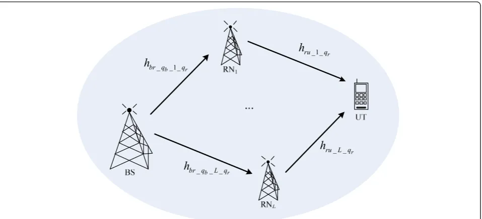
Let us consider a general 4G cooperative communica-tion system, in the downlink transmission. The rates required for downlink transmissions are generally higher than for the uplink, and therefore cooperation will be more beneficial when applied to the downlink, reason why we focus on this case. This RA system includes dif-ferent configurations with difdif-ferent numbers of nodes
and antennas. We further consider that there areLRNs
cooperating with a BS and a UT, as shown in Figure 1.
When L is zero, the system is considered to be
non-cooperative. When at least one RN is cooperating with the point-to-point communication, the system can be referred to as RA system.
We assume that the BS and UT are equipped with NB
and NUantennas, respectively. RNs are considered to be
dedicated and fixed nodes, equipped with NRantennas.
In addition, relays are considered to be half-duplex. Since different cooperative schemes can be considered by changing the number of antennas in each terminal,
their designation can be simplified to the form RA L
RN-NB×NR×NU. Similarly, the non-cooperative systems
andNUantennas at the BS and UT, respectively, which
can be generically referred to as NRANB×NU.
In practical systems, the BS is usually equipped with multiple antennas, since the size, cost, and other physi-cal problems are much less stringent than in the UTs. This generally leads to lower bit error rates (BERs) for the links between the BS and the RNs. We consider that the relays are strategically located so that they have a good quality link between the BS and themselves. Furthermore, we can assume to have a selective decode-and-forward relay protocol by considering that each is capable of deciding whether or not it has decoded cor-rectly. If an RN decodes correctly, it will forward the BS data in the second phase, otherwise it remains idle. This can be achieved through the use of cyclic redundancy check codes. This decision can also be approximated by setting a signal-to-noise ratio (SNR) threshold at all the RNs; the RN will only forward the BS data if the received SNR is larger than that threshold [12,24]. Furthermore, we focus our efforts on the special case where the direct link transmission is strongly affected by large-scale losses, such as due to shadowing, and thus no DP is considered for communication.
The expressions modeling the received signals at RNs depend on the space-time-frequency processing at the BS. To simplify, and to allow us to derive theoretical formulas, we assume error-free links between the BS and the RNs, and thus the symbols retransmitted by the RNs are the same as the ones transmitted by the BS.
Most of the scenarios consider the BS® RN channels
as error-free, but we also obtain numerical results assuming non error-free links between those terminals.
In this case we assume 2 × 1 space-frequency block cod-ing scheme from BS to each RN. The received signal expressions at the relays were derived in [25].
Since the systems haveLNR independent paths from
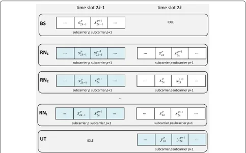
the relays to the destination, diversity can be achieved. Assuming the half-duplex nature of relays, we consider two algorithms for a RA scheme communication In the first one, distributed SFBC algorithm, we have two phases: in a first phase the BS broadcasts the informa-tion to the relays and in the second phase the relays retransmit the received information to the UT, emulat-ing a SFBC in a distributed manner. The flow of signals is described in Figure 2, for the case of single-antenna RNs and an OFDM-based system. The received symbols are represented in blue, while the transmitted ones are in white. The first (second) phase of transmission corre-sponds to the odd (even) time slots. Concerning the notation used, spk refers to symbols transmitted by the
BS at time slot kand subcarrier position p; zRi,p
k refers
to symbols transmitted by the ith RN at time slotkand
subcarrier positionp; and, ykp to the symbols received in the UT. In this approach, spatial diversity can be achieved, but because of the half-duplex constraints of relays, the information has to be transmitted during half of the time that would be needed in the case of a con-tinuous link available from the source to the destination. This means that, assuming that a modulation scheme
carrying mbits per symbol could be used in the case
when the continuous direct link is available, one would
need to switch toward a modulation carrying 2m bits
per symbol (if the symbol duration was kept identical). B EBB U
EU T T
K
B EB B U
EU T / T
K
BB U
UX T
K
B B U UX / T
K
As a major consequence, the increasing of the modula-tion order leads to a decrease of power efficiency.
The second algorithm presented, data precoded RA (PRA), aims to solve this spectral efficiency problem. In this proposed algorithm, the relays receive and transmit alternately, while the source is transmitting continu-ously, maintaining the same spectral efficiency as com-pared to the non-cooperative scheme. In order to get full diversity the data symbols are precoded at the BS. The flow of data information for this algorithm is shown in Figure 3, considering single-antenna RNs shown. Signal expressions of this scheme are presented in detail in Section 3. The rate of the proposed scheme isNl/(Nl+1), whereNl is the number of OFDM frames
transmitted, which is close to 1 for large values ofNl.
3. Data PRA algorithm
We consider that the number of antennas at the relays can be one or two. Note that a distributed space-fre-quency code should be implemented in the relays with more than one antenna and that there exist only fully orthogonal codes with unitary rate for a maximum of two antennas [26]. The relays receive and transmit alter-nately and the source is transmitting continuously, first
sending information to RN1 and then repeating it to
RN2, and then successively until RNL. Diversity is
achieved by using a data-precoding at the BS. There is no need for any extra processing at the relays. At the UT a soft decoding is obtained using MRC, followed by a final decoding based on Viterbi algorithm. This decod-ing method increases the complexity of the proposed scheme compared to distributed SFBC one, but on the other hand it improves the scheme performance. The complexity of this algorithm requires O(4Ns)
arithmeti-cal operations, where 4 comes from the number of
QPSK symbols and Ns is the number of states of trellis
diagram given by Ns= 4L-1. The nodes that are
trans-mitting and receiving in each instant are exemplified in
Table 1 where A® B represents the transmission from
node A to node B. Preliminary derivations and results for two relays, each equipped with one or two antennas, were presented in [19]. In this article, we extend the proposed data-precoded-based algorithm for a generic number of relays. The source produces a sequence of symbols {xk}, each one carryingminformation bits. The
BS transmitter precodes successive groups of symbols {xk,xk-1,...,xk-L }, using a bijective function F(xk,xk-1,...,x k-L). The precoded symbols,sk, are alternately transmitted
to the relays, allowing each symbol, when all paths are
available, to reach the UT through L-independent links.
time slot 2k-1
… …
subcarrier p subcarrier p+1 2 1
p k
s 1
2 1 p
k
s
BS
time slot 2k
… …
subcarrier p subcarrier p+1 2 1
p k
s 2 11 p
k
s
RN
1subcarrier p subcarrier p+1 2
p k
s 1
2 p k
s
… …
… …
subcarrier p subcarrier p+1
2,
2 1 R p k
z 2 1 p
k
s
RN
2subcarrier p subcarrier p+1
UT
subcarrier p subcarrier p+1 2
p k
y 1
2 p k
y
… … IDLE
IDLE
… …
subcarrier p subcarrier p+1 2 1
p k
s 1
2 p k
s
RN
Lsubcarrier p subcarrier p+1 2
p k
s 1
2 p k
s
… …
…
2 1 p
k
s 2
p k
s 1
2 p k
s
… …
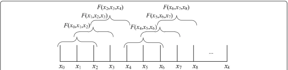
When one of the links fails, the bijectivity allows for the recovery of the original symbols QPSK. The groups of original symbols that are joined in a single precoded symbol are shown in Figure 4, when considering the particular case of having three RNs.
In the case where original symbols are QPSK, we pro-pose to use a simple precoding operation that relates
QPSK andM-QAM. It is easy to verify that a symbols
belonging to a regular 4L-QAM can be expressed as the
superposition of L QPSK symbols, s=L−1
n=02 −nxn,
which is easily derived by the definition of M-QAM
modulated signals presented in [27]. The precoded sym-bols, which are transmitted by the BS, are then given by
sk=μ
L−1
i=0
2−ixk+i, (1)
where xk is the kth QPSK symbol of the original
sequence information, with unitary power; μis the
uni-tary normalization factor for a generic number of relays, which is independent of the number of antennas in each relay, and was derived by us, according to the presented algorithm:
μ=
4L−1
L−1
i=0
4i
.
(2)
From Equation (1), we easily recognize each symbol sk
as aM-QAM symbol, with M = 4L. However, the
recei-ver will interpret it as a sum of LQPSK symbols, thus
bringing the performance close to the one that would be achieved if the QPSK symbols were transmitted con-tinuously, because of the fact that each QPSK symbol is received throughL paths. WhenLf(Lf<L) of the links
fails, it is possible to recover the original symbols QPSK from the L-Lfavailable links, although the diversity is
reduced toL-Lf.
In this algorithm, while BS continuously transmits data to the RNs, relays transmit and receive alternately, as shown in Table 1. Thus, the received signal at UT, in
time slot 2k-1
… …
subcarrier p subcarrier p+1
2 1
p k
s 1
2 1
p k
s
BS
time slot 2k
… …
subcarrier p subcarrier p+1
2 1
p k
s 2 11
p k
s
RN
1subcarrier p subcarrier p+1
2 1
p k
s 2 11
p k
s
… …
RN
2subcarrier p subcarrier p+1
2
p k
s 1
2
p k
s
… …
UT
subcarrier p subcarrier p+1
2
p k
y 1
2
p k
y
… …
… …
subcarrier p subcarrier p+1
2
p k
s 1
2
p k
s
2 1
p k
y 1
2 1
p k
y
… …
subcarrier p subcarrier p+1
RN
L…
IDLEIDLE IDLE
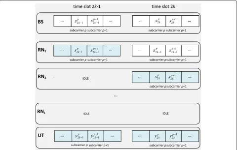
Figure 3Transmitted (white slots) and received (blue slots) signals for each node for data PRA algorithm.
Table 1 Active links in each time slot for the data-PRA scheme
Ts L-1 L L+1 L+2
Active links BS®RNL BS®RNL+1 BS®RNL+2 BS®RNL+3
time slotsLk+l, withl= 1,..,Land kÎN, for the case thatNRis equal to one and two, is given by
yLk+l=
⎧ ⎪ ⎪ ⎨ ⎪ ⎪ ⎩
μ2h
ru l1,Lk+l L−1
i=0 2−ix
Lk+l−1+i+nLk+l ,NR= 1
μ2
2
h
ru l1,k,p
2
+hru l2,k,p
2L−1
i=0 2−ix
Lk+l−1+i+nLk+l,NR= 2
(3)
where hru l qr,k=
βlhRru l qr,k represents the
coopera-tive channel for the link between the qthr antenna of
RNland the UT; hRru l qr,k is the complex flat fading
Ray-leigh channel realization for time slotk, with unit
aver-age power; and, bl represents the long-term channel
power.
4. Asymptotic gain of the proposed algorithm over distributed SFBC
The proposed algorithm has a trellis structure for the transmission of the QPSK symbols with four states. The minimum distance of the proposed scheme is obtained assuming a specific symbol is transmitted and calculat-ing the Euclidean distance between the correct decodcalculat-ing path and the minimum erroneous path. For the case of
L = 2 and assuming that symbol u(1) is transmitted
(note that the code is linear), this measurement is obtained through the paths of trellis structure repre-sented in Figure 5, corresponding to the paths that cor-rectly recovers u(1) and that erroneously recover u(i)
instead of u(1). Each path in the figure has the corre-sponding cost-function value. For the general case of
havingL relays we get similarly the squared minimum
distance of the proposed algorithm for single-antenna relays given by
d2minPRA=μ2d2minQPSKmin
j∈J
L−1
i=0
4−ihru i+L1,k2
, (4)
with J Î {1, 2, ..., L} and assuming that
hru l qr,k=hru l+L qr,k.
Let us definermias the channel power gains of each
link comparatively to the maximum channel power gain. Assuming, without loss of generality, that |hru_1_1,k|2 ≥|
hru_2_1,k|2 ≥ ... ≥ |hru_L_1,k|2, we obtain the channel
power gain for each link for relays with one antenna and fori= 1,...,L-1:
ρmi=
hru i+1 1,k2
hru1 1,k
2 . (5)
Thus, using the variables of channel power gains, Equation (4) can be simplified to
d2minRA−prec=μ2d2minQPSK
L−1
i=1
4iρmi+ 1
hru i1,k2. (6) Figure 4Groups of symbols alternately transmitted to each relay, according to a bijective functionF(xk,xk+1,xk+2) for the case ofL= 3.
N
X
X
NX
NB B
L
UX O N
K
X
X
P
§
¨
·
¸
©
¹
B B
UX O N
K
X
X
P
§
¨
·
¸
©
¹
B B
L UX O N
K
X
X
P
§
¨
·
¸
©
¹
B B
UX O N
K
X
X
P
§
¨
·
¸
©
¹
X
LX
Figure 5Trellis code for the RA precoded algorithm between symbolsu(1)and u(i), for
Similarly, for the case of relays equipped with two antennas, we can assume that |hru_1_1,k|2+ |hru_1_2,k|2 ≥
|hru_2_1,k|2 + |hru_2_2,k|2 ≥... ≥|hru_L_1,k|2 + |hru_L_2,k|2,
and thus obtain the corresponding channel power gains fori= 1,...,L-1 in
ρmi=
hru i+1 1,k2+hru i+1 2,k2
hru1 1,k
2
+hru1 2,k
2 , (7)
and the squared minimum distance in
d2 minRA - Prec=
μ2 2d 2 minQPSK L−1 i=1 4iρ
mi+ 1 hru l1,k
2 +hru l2,k
2
(8)
where the factor 1/2 comes from the normalization of the transmitted power, since in this case we have two antennas in each relay, and thus each antenna transmits one half of the total power.
It is important to evaluate the performance achieved with the precoded algorithm comparatively to the one we get using conventional cooperative algorithms. First we compare the precoded algorithm with one using dis-tributed SFBCs, with unitary multiplexing rate. For the cases of having more than two transmitting antennas, the SFBCs are not fully orthogonal, thus resulting in lower performances. Derivation of the gain and the minimum distance expressions, for the distributed algo-rithm, is detailed in Appendix 1. We present the theore-tical gain obtained with the PRA algorithm considered relatively to the distributed SFBC, forLÎN\{1} andNR Î{1, 2}, obtained from Equation (A.5), given by
GL≈10 log
⎛ ⎜ ⎜ ⎜ ⎝ 15L
L−1
i=1
4iρ mi+ 1
24L−1 L−1 i=1
ρmi+ 1
⎞ ⎟ ⎟ ⎟
⎠, (9)
where the channel gainsrmiare defined in Equation
(5) for the case of a single-antenna relays and in Equa-tion (7) for the two-antenna case. This obtained gain can also be seen as a lower-bound forNR> 2, because
of the non-achievement of full orthogonality in those cases. In the asymptotic case of high SNR values and when channels have equal power gains, the gain tends
to a constant irrespective of the number of relays, L,
given by
lim
SNR→∞GL= 10 log
5 2
. (10)
An alternative scheme for comparison with the pro-posed one is an equivalent cooperative scheme, also with a unitary rate, though fully orthogonal. This coop-erative scheme can use the Alamouti code multiple times according to the number of elements and is
referred to as distributed-compound-Alamouti (DCA) algorithm. This algorithm requires more time for trans-mission, which depends on the number of relays. Thus, for the case of single-antenna relays, it takes twice the time to transmit as compared to the time that the con-tinuous link would take if available for the two-relay case, and thrice the time for three- and four-relay cases and so forth.
The derivation of the gain obtained with the precoded algorithm with the DCA one is also derived in Appendix 1. In the case of high SNR regime and when channels have equal power gain, this asymptotic gain for a
gen-eric system with L relays, obtained through Equation
(A.8), is given by
lim SNR→∞GL=
⎧ ⎪ ⎪ ⎪ ⎪ ⎪ ⎪ ⎪ ⎪ ⎪ ⎪ ⎪ ⎪ ⎪ ⎪ ⎪ ⎪ ⎪ ⎪ ⎪ ⎪ ⎪ ⎪ ⎪ ⎪ ⎪ ⎪ ⎨ ⎪ ⎪ ⎪ ⎪ ⎪ ⎪ ⎪ ⎪ ⎪ ⎪ ⎪ ⎪ ⎪ ⎪ ⎪ ⎪ ⎪ ⎪ ⎪ ⎪ ⎪ ⎪ ⎪ ⎪ ⎪ ⎪ ⎩ 10 log ⎛ ⎜ ⎜ ⎜ ⎜ ⎜ ⎜ ⎜ ⎝ 4 ⎛ ⎝4 L
2+1−1
⎞ ⎠
3L(L+ 2)
⎞ ⎟ ⎟ ⎟ ⎟ ⎟ ⎟ ⎟ ⎠
,Lis even∧NR= 1
10 log ⎛ ⎜ ⎜ ⎜ ⎜ ⎜ ⎜ ⎜ ⎝ 4 ⎛ ⎝4
L+ 3
2 −1
⎞ ⎠
3L(L+ 3)
⎞ ⎟ ⎟ ⎟ ⎟ ⎟ ⎟ ⎟ ⎠
,Lis odd∧NR= 1
10 log
24L−1
L2
,NR= 2
. (11)
Thus, the asymptotic gain that the precoded algorithm achieves relatively to the DCA one, when the channels have equal power gains, depends on the number of RNs and the number of antennas in each one. This gain in dBs in function of the number of RNs is shown in Fig-ure 6. When the number of antennas in each relay is two, the gain increases with the number of relays, since Alamouti code is implemented in each relay. However, in the case of the single-antenna relay the gain decreases when the number of RNs goes from 3 to 4 or from 5 to 6. Note that in those situations we are increasing the cardinality of modulation in a factor 4, because of the lower spectral efficiency of this scheme, since in those cases we need an additional time phase for another Ala-mouti code implementation.
5. PEP derivation for data-precoded algorithm 5.1. Derivation of error probability
In this section, the bit error probability for a general
number of relays, L, and for a general number of
anten-nas equipping each relay,NR, is derived. For a high SNR
regime, the PEP for convolutional codes can be asymp-totically approached by [28]:
PEP Nmin 2 erfc
dmin
2√N0
whereNminis the number of paths with the minimum
distance anderfc(·) is the complementary error function. Because of this approximation the error probability derived is not exact, but a lower bound, since for low SNRs error events may correspond to paths that do not have the minimum distance.
Consequently, as there are two minimum paths and since the two minimum paths have a Hamming distance of 1 and have the same weight, the conditioned bit error probability for RA scheme is obtained by replacing the expression of the minimum distance in Equation (12), thus obtaining the following expression
Pb|hi= 1 2erfc ⎛ ⎝ dmin
h1, ...,hLNR
N0
⎞
⎠, (13)
We then get the unconditioned probability of error, for the proposed algorithm, as can be seen in the fol-lowing expression Pb= +∞ 0 ... +∞ 0 LNR Q 2
LNR
i=1
νi
LN!R
i=1
fνi(νi)dν1...dνLNR,
(14)
where i = 1, ...,LNR; νi=hiν¯i are i.i.d. variables that
follow an exponential distribution with mean
¯
νi= γ
NR4i−1 and pdf given by
fνi(νi)=
⎧ ⎪ ⎨ ⎪ ⎩ 1 ¯ νi e− νi ¯
νi ,vi≥0
0 ,vi<0
(15)
γ =μ2Eb
N0
; and, functionQis defined as [29]
Q√2ϕ= 1 π π 2 " 0 e − ϕ
sin2φdφ. (16)
Replacing Equations (15) and (16) in (14), we present an alternative expression for the bit error probability for the case ofLrelays andNRantennas given by
Pb= 1 π π 2 0 L # i=1
sin2φ sin2φ+ν¯i
NR
dφ. (17)
By solving this integral, we obtain the final expression for the bit error probability given by
Pb=
1 2 L i=1 NR k=1 Aki
⎡
⎣1−
¯
νi
1 +ν¯i k−1
j=0 2j j 1
[4(1 +ν¯i)]j
⎤
⎦, (18)
where the auxiliary variableAkican be obtained based
on Equation [27] and is defined as
Aki=
1 (NR−k)!(νi)¯ NR−k
⎧ ⎪ ⎪ ⎨ ⎪ ⎪ ⎩
dNR−k dxNR−k
L
#
j=1
j=i
1 1 +νj¯x
NR ⎫ ⎪ ⎪ ⎬ ⎪ ⎪ ⎭
x=−1
¯ νi (19) and where n k
is the k-combination of a set of n
elements.
The generic expression of Equation (18) was derived by assuming fully orthogonal SFBCs for any value ofNR.
How-ever, in practice full orthogonal codes with rate one forNR
> 2 do not exist and thus, for these cases, this expression can be seen as a lower bound of the bit error probability.
In order to obtain an approximation to the error probability for high SNR regime, considering a general number of relays and antennas equipping each relay, we try to simplify the bit error expression in Equation (17). For a high SNR, it is reasonable to assume vi ≫sin2 j.
This simplification approximates (18) to an upper bound, based on [30]
Pb≈ (2NRL−1)!!
2NRL+1·(NRL)!
L
#
i=1
4i−1NR
·
γ
NR
−NR·L , (20)
where the double factorial operator is defined as
n!! =
⎧ ⎨ ⎩
n(n−2)...5·3·1 ,n>0 and odd
n(n−2)...6·4·2 ,n>0 and even 1 ,n=−1, 0
(21)
2 3 4 5 6 7 8
0 2 4 6 8 10 12 14 16 18 20 22 24 26 28 30 32
Number of RNs
Gain (dB)
NR=1 NR=2
A diversity order of LNR can be achieved, as
con-firmed by Equation (20), with the proposed algorithm. Note that the general expressions derived in this section are naturally reduced to the most simple case ones
pre-sented in [19], by setting L= 2, since the scheme
pre-sented in that work is a particular case of the one discussed in this manuscript.
5.2. Validation of bit error probability expressions The analytical derivation of the error probability of the proposed algorithm is corroborated by the BER perfor-mance obtained through Monte Carlo simulations. The-oretical and simulated BER curves are shown in Figure 7, including the theoretical upper bound approximation for a high SNR regime derived previously for the
parti-cular schemes PRA-2RNNB× 1 × 1, PRA-2RNNB× 2
× 1 and PRA-3RNNB × 1 × 1. The particular
expres-sions of error probability for each scheme are presented in Appendix 2.
The simulation curve for PRA-2RN NB × 1 × 1
scheme has approximately the same behavior as the one given by its theoretical approximation shown in Equa-tion (18), only differing for low SNRs. Note that, because of the approximation done in (12), (18) can be seen as a lower bound of the algorithm exact error probability. At low SNRs, error events may correspond to paths that do not have the minimum distance, which results in the differences between the lower bound and the simulated curves. These are nonetheless lower than
1 dB for Eb/N0 ≥ 12 dB and thus negligible for high
SNR values. We can also observe that the simulated curve has the same linear decay as the asymptotic curve given by Equation (B.2) for high SNRs, confirming the diversity order of 2.
Regarding the simulated performance obtained for the RA scheme with the proposed algorithm for two relays, each one equipped with two antennas, it is compared with the derived theoretical expression. Again, the curves are close to each other, not differing more than 1 dB for any value of SNR. Moreover, the asymptotic curve confirms the order diversity of 4, which is shown in Equation (B.2).
Another scheme simulated, in order to validate the error probability expression derived previously, is the RA scheme with three RNs, all equipped with a single antenna. As in the previous cases, the simulated and theoretical curves approach one another as SNR increases. Again, the small discrepancy is due to the approximation done in the theoretical expressions. These expressions are obtained assuming the recovery of each bit error through one of the minimum distance paths. Furthermore, the slope derived by the approxi-mated expression for high-SNR regime in Equation (B.2) is of order 3, as can be confirmed in Figure 7.
6. Numerical results
6.1. Assumptions and conditions
Some assumptions are considered for this work, such as: perfect CSI at the relays and at the UT; normalization of the transmitted power per time slot to one; and dis-tance between antenna elements of each BS and RN far apart to assume uncorrelated antenna propagation chan-nels. The block length used in the simulations,Nl, is of
3600 symbols. In all the considered systems, two infor-mation bits are transmitted per symbol interval, and thus all of them have the same spectral efficiency.
In order to characterize propagation aspects as a whole, including the effects of path loss, shadowing, scattering and others, we consider different link quality combinations, quantifying them in terms of SNR, given, for each link, by the ratio between received and noise powers. We define different SNRs for the second-hop cooperative links RNi ® UT fori = 1,...,L, referred to
as SNRci, and for the direct link (the link between the
BS and the UT of the non-cooperative systems) as SNRd. For simplicity, as we assume perfect detection in
relays, we do not refer to SNR differences in the first cooperative hop.
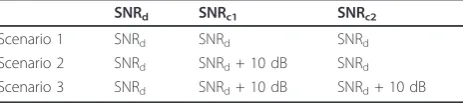
Three propagation scenarios are accounted for, differ-ing in the link SNRs mentioned above for the schemes with two relays cooperating, as shown in Table 2. In scenario 1, we assume that all the links have the same quality conditions, i.e., SNRd= SNRc1 = SNRc2. We also
include scenarios where the second-hop cooperative
0 5 10 15 20
10−7
10−6 10−5 10−4
10−3 10−2 10−1
100
Eb/N0 (dB) Pb
Simulation Theoretical
L=3
NR=1 L=2
N
R=1
L=2
NR=2
Figure 7Theoretical and simulated error probability for data-PRA schemes.
Table 2 Propagation scenarios considered in Monte Carlo simulations forL= 2
SNRd SNRc1 SNRc2
Scenario 1 SNRd SNRd SNRd
Scenario 2 SNRd SNRd+ 10 dB SNRd
links, i.e., RN1® UT and RN2®UT, have higher
qual-ity than the direct link. The choice of these scenarios derives from the fact that, in most real situations, the cooperative link has better quality conditions of trans-mission than the direct link. We then define scenario 2,
where the link between RN1 and UT has a SNR 10 dB
higher than the other two links, i.e., SNRd= SNRc2 and
SNRc1 = SNRd + 10 dB. In scenario 3, all the
coopera-tive paths have better transmission quality conditions than the DP, i.e., SNRc1 = SNRc2 = SNRd+ 10 dB.
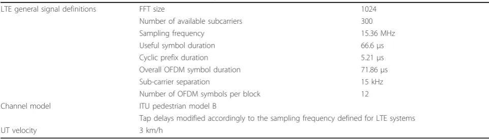
We consider a typical pedestrian scenario based on LTE specifications, following the system configurations in Table 3[31]. In systems where a space-frequency code is needed for two transmitting antennas, the well-known Alamouti coding is implemented [32]. For the three antennas case, the distributed quasi-orthogonal SFBC (QO-SFBC) implemented is the one proposed by Li, Park and Kim (LPK) [33]. In systems with four antennas transmitting simultaneously, we implement the QO-SFBC proposed by Tirkkonen, Boariu and Hottinen (TBH) in a distributed manner [34].
The schemes considered in our evaluation are pre-sented in the list below. The first two bullets correspond to the proposed schemes and the remaining schemes are used as references:
■RA scheme with the proposed algorithm, using
pre-coded QPSK symbols and Viterbi decoding method, for two relays with one and two antennas (PRA 2RN-NB× 1 × 1 and PRA 2RN-NB× 2 × 1, respectively);
■RA scheme with the precoded algorithm, for three
RNs, each one equipped with one antenna (PRA 3RN-NB× 1 × 1);
■Distributed RA (DRA) scheme for two relays, with
one and two antennas, using an SFBC and 16-QAM
modulation (DRA 2RN-NB× 1 × 1 and DRA
2RN-NB× 2 × 1, respectively) [34];
■ DRA scheme, using a QO-SFBC applied to three
relays, with 16-QAM modulation (DRA 3RN-NB× 1
× 1) [33];
■Non-cooperative 4 × 1 QPSK with a QO-SFBC
with a continuous link available (NRA QO-SFBC 4 × 1) [34];
■Non-cooperative 2 × 1 QPSK Alamouti coding
with a continuous link available (NRA 2 × 1).
We also obtain numerical results assuming non error-free links for BS à RNs channels. In this case we assume 2 × 1 space-frequency block coding scheme from BS to each RN.
The numerical results are presented in terms of the average BER as a function of Eb/N0, where Eb is the
received energy per bit at the UT through the direct
link (BS à UT) and N0 is the noise power spectral
density.
6.2. Single-antenna two-relay scheme
Cooperative and reference systems performances are shown in Figure 8 for scenario 1, for the case of the two relays are cooperating with the RA schemes, each equipped with a single antenna. In this case, the refer-ence systems presented are the non-cooperative NRA 2
× 1 and DRA NB × 1 × 1 ones, both using Alamouti
code.
When comparing the PRA scheme against DRA, we observe an improvement of 2.2 dB, for BER = 10-3. This, in turn, derives from the precoding used in the pro-posed scheme, which mitigates some of the penalty resulting from the half-duplex constraint at the relays, avoiding the use of a higher modulation order.
The proposed cooperative scheme has a penalty of about 1 dB from the best reference, i.e., 2 × 1 QPSK Alamouti coding with a continuous link available, for the same BER conditions. It is, however, worthwhile to point out that in our reference we assume independence between the channels. In practice, using co-located antennas inevitably leads to some correlation between the channels, in fact reducing such 1 dB of penalty, or even outperforming it in the case of high correlation [35].
Table 3 Parameters of simulated scenarios according to LTE standard
LTE general signal definitions FFT size 1024
Number of available subcarriers 300
Sampling frequency 15.36 MHz
Useful symbol duration 66.6μs
Cyclic prefix duration 5.21μs
Overall OFDM symbol duration 71.86μs
Sub-carrier separation 15 kHz
Number of OFDM symbols per block 12
Channel model ITU pedestrian model B
Tap delays modified accordingly to the sampling frequency defined for LTE systems
In Figure 9, the performance of the same schemes in scenario 2 is shown. Under this scenario conditions, the proposed precoded scheme outperforms the equivalent non-cooperative system. Improvements of 4 dB are obtained in comparison with 2 × 1 Alamouti, for BER =
10-3. However, the RA Alamouti scheme is still worse
than the non-cooperative scheme with two antennas in the BS. The coding gain between the precoded scheme and the RA Alamouti is of 6 dB for the same BER con-ditions, which is higher than in the previous scenario. By this, we extrapolate that when we have quality asym-metry in cooperative links, we have more benefits in using the precoded Viterbi scheme than the other pre-sented schemes.
In Figure 10, both links between relays and UT have SNRs 10 dB higher than the direct link (scenario 3). In this case, the cooperative schemes have the same
resulting behavior as in the previous scenarios, although the cooperative schemes achieve better performances, as expected. The difference between non-cooperative 2 × 1 and the PRA schemes is now more than 8 dB, for BER = 10-3 (for best visualization purposes, the non-coopera-tive 2 × 1 curve is not completely shown in the plot). Compared with the DRA using Alamouti, we have an improvement of about 2.2 dB with the proposed code, for BER = 10-3, which is the same difference as in sce-nario 1.
In order to observe the improvement obtained with the proposed algorithm in a more realistic situation, where the first cooperative-hops are not considered as ideal or error-free links, other scenarios are considered. It includes correlation between antenna channels [36] and the links between the BS and the RNs have a qual-ity of transmission 10 dB higher than the direct link, since relays are often selected in such way that at least those links have high-quality and due to the possibility of having multiple antennas at the BS. The other links have the same relations defined for each of the scenarios 1, 2 and 3. The resulting performances are presented in Figure 11. We observe that differences between this case and assuming error-free links until the relays are not significant, differing less than 1.5 dB, for BER = 10-3, independently of the considered scenario.
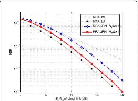
6.3. Two-antenna two-relay scheme
In this sub-section, we assume the two RNs cooperative scheme, with both RNs equipped with two antennas. The considered reference systems are: the non-coopera-tive 2 × 1 and 4 × 1 systems, using Alamouti and TBH codes respectively; and, the RA scheme with the TBH code applied to the RNs. The results shown in Figure 12, were obtained considering that the all the links have
0 5 10 15 20
10−4 10−3 10−2
10−1
Eb/N0 of direct link (dB)
BER
NRA 1x1 NRA 2x1 DRA 2RN−NBx2x1 PRA 2RN−NBx2x1
Figure 8BER of cooperative systems with two single-antenna relays and of reference systems for scenario 1.
0 5 10 15 20
10−3 10−2 10−1
Eb/N0 of direct link (dB)
BER
NRA 1x1 NRA 2x1 DRA 2RN−NBx2x1 PRA 2RN−NBx2x1
Figure 9BER of cooperative systems with two single-antenna relays and of reference systems for scenario 2.
−4 −2 0 2 4 6 8 10 12
10−4 10−3 10−2
10−1
Eb/N0 of direct link (dB)
BER
NRA 1x1 NRA 2x1 DRA 2RN−NBx2x1 PRA 2RN−NBx2x1
the same transmission conditions. In this scenario, higher coding gains are obtained with the proposed algorithm than in Figure 8, as expected, since we have two antennas in each relay. An enhancement of about 5 dB is achieved with the PRA scheme, compared with the distributed cooperative scheme using TBH code, for
BER = 10-3. Comparing with the non-cooperative
sys-tems, the proposed scheme outperforms the NRA 2 × 1 system by about 3 dB, for the same BER. The perfor-mance of the new algorithm also outperform the non-cooperative system 4 × 1 for high SNRs, specifically for Eb/N0 > 9 dB. This happens because, contrarily to the
Alamouti coding, space-time codes for four antennas are not fully orthogonal, thus not achieving full diversity.
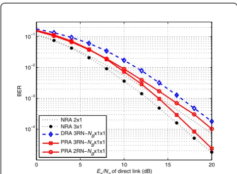
6.4. Single-antenna three-relay scheme
The performance of cooperative schemes with three sin-gle-antenna RNs is also analyzed for a scenario equiva-lent to scenario 1, when all the links have the same transmission quality, in Figure 13. The schemes consid-ered are the RA schemes with the precoded algorithm, for two and three RNs, the DRA with the distributed QO-SFBC LPK and the non-cooperative systems 2 × 1 and 3 × 1, using Alamouti and LPK codes, respectively.
When comparing the PRA scheme against DRA, we
observe an improvement of 2.5 dB for BER = 10-3. This
gain is due to the precoding used in the proposed scheme, which avoids the use of a higher modulation order. More-over the proposed scheme achieves a diversity order of 3, while the SFBC applied to the three relays does not achieve full diversity, since for three transmitting antennas orthogonality is relaxed in order to maintain a unitary rate. The proposed cooperative scheme has a penalty of about 1.3 dB from the best reference, i.e., NRA 3 × 1 scheme with a continuous link available, for the same BER = 10-3. It is however worthwhile to point out that we assume independence between the channels. In prac-tice using co-located antennas inevitably leads to some correlation between the channels, in fact reducing such penalty, or even outperforming it in the case of high correlation [35]. The additional relay brings advantage for moderate/high SNR values. The gain increases with SNR, achieving about 2 dB for BER = 10-4.
Comparing with the DRA, we have the same gain in using the proposed algorithm as in the first scenario. We thus infer that improvements are fixed for the cases where all the cooperative links have the same quality of transmis-sion. We can also observe that the difference between hav-ing two and three RNs in this scenario, in both cases with single-antenna relays, is of 2.2 dB for BER = 10-4.
0 5 10 15 20
10−4 10−3 10−2
10−1
Eb/N0 of direct link (dB)
BER
PRA 2RN−2x1x1 error−free PRA 2RN−2x1x1 non error−free
Scen 2
Scen 3
Scen 1
Figure 11BER of cooperative systems with two single-antenna relays and of reference systems for a scenario with non-ideal first cooperative-hop.
0 5 10 15 20
10−4
10−3
10−2 10−1
Eb/N0 of direct link (dB)
BER
NRA 2x1 NRA 4x1 DRA 2RN−NBx2x1 PRA 2RN−NBx2x1
Figure 12BER of cooperative systems with two relays, each equipped with two antennas per relay, and of reference systems for scenario 1.
0 5 10 15 20
10−4 10−3 10−2
10−1
Eb/N0 of direct link (dB)
BER
NRA 2x1 NRA 3x1 DRA 3RN−NBx1x1 PRA 3RN−NBx1x1 PRA 2RN−NBx1x1
7. Discussion and conclusions
We proposed a data-precoded algorithm for
multiple-antenna L RA based systems, which ensures spatial
diversity, while maximizing spectral efficiency. The algo-rithm mitigates some of the penalty resulting from the half-duplex constraint at the relays and asymptotically achieves the same performance as the one obtained when a direct continuous link is available. Furthermore, with the precoded algorithm, there is no need to trans-mit through the direct link, which is beneficial for most scenarios, since the direct link is usually most strongly affected by path loss or shadowing.
We observed that the gain obtained with the precoded algorithm, relatively to the distributed SFBC one, increases with the number of RNs in a nonlinear way. The proposed precoding brings the performance very close to the one achieved when a direct continuous link is available and SFBC coding is used at the BS. Actually, for the case of two antennas in each relay, the precoded scheme outper-forms the non-cooperative one for high SNR regime, due to the non-orthogonality of space-frequency codes for four transmitting antennas. Improvements are obtained for sce-narios where cooperative links have higher quality than the direct link, being more pronounced as the relative quality of the cooperative links increases.
Moreover, we concluded that independently of the pro-pagation scenario, precoded schemes outperform the equivalent distributed SFBC cooperative schemes, achiev-ing better performance due to the codachiev-ing gain obtained with data-precoding. Even for the most probable situation of asymmetric quality conditions between cooperative links, results show that the proposed scheme is better than the reference cooperative ones. In these cases, the differ-ence between the two cooperative schemes is higher.
We also observed that the extra antenna in each relay leads to a considerable improvement in the overall sys-tem performance. Furthermore, the performance differ-ence between the precoded schemes and the respective equivalent DRA schemes is higher for the case of having two antennas in each relay.
The performance of the PRA scheme was also obtained for three RNs, confirming the previous conclu-sions for two relays. The performance of this scheme, as expected, outperforms that of the scheme with two relays, both with single antennas equipping the relays, especially for scenarios with high-quality links.
From the presented results, it is clear that the proposed cooperative schemes can be used to extend the coverage mainly in scenarios where the quality of the direct link is poor, as is the case of cluttered urban environments. Through the use of the proposed multiple-relay-assisted scheme we achieve full diversity, with a moderate degrada-tion relatively to the case where a continuous link is avail-able, where the number of RNs and antennas in each one can be selected according to the required quality of service.
Appendix 1
In this section, we derive the gains presented in Section 4 obtained with the data-precoded algorithm comparatively with other cooperative algorithms. First we compare the precoded algorithm with the distributed SFBC one, neglecting the non-achievement of full orthogonality requirement for the cases of more than two antennas in all the relays. In these algorithms a 16-QAM modulation is used to implement such algorithm, due to the two phases of communication: in the first one the source broadcasts its information to the relays and in the second one the relays forward that information to the UT using the QO-SFBC. The difference in having two antennas at the RNs instead of one is in the modulation used, since we need the double of the time. In alternative, we could use a DSFBC designed for 2Ltransmitters, maintaining the same modu-lation. According to this, the squared minimum distance expression for the precoded algorithm is given by
dminRA - SFBC2≈
d2 min16 - QAM
NRL L−1
i=0
gNR,i,k, (A:1)
where the variable with the equivalent link channel gain is given by
gj,i,k=
+
hru i1,k2 ,j= 1
hru i1,k
2
+hru i2,k
2
, j= 2 . (A:2)
The ratio between the minimum distance of anM
-QAM modulation and of a QPSK modulation is given by
αM−QAM=
dminM−QAM
dminQPSK
=
3log2M
2(M−1), (A:3)
which we call normalization factor forM-QAM
mod-ulation [29]. The corresponding gains expressed in Equation (A.1) are thus transformed into
dminRA - SFBC2≈d2minQPSK
2 5L
L−1
i=1
ρmi+ 1
gNR,1,k. (A:4)
The asymptotic lower power gain from the proposed algorithm considered relatively to the SFBC is obtained through the ratio of the minimum distances of both algorithms in Equations (8) and (A.4), and by using (A.3), what results in
GL≈10 log
⎛ ⎜ ⎜ ⎜ ⎜ ⎜ ⎜ ⎜ ⎜ ⎝
1
L−1
i=0
4i
L−1
i=1
4iρmi+ 1
2 5LNR
L−1
i=1
ρmi+ 1
⎞ ⎟ ⎟ ⎟ ⎟ ⎟ ⎟ ⎟ ⎟ ⎠
We can consider L−1 i=0 4
i as a sum of the firstLterms
of a geometric progression of ratio 4 and initial value 1. Thus, the gain forLÎN\{1} andNRÎ {1,2} is given by
Equation (9), where the channel gainsrmiare exhibited
in Equation (5) for the case of a single-antenna relays and in Equation (7) for the two-antenna case.
An alternative scheme for comparison with the pro-posed one is the equivalent DCA algorithm. In this
algo-rithm the modulation used is MA-QAM, where
MA= 4
L
2+1 if the number of relays is even and
MA= 4
L+ 3
2 otherwise. WhenNR= 2 the modulation
used is given byMA = 4L. The squared minimum
dis-tance for the DCA algorithm, obtained by application of Euclidean distance definition, is then given by
dminRA - DCA2=
α2
MA−QAM 2
L−1
i=0
gNR,i,k. (A:6)
The corresponding gain in dBs obtained with the pre-coded algorithm in comparison with the equivalent DCA algorithm is given by
GL= 10 log
⎛ ⎜ ⎜ ⎜ ⎜ ⎜ ⎜ ⎜ ⎜ ⎝ 1
L−1
i=0
4i
L−1
i=1
4iρ mi+ 1
α2
MA−QAM 2
L−1
i=1
ρmi+ 1
⎞ ⎟ ⎟ ⎟ ⎟ ⎟ ⎟ ⎟ ⎟ ⎠
. (A:7)
By replacing the modulation factor gain and after some simplifications, we get the final expression for the gain obtained when using the precoded algorithm instead of the DCA one, forLÎN\{1}, and is given by
GL=
⎧ ⎪ ⎪ ⎪ ⎪ ⎪ ⎪ ⎪ ⎪ ⎪ ⎪ ⎪ ⎪ ⎪ ⎪ ⎪ ⎪ ⎪ ⎪ ⎪ ⎪ ⎪ ⎪ ⎪ ⎪ ⎪ ⎪ ⎪ ⎪ ⎪ ⎪ ⎪ ⎪ ⎪ ⎪ ⎪ ⎪ ⎪ ⎪ ⎪ ⎪ ⎨ ⎪ ⎪ ⎪ ⎪ ⎪ ⎪ ⎪ ⎪ ⎪ ⎪ ⎪ ⎪ ⎪ ⎪ ⎪ ⎪ ⎪ ⎪ ⎪ ⎪ ⎪ ⎪ ⎪ ⎪ ⎪ ⎪ ⎪ ⎪ ⎪ ⎪ ⎪ ⎪ ⎪ ⎪ ⎪ ⎪ ⎪ ⎪ ⎪ ⎪ ⎩ 10 log ⎛ ⎜ ⎜ ⎜ ⎜ ⎜ ⎜ ⎜ ⎜ ⎜ ⎜ ⎜ ⎜ ⎝ 1 4L−1
L−1
i=1 4iρ
mi+ 1
(L+ 2)
4
⎛ ⎝4
L
2+1−1
⎞ ⎠
L−1
i=1ρmi + 1 ⎞ ⎟ ⎟ ⎟ ⎟ ⎟ ⎟ ⎟ ⎟ ⎟ ⎟ ⎟ ⎟ ⎠
,Lis even∧NR= 1
10 log ⎛ ⎜ ⎜ ⎜ ⎜ ⎜ ⎜ ⎜ ⎜ ⎜ ⎜ ⎜ ⎜ ⎝ 1 4L−1
L−1
i=1 4iρ
mi+ 1
(L+ 3)
4
⎛ ⎝4
L+ 3
2 −1
⎞ ⎠
L−1
i=1
ρmi+ 1
⎞ ⎟ ⎟ ⎟ ⎟ ⎟ ⎟ ⎟ ⎟ ⎟ ⎟ ⎟ ⎟ ⎠
,Lis odd∧NR= 1
10 log ⎛ ⎜ ⎜ ⎜ ⎝ 1 4L−1
L−1
i=1 4iρ
mi+ 1
3L
24L−1
L−1
i=1
ρmi+ 1
⎞ ⎟ ⎟ ⎟ ⎠,NR= 2
Appendix 2
Theoretical expressions for BER for the schemes shown in Figure 7 are obtained through the general expression in Equation (18), resulting in the following
Pb= ⎧ ⎪ ⎪ ⎪ ⎪ ⎪ ⎪ ⎨ ⎪ ⎪ ⎪ ⎪ ⎪ ⎪ ⎩ 1 2
1−4
3
, γ
1 +γ+
1 3
, γ
4 +γ
,L= 2∧NR= 1 1
2− 4 9
, γ
2 +γ
2 3+
1 2 +γ
−1
18
, γ
8 +γ
11
3+ 4 8 +γ
,L= 2∧NR= 2 1
2
1−64
45
, γ
1 +γ+
4 9
, γ
4 +γ−
1 45
, γ
16 +γ
,L= 3∧NR= 1 (B:1)
The error probability expression for high SNR regime, for the same schemes, reached by Equation (20), are represented by Pb= ⎧ ⎪ ⎪ ⎪ ⎪ ⎨ ⎪ ⎪ ⎪ ⎪ ⎩ 3 4γ
−2,L= 2∧NR= 1
35 16γ
−4,L= 2∧NR= 2
10γ−3,L= 3∧NR= 1
, (B:2)
from where it is evident the diversity order achieved by each scheme.
Competing interests
The authors declare that they have no competing interests.
Received: 23 August 2011 Accepted: 7 February 2012 Published: 7 February 2012
References
1. FHP Fitzek, MD Katz, inCooperation in Wireless Networks: Principles and Applications, (Springer, Dordrechi, The Netherlands, 2006)
2. M Dohler,Virtual Antenna Arrays, (King’s College London, London, UK, 2003). Ph.D. Thesis
3. RU Nabar, H Bolcskei, FW Kneubuhler, Fading relay channels: performance limits and space-time signal design. IEEE J Sel Areas Commun.22(6), 1099–1109 (2004). doi:10.1109/JSAC.2004.830922
4. A Sendonaris, E Erkip, B Aazhang, User cooperation diversity–Part I: system description. IEEE Trans Commun.51(11), 1927–1938 (2003). doi:10.1109/ TCOMM.2003.818096
5. JN Laneman, DNC Tse, GW Wornell, Cooperative diversity in wireless networks: efficient protocols and outage behaviour. IEEE Trans Inf Theory.
50(12), 3062–3080 (2004). doi:10.1109/TIT.2004.838089
6. M Yuksel, E Erkip, Diversity-multiplexing tradeoff in multiple-antenna relay systems, inProc of International Symposium on Information Theory, (Seattle, USA, July, 2006), pp. 1154–1158
7. H Muhaidat, M Uysal, Cooperative diversity with multiple-antenna nodes in fading relay channels. IEEE Trans Wirel Commun.7(8), 3036–3046 (2008) 8. GC Alexandropoulos, A Papadogiannis, K Berberidis, Performance analysis of
cooperative networks with relay selection over Nakagami-m fading channels. IEEE Signal Process Lett.17(5), 441–444 (2010)
9. Q Vien, L Tran, E Hong, Distributed space-time block code over mixed Rayleigh and Rician frequency-selective fading channels. EURASIP J Wirel Commun Netw (2010). Article ID 385872, 9 (2010)
10. G Amarasuriya, M Ardakani, C Tellambura, Output-threshold multiple-relay-selection scheme for cooperative wireless networks. IEEE Trans Veh Technol.
59(6), 3091–3097 (2010)
11. S Teodoro, A Silva, JM Gil, A Gameiro, Distributed space-time code using precoding for cellular systems, inProc of 72nd IEEE Vehicular Technology Conference (VTC’10), (Ottawa, Canada, 2010), pp. 1–5
12. Y Jing, B Hassibi, Distributed space time coding in wireless relay networks. IEEE Trans Wirel Commun.5(12), 3524–3536 (2006)
14. D Sreedhar, A Chockalingam, S Rajan, Single-symbol ML decodable distributed STBCs for partially-coherent cooperative networks, inProc of IEEE International Symposium on Information Theory (ISIT’08), (Toronto, Canada, 2008), pp. 1029–1033
15. J Harshan, BS Rajan, High-rate, single-symbol ML decodable precoded DSTBCs for cooperative networks. IEEE Trans Inf Theory.55(5), 2004–2015 (2009)
16. S Teodoro, A Silva, JM Gil, A Gameiro, Capacity comparison between Alamouti and cooperative VAA with EF and AF relays, inProc of ICT-Mobile Summit 2008 - 17th International Conference on Telecommunications, (Stockholm, Sweden, 2008), pp. 1–8
17. GS Rajan, BS Rajan, A non-orthogonal distributed space-time coded protocol, Part-I: signal model and design criteria, Proc of IEEE Information Theory Workshop (ITW’06), (Chegdu, China, 2006), pp. 385–389 18. GM Kraidy, N Gresset, JJ Boutros, Coding for the non-orthogonal
amplify-and-forward cooperative channel, Proc of IEEE Information Theory Workshop (ITW’07), (Lake Tahoe, California, 2007), pp. 626–631 19. S Teodoro, A Silva, JM Gil, A Gameiro, Novel precoded relay-assisted
algorithm for cellular systems. EURASIP J Wirel Commun Netw (2010). Article ID 414657, 10 (2010)
20. X Tang, Y Hua, Optimal design of non-regenerative MIMO wireless relays. IEEE Trans Wirel Commun.6(4), 1398–1407 (2007)
21. BK Chalise, L Vandendorpe, MIMO relay design for multipoint-to-multipoint communications with imperfect channel state information. IEEE Trans Signal Process.57(7), 2785–2796 (2009)
22. D Zhang, Y Wang, J Lu, QoS aware relay selection and subcarrier and power allocation in cooperative OFDM systems. IEEE Commun Lett.14(4), 294–296 (2010)
23. AJ Viterbi, Error bounds on convolutional codes and an asymptotically optimum decoding algorithms. IEEE Trans Inf Theory.13(2), 260–269 (1967) 24. KJR Liu, AK Sadek, W Su, A Kwasinski,Cooperative Communications and
Networking, (Cambridge University Press, New York, 2009)
25. S Teodoro, A Silva, JM Gil, A Gameiro, Virtual MIMO schemes for downlink space-frequency coding OFDM systems, inProc of PIMRC’09 - IEEE 20th Personnal, Indoor and Mobile Radio Communications, (Tokyo, Japan, 2009), pp. 1322–1326
26. V Tarokh, H Jafarkhani, A Calderbank, Space time block codes from orthogonal design. IEEE Trans Inf Theory.45(5), 1456–1467 (1999). doi:10.1109/18.771146
27. MK Simon, MS Alouini,Digital Communication Over Fading Channels, 2nd edn. (Wiley-Interscience, New Jersey, 2005)
28. A Glavieux,Channel Coding in Communication Networks–From Theory to Turbo Codes, (ISCTE, London, UK, 2007). Digital Signal and Image Processing Series
29. A Goldsmith,Wireless Communications, (Cambridge University Press, New York, 2005)
30. IS Gradshteyn, IM Ryzhik, A Jeffrey, D Zwillinger,Table of Integrals, Series, and Products, 6th edn. (Academic Press, London, UK, 2000)
31. Generation Partnership Project; Technical Specification Group Radio Access Network; Evolved Universal Terrestrial Radio Access (E-UTRA);LTE Physical Layer - General Description, (3GPP, Sophia Antipolis, France, 2007). 3GPP TS 36.201 V8.1.0, 3rd
32. SM Alamouti, A simple transmit diversity technique for wireless communications. IEEE J Sel Areas Commun.16(8), 1451–1458 (1998). doi:10.1109/49.730453
33. J Li, U Park, S Kim, An efficient rate one STBC scheme with 3 transmit antennas, inProc of 4th International Conference on Wireless
Communications, Networking and Mobile Computing (WiCOM’08), (Dallian, China, 2008)
34. O Tirkkonen, A Boariu, A Hottinen, Minimal non-orthogonality rate 1 space-time block code for 3+Tx antennas, inProc of 6th IEEE International Symposium on Spread-Spectrum Techniques and Applications (ISSSTA 2000), (New Jersey, USA, 2000), pp. 429–432
35. S Teodoro,Distributed Coding for Systems with Cooperative Diversity, (University of Aveiro, Aveiro, Portugal, 2011). Ph.D. Thesis
36. D Castelain, V Bota, M Varga, MP Stef, Structure and calibration of the simulation chain.Internal Note of Codiv Project(2008)
doi:10.1186/1687-6180-2012-22
Cite this article as:Teodoroet al.:Data-precoded algorithm for
multiple-relay-assisted systems.EURASIP Journal on Advances in Signal
Processing20122012:22.
Submit your manuscript to a
journal and benefi t from:
7Convenient online submission
7Rigorous peer review
7Immediate publication on acceptance
7Open access: articles freely available online
7High visibility within the fi eld
7Retaining the copyright to your article