LEABHARLANN CHOLAISTE NA TRIONOIDE, BAILE ATHA CLIATH TRINITY COLLEGE LIBRARY DUBLIN OUscoil Atha Cliath The University of Dublin
Terms and Conditions of Use of Digitised Theses from Trinity College Library Dublin Copyright statement
All material supplied by Trinity College Library is protected by copyright (under the Copyright and Related Rights Act, 2000 as amended) and other relevant Intellectual Property Rights. By accessing and using a Digitised Thesis from Trinity College Library you acknowledge that all Intellectual Property Rights in any Works supplied are the sole and exclusive property of the copyright and/or other I PR holder. Specific copyright holders may not be explicitly identified. Use of materials from other sources within a thesis should not be construed as a claim over them.
A non-exclusive, non-transferable licence is hereby granted to those using or reproducing, in whole or in part, the material for valid purposes, providing the copyright owners are acknowledged using the normal conventions. Where specific permission to use material is required, this is identified and such permission must be sought from the copyright holder or agency cited.
Liability statement
By using a Digitised Thesis, I accept that Trinity College Dublin bears no legal responsibility for the accuracy, legality or comprehensiveness of materials contained within the thesis, and that Trinity College Dublin accepts no liability for indirect, consequential, or incidental, damages or losses arising from use of the thesis for whatever reason. Information located in a thesis may be subject to specific use constraints, details of which may not be explicitly described. It is the responsibility of potential and actual users to be aware of such constraints and to abide by them. By making use of material from a digitised thesis, you accept these copyright and disclaimer provisions. Where it is brought to the attention of Trinity College Library that there may be a breach of copyright or other restraint, it is the policy to withdraw or take down access to a thesis while the issue is being resolved.
Access Agreement
By using a Digitised Thesis from Trinity College Library you are bound by the following Terms & Conditions. Please read them carefully.
ST M stu d y o f th e (001) and (110)
surfaces o f m a gn etite
A thesis subm itted to the University of Dublin, Trinity College,
in application for the degree of Doctor in Philosophy
by
Sergio F. C eb allos
Physics D epartm ent
Trinity College Dublin
I
D eclaration
This thesis is submitted by the undersigned for the degree of Doctor in
Philosophy at the University of Dubhn.
It has not been subm itted as an exercise for a degree at any other university.
Apart from the advice, assistance and joint effort mentioned in the
acknowledgements and in the text, this thesis is entirely my own work.
I agree th at the library may lend or copy this thesis freely on request.
n
A ck n ow led gem en ts
II
Firstly, I would like to thank my supervisor Prof. I.V. Shvets giving me
the opportunity to work in the Nanomag Group for the last four years. He
introduced me to the field of surface science, nanotechnology and Scanning
Tunneling Microscopy, always providing excellent guidance during my stud
ies. W ithout his support, encouragement, enthusiasm and determination, this
work would not have been possible.
Ill
group who have moved on other directions such as Dr. Maina Karsanova for
the AGFM/VSM characterization of MnNi samples. Anselm Gademann who
could fix anything computer related and William Signac for his friendship and
dinner parties. I also have to mention other ’’extra-official” members such as
Gregory Cabailh who shared with me the amazing story of the ” funny” trick
and the unforgettable trip through the ’’Valley of silence” .
The group could not operated without the efforts and background sup
port of other members of the Physics Department namely John Kelly, Mick
Reilly, Ken Concannon, Joe McCauley, P at Flanagan, James Kavanagh,
Kevin Thompson and all the secretarial staff, Michelle Duffy, Susan Priest
and Elaine O ’Malley.
Thanks to my friends in Santander, Luis, Jose, David and specially Rafa
for still being part of my life. Friends in Ireland, Marie for those lovely meals
and ” frustrating” clubbing nights we have shared together. Mr. McSweeney
for being a good friend and letting me stay in his house for a cheap rent in
’’Sarajevo” . M att for mutual support in tough moments. Thanks to Ana who
showed me Ireland 10 years ago. Special mention to Patrick Gaffney, for his
his excellent friendship, exceptional advice and the good times during the
thousand ’’nites” out in Dublin.
IV
A bstract
In this thesis the surface of single crystals and thin films of magnetite
(001) and (110) have been studied by scanning tunneling microscopy (STM),
scanning tunneling spectroscopy (STS), Auger electron spectroscopy (AES)
and low-energy electron diffraction (LEED). The use of STM tips made of
magnetic materials is highlighted in this work. A novel technique has been de
veloped by the author in order to provide STM tips made of paramagnetic,
ferromagnetic and antiferromagnetic materials. Special emphasis has been
placed on the study and characterization of tips made of antiferromagnetic
MnNi alloy. Chemical and magnetic characterization has been performed
by AES, X-ray diffraction (XRD), alternating gradient force magnetometer
(AGEM) and transmission electron microscope (TEM). Scanning electron
microscope (SEM) has also been employed for characterization of the tips.
The potential of the MnNi tips for SP-STM measurements has been con
firmed by STS/STM studies of Mn/Fe(001), a test sample whose magnetic
properties are well known. These tips are routinely used by the group for
SP-STM experiments on magnetite.
A detailed analysis of the nature and topography of contam inant free
and contaminated m agnetite (001) single crystals and thin films is given.
It has been dem onstrated how the surface topography of a contaminated
and clean surface of m agnetite (001) is intimately related to the preparation
conditions, with the 0 /E e ratio playing a crucial role in determining the
surface terminations of magnetite.
V
ions surrounded by oxygen ions. A ( \/ 2 x \/2 )/? 4 5 ° surface reconstruction has been observed on a clean m agnetite (001) surface. A high exposure of the surface to oxygen during preparation leads to an octahedral term inated surface. On the other hand, the light exposure of the surface to a hydrogen atmosphere leads to a co-existence of tetrahedral and octahedral term inated surfaces. A combined tetrahedral and octahedral term ination has been rarely observed in the past.
Continuous anneahng of the single crystals and m agnetite thin films leads to a contam inated (001) m agnetite surface. T he typical contam inants found were calcium and potassium . Self assembled patterns of rows and nan otrenches on the surface are observed and explained in terms of the formation of a C a i_ iF e2+ i0 4-like and Mgi_j;Fe2+ i0 4-like phases. A range of different surface reconstructions have been observed w ith increase of the annealing time, related to a variation of the local [0 /F e] stoichiom etry ratio at the surface and the concentration of contam inants, p ( l x l ) , p ( l x 2 ) , p ( l x 3 ) and p ( l x 4 ) superlattices have been found on the Fe3 0 4 (001) surface.
VI
P u b lication s
1. Journals
C. Daul, S. Fernandez-Ceballos, I. Ciofini, C. Rauzy and C. Sclilapfer.
” A novel D ensity Functional Study of th e G round S tate Properties of a
Localized Trinuclear Copper (II,II,III) Mixed-Valence System” .
Chem. Eur.
J., 4392-4401 8 19 (2002)
S. F. Ceballos, G. M ariotto, S. M urphy, I.V. Shvets. ’’Fabrication of magnetic
STM probes and their application to studies of the Fe
3 0 4(001) surface” .
Surf. Sci., 131-140 523 (2003)
G. M ariotto, S. F. Ceballos, S. M urphy, and I. Shvets. ’’Scanning Tunneling
microscopy studies of the Fe
3 0 4(001) surface using antiferrom agnetic
probes” .
J. Appl. Phys., 93 10 (2003)
S.F. Ceballos., G. M ariotto, K. Jo rd an , S. M urphy and I. Shvets. ” An atomic
scale study of the Fe
3 0 4(001) surface” .
Surf. Sci., 548 106-116 (2004)
G. M ariotto, S. F. Ceballos, S. M urphy and I. Shvets. ’’Alkaline and
alkaline-earth m etals self-assembled n an o -p attern s on th e Fe
3 0 4(001)
surface” .
Phys. Rev. B
70, 035417 (2004)
VI]
K. Jordan, G. M ariotto, S. F. Ceballos, S. M urphy and I. Shvets. ’’Spin
Polarised scanning tunnehng microscopy of Fe
3 0 4(001) charged ordered
surface” .
Submitted: Surf. Sci.,
Aug (2004)
K. Jordan, G. M ariotto, S. F. Ceballos, S. M urphy and I. Shvets. ’’Atomic
scale SPSTM imaging of the Fc
3 0 4(001) surface using antiferrom agnetic
tips” .
Accepted: J. Mag. Mag. M at.,
Sep (2004)
S. Murphy, S. F. Ceballos, G. M ariotto, N. Berdunov, K. Jordan, and
I. Shvets. ’’Atomic scale spin-dependent scanning tunneling microscopy
using antiferrom agnetic STM tip s” .
In press: J. Microsc. R. Tech.,
Sep (2004)
S.F. Ceballos, K. Jordan, G. M ariotto, N. Berdunov, S. M urphy and I.V.
Shvets. ” Surface studies of m agnetite (110)” .
In preparation
2. C o n fe r en ce P r o c e d in g s
S. F. Ceballos, K. Jordan, S. M urphy, C. Seoighe, and I. V. Shvets. "C on
tam inan ts Induced Onset of N anostripes and N anotrenches on th e Fe
3 0 4(001) Surface” .
A IP Conf. Proc.,
696, 879 (2003)
G. M ariotto, K. Jordan, S. F. Ceballos, S. M urphy, C. Seoighe, and I. V.
Shvets. ” C harge O rdering on th e (\/2 x -\/2)i?45° R econstructed Fea
0 4(001)
Surface” .
A IP Conf. Proc.,
696, 873 (2003)
v;ii
V. Shvets. ’’Polaronic Superlattice Form ed on Oxidised M agnetite (111)
Surface” .
A I P Conf. Proc.,
696, 865 (2003)
S. F. Ceballos, G. M ariotto, N. Berdunov, S. Murphy, K. Jordan, and I. V.
Shvets. ’’Fabrication of M agnetic Probes for Spin-Polarized STM Studies of
th e Fe3 0 4
(001) and (111) Surfaces”
A I P Conf. Proc.,
696, 298 (2003)
IX
List o f a b b rev ia tio n s
ID - one dimensional
2D - two dimensional
3D - three dimensional
AES - Auger electron spectroscopy
AGFM - Alternating gradient force magnetometer
CMA - cylindrical mirror analyser
DLA - diffusion limited aggregation
DOS - density of states
e-beam - electron beam
EGG - electrostatic centre of gravity
HT - liigh-temperature
L - Langmuir
LBL - layer-by-layer
LDOS - local density of states
LEED - low energy electron diffraction
LT - low-temperature
LTSTM - low-temperature scanning tunneling microscopy
MBE - molecular beam epitaxy
ML - monolayer
RT - room tem perature
K
SPM - scanning probe microscopy
SPSTM - spin polarised scanning tunneling microscopy
STM - scanning tunneling microscopy
STS - scanning tunneling spectroscopy
TEM - transmmission electron microscope
TMR - tunneling magneto resistance
TPD - tem perature programmed desorption
TSP - titanium sublimation pump
UHV - ultra high vacuum
List o f Figures
2.1
Schematic diagram of the process of Auger emission in a sohd
5
2.2 Schematic representation of a STM tunnehng junction . . . .
8
2.3
The m ultidisciphnary n atu re of iron oxide research
... 15
2.4
Phase diagram for the Fe — O system ... 17
2.5
Unit cell of Fe
3 0 4... 18
2.6
The (001) B -term inated surface of Fe
3 0 4... 20
2.7
The (001) A -term inated surface of Fe
3 0 4... 21
2.8
Fe
3 0 4(110)
A
and
B
term inated s u r f a c e ... 22
2.9
Representation of the charge neutrality of m agnetite (001) . .
25
3.1
Top view of the UHV system
... 32
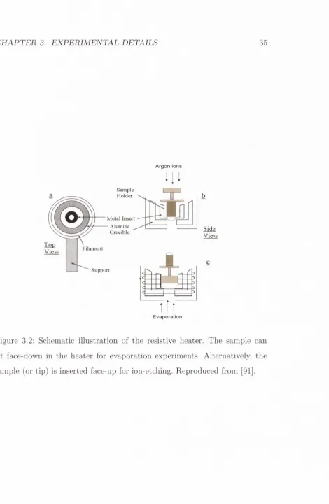
3.2
Schematic of the resistive h e a t e r ... 35
3.3
Schematic illustration of th e e-beam h e a t e r ...36
3.4
Schematic illustration of a STM h e a d ... 40
3.5
Schematic of four-grid optics in LEED m o d e ...42
3.6
Schematic of LEED screen geom etry ...43
4.1
electrochemical set up ... 47
4.2
etching p r o c e s s ... 48
4.3
MnNi structure and m agnetic o r d e r ... 51
4.4
X-ray diffraction s p e c t r u m ... 52
L IS T OF FIGURES
XII
4.5
MnNi SEM i m a g e s ... 54
4.6 G eneral m agnetic behaviour for magnetic m a t e r i a l s ... 56
4.7 m agnetisation versus external magnetic field for a MnNi sam-
p le(etch ed /n o t e t c h e d ) ... 57
4.8 X-ray diffraction spectra c o m p a r i s o n ... 59
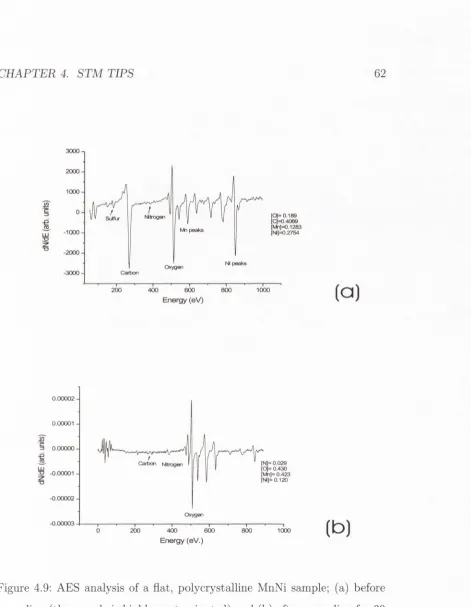
4.9 AES analysis of a MnNi
sample 1 ... 62
4.10 AES analysis of a MnNi
sample 2 ...63
4.11 M agnetic contrast w ith a MnNi p r o b e ... 67
4.12 m agnetisation orientation schematic for F e /W and MnNi tips . 68
4.13 SEM image of a C r t i p ... 71
4.14 SEM image of a Ni t i p ... 72
4.15 SEM image of a Fe3 0 4
(001) surface taken w ith a MnNi tip . . 73
5.1
AES and LEED of a clean Fe3 0 4
(001) s u r f a c e ... 79
5.2 STM image, B -term ination surface ... 80
5.3 STM image, B -term ination surface, Z o o m - in ...81
5.4 STM image. A- B- coexisting t e r m in a t io n s ... 84
5.5 STM image. Zoom-in on A - te r m in a tio n s ...85
6.1
Surface reconstructions on m agnetite (001) s u rfa c e ...92
6.2 AES spectrum of low level of contam inants Fc304
(001) surface 93
6.3
O nset of form ation of tr e n c h e s ... 94
6.4
O nset of form ation of trenches. Z o o m - i n ... 96
6.5 T he onset of form ation of p (1 x 3) superlattice by contam inants 97
6.6 A E S /L E E D for a contam inated m agnetite (001) surface . . . . 99
6.7 Different surface rearrangem ents on the surface
... 100
6.8
p ( l
X2) surface reconstruction...102
L I S T OF F IG U R E S
X III
6.10 AES and LEED for a p (l x 3) surface re c o n s tr u c tio n ... 106
6.11 p (l
X3) STM surface reconstruction...107
6.12 p (l
X3) STM surface reconstruction. Z o o m -in ... 108
6.13 p (l
X3) schematic m o d e l ...109
6.14 LEED p a tte rn for a p (l x 4) surface re c o n s tru c tio n ... I l l
6.15 STM image, p (l x 4) surface r e c o n s tr u c tio n ...113
6.16 Models proposed for a p (l x 4) surface re c o n stru c tio n ... 115
6.17 STM image of Fe
3 0 4th in film annealed at low tem p eratu re. . 118
6.18 AES d a ta for a 70 nm contam inated m agnetite th in film . . .1 1 9
6.19 STM image for rounded terrace f o r m a t i o n ... 120
6.20 I/V curves for a contam inated m agnetite 70 nm th in film . . . 121
6.21 STM image of a p ( l x 1) r e c o n s tr u c ti o n ... 122
7.1
LEED p a tte rn for m agnetite (1 1 0 )... 127
7.2
LEED p a tte rn of a m agnetite (110) surface w ith fractional
order s p o ts ...129
7.3
STM image of a m agnetite (110) terraced s u r f a c e ...130
7.4
STM image of a m agnetite (110) nanostructed s u rfa c e ... 131
7.5
STM image of a m agnetite th in film ( 1 1 0 ) ... 133
7.6
Ball model for m agnetite (110) n a n o s tr u c tu r e s ... 135
7.7
I/V curves for m agnetite (110) s u r f a c e ...137
A .l
AES spectrum for a p ( l x 3) surface re c o n s tru c tio n ... 145
B .l Lattice param eters calculation of a p ( l x 3) LEED p a tte rn . . 149
C .l Classification of surfaces according to T a s k e r ...151
List o f Tables
2.1
Properties of iron oxides
C ontents
1
In trod u ction
1
2
B ackground
4
2.1
Introduction to experim ental techniques ...
4
2.1.1 Auger Electron Spectroscopy (A E S )...
4
2.1.2 Scanning Tunneling Microscopy ( S T M ) ...
6
2.1.3 Scanning tunneling spectroscopy ( S T S ) ... 10
2.1.4 Low Energy Electron Diffraction (L E E D )... 12
2.2
M agnetite: Fe
3 0 4... 14
2.2.1 I n tr o d u c tio n ... 14
2.2.2 The surface of Fe
3 0 4( 0 0 1 ) ... 19
2.2.3 The surface of m agnetite (110)
... 19
2.2.4 A utocom pensated s u r f a c e s ... 23
2.2.5 L iteratu re r e v i e w ...26
3
E xp erim en tal d eta ils
31
3.1
The ultrahigh vacuum set u p ... 31
3.2 The preparation c h a m b e r... 33
3.2.1 The resistive h e a t e r ... 34
3.2.2 The e-beam h e a t e r ... 36
CONTENTS
XVI
3.2.3
The ion g u n ... 37
3.2.4
Sample Characterization: Auger Electron Spectroscopy
38
3.3
The room -tem perature S T M ... 39
3.3.1 Four-grid L E E D ... 41
4 ST M tip s
44
4.1
In tro d u c tio n ... 44
4.2
Tip fabrication procedure ... 46
4.3
MnNi t i p s ... 50
4.3.1 MnNi alloy ... 50
4.3.2 Tip p re p a ra tio n ... 50
4.3.3 MnNi tips ch aracteriza tio n ... 53
4.3.4 Magnetic contrast: Scanning tunneling spectroscopy
(STS) ... 64
4.4
Cr t i p s ... 69
4.5
Other t i p s ... 70
4.6
STM results on magnetite (001) taken with a MnNi tip . . . . 70
4.7
C o n clu sio n s... 74
5 T he Clean Fe3 0 4
(001) surface
76
5.1
In tro d u c tio n ... 76
5.2
Sample p re p a ra tio n ... 77
5.3
Surface p re p a ra tio n ... 77
5.4
STM results and discussion ... 78
5.4.1 B- temination su rfa c e ... 78
5.4.2 Co-existing A- and B- te rm in a tio n s ... 82
CONTENTS
XVII
6 T h e C on tam in ated Fe3 0 4
(0 0 1
) surface
88
6.1
In tr o d u c tio n ... 88
6.2
Sample p r e p a r a t io n ... 89
6.3
C ontam inated Fe
3 0 4(
0 0 1) s u r f a c e ... 90
6.3.1 Breaking of long range (-\/2 x \/2)i?45° order by the
presence of c o n ta m in a n ts ... 93
6.3.2 p (l
X2) reconstruction
... 98
6.3.3 p ( l
X3) reconstruction
... 104
6.3.4 p (l
X4) surface r e c o n s tr u c tio n ...110
6.4
p ( l X 1 ) ... 122
6.5
C o n c lu s io n s ...123
7 Surface stu d ies o f Fe3 0 4
(110)
125
7.1
In tr o d u c tio n ...125
7.2
Sample p r e p a r a t io n ... 126
7.3
Results and d i s c u s s i o n ... 126
7.3.1
Form ation of n a n o s tr u c tu r e s ... 126
7.3.2 D is c u s sio n ... 132
7.4
C o n c lu s io n s ...138
8 Sum m ary
139
8.1
C o n c lu s io n s ...139
8.2
Further work ... 141
8.2.1
Further characterisation of MnNi p r o b e s ... 141
8.2.2
Further characterisation of Fc
3 04... 142
A A E S calcu lation s
144
C O NT EN T S
XVIII
C hapter 1
In trod u ction
M etal-oxide surfaces have recently draw n increasing atten tio n due to their
im p o rtan t technological applications,
i.e. corrosion, catalysis and microelec
tronics. Iron oxides have also a ttra c te d much interest, in particular Fe
3 0 4,
commonly known as m agnetite, as it is predicted to be half a m etallic ferro-
m agnet [1].
Fes
0 4(001) and (110) artificial and n atu ral single crystal and th in film
surfaces are th e focus of the study presented here. M agnetite is one of the
few oxides w ith very high, almost m etallic conductivity, which is due to
Fe ions of different valence states being located at identical crystallographic
positions. At room tem perature, the electrical conductivity of Fe
3 0 4is about
200
cni“ ^ [2]. M agnetite is also predicted to be a half-metallic ferrim agnet
[1,3], m eaning th a t in th e spin-up sub-band it is a m etal and in the spin-
down sub-band it is an insulator. At a tem p eratu re of 120 K bulk m agnetite
exhibits a m etal-insulator transition, known as th e Verwey tran sitio n [2,4],
a t which its conductivity decreases by two orders of m agnitude [5,6]. The
change of conductivity is accompanied by a change in its crystallographic
structure, whose sym m etry is lowered from cubic to monoclinic. The surfaces
C H APTER 1. INTRO D U CTIO N
2of m agnetite show a highly complex behavior which is due to m any factors
such as, the stoichiometry; i.e. the ratio of th e Fe to O ions on th e to p most
layer [7-9].
A detailed investigation of probes m ade of magnetic m aterials for Scan
ning Tunneling Microscope (STM) and Spin polarised STM (SP-STM ) ap
plication is perform ed in this study. A spects such as fabrication, geom etry
and com position are studied. A reproducible technique for th e fabrication of
STM tips from a range of magnetic m aterials has been developed. The tips
are formed by electrochemical etching in an aqueous solution (NaOH, HCl),
using polym er tubing to physically restrict the active etching region. Tips,
w ith apexes in the 50-100 nm range, have been produced from polycrystalline
MnNi, Cr, Fe and Ni. Atomic resolution STM images have been achieved on
the Fe
3 0 4(001) surface, using MnNi tips.
CH APTE R 1. INTRO D U CTIO N
3Ca and K. A detailed investigation of the self-assembly of impurities onto
the surface is given at a nano- and atomic- scale on both surfaces.
C hapter 2
Background
2.1
In tro d u ctio n to ex p erim en ta l tech n iq u es
2.1.1
A u ger E lectron S p e ctro sco p y (A E S )
Auger Electron Spectroscopy (AES) represents one of the most im portant
chemical surface analysis tool for conducting samples. The method is based
on the excitation of so-called ’’Auger electrons” . AES is based on the use
of primary electrons with typical energies between 3 and 30 keV and the
possibility to focus and scan the primary electron beam in the nanometer
and micrometer range analyzing the top-most atomic layers of m atter. Figure
2.1 shows the sequence of events following ionisation of a core level. For
this example the K level is shown as being ionised by an incident electron,
whose energy Ep must obviously be greater than the binding energy
of
an electron in K. Following the creation of a hole in the level K, the atom
relaxes by filling the hole via a transition from an outer level, in this example
shown as Li. As a result of th at transition the energy difference (E/c — E/,i)
becomes available as excess energy, and this excess energy can be used by
CHAPTER 2. B AC K G R O U N D
5
u
- Vac1 EF I M, etc
L2 .3
Ji
•
---Initial state
Vac 0
EF M, etc L * 2 .3
E
K
K
o-Excitation and
emission
Final state
Vac
1 EF z M, etc
L * 2 .3
- Li
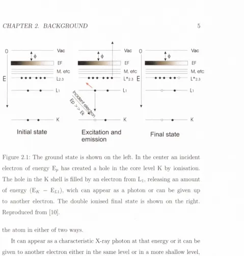
Figure 2.1: The ground sta te is shown on the left. In the center an incident
electron of energy Ep has created a hole in the core level K by ionisation.
The hole in the K shell is filled by an electron from Li, releasing an am ount
of energy
wich can appear as a photon or can be given up
to another electron. The double ionised final state is shown on the right.
Reproduced from [10].
the atom in either of two ways.
[image:26.534.45.524.44.545.2]CH APTER 2. BACKGROUND
6
obtained under electron bombardment with a characteristic energy allowing
one to identify the emitting elements. Auger electrons render information
2.1.2
Scanning Tunneling M icroscopy (ST M )
Comprehensive reviews of the theory and operating principles of scanning
tunneling microscopy (STM) and spectroscopy (STS) are given in dedicated
texts by Chen and Wiesendanger [12,13]. The fundamental theory of STM is
modelled on the quantum-mechanical description of an electron with energy
E travelling in a ID potential U(z) of the form shown in figure 2.2(a). This
electron is described by a wavefunction
ip{z),
which satisfies the Schrodinger
equation:
where m is the electron mass and
h = h/2iT
(where h is Planck’s constant).
In the classically allowed region where E > U(z), this equation has solutions
of the form:
__________
where the electron can move in either the positive or negative direction.
In the classically forbidden 6am'er region where E < U(z), the Schrodinger
equation has the solution:
The
K,
term describes the decay of the electron wavefunction within the bar
rier region. For a finite potential U(z), there is a non-zero probability
P
of
finding the electron at a position z inside the barrier region, which is given
essentially on the elemental composition of the first 2-10 atomic layers [11].
^
+ U{z)^(z) = Eii{z)
(2.1)(2.2)
CH APTER 2. BACKGROUND
7
Consequently, if the width of the tunnel barrier is sufficiently narrow, there
is a finite probability th at the electron can tunnel through the barrier region.
In the tip-vacuum-sample configuration of an STM junction (figure
2.2(b)), the height of the tunnel barrier is determined by the
work func
tion 4>
of the tip and sample (assumed to be identical for convenience), which
is the minimum energy required to remove an electron from the metal to vac
uum. An electron at the tip or sample surface, with Fermi energy
E p = —(f)
eV, will have the greatest opportunity to tunnel through the barrier, since
by definition the
Fermi level denotes the upper limit of electron occupancy
in the metal. In the absence of an externally applied bias, the electron can
tunnel through the barrier in either direction so th at there is no net tunnel
current. By applying an external voltage V, electrons in the sample within
the energy range
Ep — eV < E < Ep have an opportunity to tunnel through
the barrier. If
eV
0, then only electron states very near to the Fermi
level are })robed. The probability for an electron in the nth states to tunnel
through a barrier of width W is given by:
P
a |
-ipniO) p
K, =
(2.5)
Taking all the possible states in the energy range
Ep — eV < E < Ep into
account, the tunnel current is:
h<x
^
I ^(0) p
(2.6)
E = E p —eV
If V is small enough th at the density of electronic states does not vary sig
nificantly within it, the latter sum can be conveniently w ritten in terms of
the
local density o f states (LDOS). At the Fermi level, at a location z and
energy E, the LDOS Ps(z,E) of the sample is defined as:
CH APT ER 2. BACKGROUND
8
U(z)
0
(a)
vacuum level
sample
eV
0
z
[image:29.534.54.519.40.667.2]CHA PTER 2. BACKGROUND
9
for a sufficiently small
e. The LDOS is the number of electrons per unit
volume per unit energy , at a given point in space and at a given energy. The
tunneling current can be conveniently written in terms of the LDOS of the
sample at z=0 and E = E^p:
I t < x V p s { 0 , E F ) e - ^ ' ^ ^ (2.8)
It is clear from this equation that: (1) the tunnel current is directly pro
portional to the bias applied across the junction, (2) it decays exponentially
as the distance between the tip apex and the sample surface is increased.
The significance of the probe-tip LDOS contribution is realised through a
time-dependent perturbation model of metal-insulator-metal tunneling pro
posed by Bardeen [14], Here, a
Transfer Hamiltonian H r
is used to describe
the transfer of a tunneling electron from a sample state
ip to a. tip state
x-
The tunnel current can be taken as a convolution of the sample LDOS
and the tip LDOS
pt-A -rrp /*eV
h = - -
P.{Ef - e V + E)pt{EF - E) \ M
d E
(2.9)
a Jo
It also includes a tunneling m atrix element M, describing the am phtude of
electron transfer across the tunnel barrier (through the overlap of the 'ip
and
X
states). The integral describing M is evaluated over any surface lying within
the barrier region and rate of electron transfer is determined by the Fermi
golden rule [15].
Bardeen and Giaever [14] assumed th at the magnitude of the tunneling
m atrix element | M | does not change appreciably in the interval of interest.
Then, the tunneling current is determined by the convolution of the DOS of
two electrodes:
A qrp r e V
CHA PTER 2. BACKGROUND
102.1.3
S can n in g tu n n e lin g sp e c tro sco p y (S T S )
Equation 2.11 shows th a t the tunnehng current can be expressed as a
convolution of the sample LDOS
Ps
and tip LDOS
pt
(see equation 2.9). In
the semiclassical WKB approximation the tunneling current density between
two planar electrodes can be expressed by:
27TP / \
=
T ( s , V , E ) [ f { E ~ e V ) - f ( E ) Y ! > . ( E ) p ^ ( E - e V ) d E
where s is the tip-sample distance, V is the sample bias voltage, T(s,V,E)
is the tunneling transmission probability,
P s { E )and
P t { E )are LDOS of the
surface and the tip respectively. f(E) is the Fermi-Dirac distribution function.
In scanning tunneling spectroscopy formalism, the first derivative of the
tunneling current is usually analysed:
“
A\eT{s,
\/, B )p .(B )p ,(£ -
e V ) \ ^ „ y +
f
T (s, K
E)i>,(E) ■
J e V
aV
f ~
^
P
‘ (E)P.(E - eV)dE\
(2,12)
J e V
dV
C H A P T E R 2. BACKGROUND
11measurement is known a priori. Otherwise, the sample DOS does not have a
definitive relation to the tunneling spectrum. In equation 2.12, if the second
and third terms are neglected, a constant tip LDOS and a weak voltage
dependence of the tunneling probability are assumed, d l/d V is proportional
to the sample LDOS
P s { E ) .This simple proportionality forms the basis of
the STS and mostly d l/d V measurements are directly compared to calculated
sample densities of states. In order to obtain reproducible tunneling spectra,
the STM tip must have reproducible DOS, preferably flat DOS, th at is,
with a free-electron-metal behavior. Tip DOS are usually highly structured.
Feenstra
et al.
[16] developed an in-situ tip preparation procedure which
causes local melting and recrystallisation of the tip apex. This procedure
results in flattening of the tip DOS allowing one to obtain reproducible STS
d ata with W tips.
From the present discussion it is already clear th at the relation between
d l/d V and the sample LDOS is highly complicated. In the case of a tip with
a more complicated DOS, such as Fe or MnNi tips, this approximation has
to be taken with caution and it might not be so accurate as for the case of
W tips. Nevertheless, reproducible STS results have been obtained with W
coated with Fe tips on the surface of Mn/Fe(110) [17].
CH APTE R 2. BACKGROUND
probability function, T, is given by:
12
T = ts
exp
- 2 s ( ^ ( 4 > + V / 2 ) y '^
+ (,e x p
The first (second) term of T describes tunnehng from the sample(tip)
Fermi level to unoccupied tip(sample) states, t [nA/V] is a proportional
ity coefficient which is related to the tip-surface effective contact area and is
proportional to the sample (for t^) or the tip (for t*) densities of states at the
Fermi level. 0 [eV] is given by the local work function (which is the avarage
of the tip and sample work functions in a first approximation). S [nm] is the
tip-sample distance and m the electron mass. To extract these parameters
from the experimental data, d l/d V should be fitted to T [17,22,23].
2.1 .4
Low E n erg y E lectron D iffraction (L E E D )
A plane wave incident on an atom or atoms within a unit cell will be scattered
in all directions, but interference between waves scattered from neighboring
unit cells will restrict the net flux to those directions in which the scattered
waves from all vmit cells are in phase. This requires th a t the scattered waves
from neighboring cells differ only by an integral number of wavelengths A.
In the simple case of a one-dimensional lattice, the in-phase condition is met
for all integers n which satisfy the condition:
a{sin4>n — sin4>o) = nX
(2-14)
C H APTE R 2. BACKGROUND
13
the lattice plane. This is known as the Laue condition. If the incident and
emergent beams are described by unit vectors
sqand s„ then this can be
w ritten in vector form as:
a ■
{sn —
So) = nX
(2-15)
or
a ■
Asn
=
nX
(2-16)
where
As„ =
- So
(2.17)
The diffracted beams are determined by A s„ and, in the one-dimensional
case, they are given by integral multiples of the basic unit (A / a). This
involves the reciprocal of the real space lattice vector a. We can define a
reciprocal lattice vector a*= (1/a).
For surface diffraction in a 2D system, the electron beam must conserve
both its energy and the component of its momentum parallel to the surface.
k\\^ +
+ k'j_^ ,
k^^ = k\\+ghi
(2.18)
where
k\\ and
kj_ are the parallel and perpendicular momentum compo
nents of the incident beam, while
k'^^
and k'^ are those of the diffracted beam.
The
reciprocal lattice vector Qhi
is related to the beam energy
Eev, electron
mass
rrie
and diffraction angle
a by;
C H A P T E R 2. B A C K G R O U N D
14
where
a* and
b*
are the reciprocal lattice vectors. These are related to
the real space vectors a and
b by [26]:
d.a* = b.b* = 2
tta.b* = b.a* = 0
(2.20)
This shows th e direct correspondance between th e observed diffraction
p a tte rn and th e reciprocal lattice of th e surface. The reciprocal lattice vec
to r
Qhi lies in a direction th a t is orthogonal to th e plane of th e real space
lattice th a t is denoted by th e Miller indices h and 1. The Miller indices of
the diffracting planes are used to index the diffraction spots of th e LEED
p attern .
2.2
M a g n e tite : Fe3 0 4
2 .2.1
I n tr o d u c t io n
CHAPTER 2. BACKGROUND
15Iron Oxides
M edicine - Iron O verload - Polynuclear organic com plexes Biology Biomlnerals Ferritin Navigation Chemistry - sorbents
Oxidants
ndustrial Chemistry
Pigments - Tapes - Catalysts
eochem istr^ Crystal chemistry Redox buffering
- Aggregation Plant nutrient Pedogenesi
ineral Properties Sorbents - Formcmo
iron Oxides
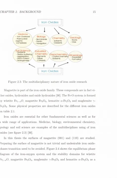
Figure 2.3; The m u ltid is c ip lia n ry nature o f iro n oxide researcli
M a gne tite is p a rt o f the iro n oxide fam ily. These compounds are in fact ei ther oxides, hydroxides and oxide hydroxides [36]. The F e -0 system is form ed by w iis tite Fei_j:0 , m agnetite Fe3 0 4, hem atite a-Fe2 0 3 and m aghem ite 7- Fe2 0 3. Some physical properties are described for the different iro n oxides
on table 2.1.
Iro n oxides are essential for other fundam ental sciences as well as for a wide range o f applications. M edicine, biology, environm ental chemistry,
geology and soil science are examples o f the m ultidiscip lin es using of iro n oxides (see figure 2.3) [36].
In th is thesis the surfaces o f m agnetite (001) and (110) are studied.
Preparing the surface o f m agnetite is not tr iv ia l and undesirable iro n oxide- phases tra n s itio n need to be avoided. Figure 2.4 shows the e q u ilib riu m phase
diagram o f the iron-oxygen system and the s ta b ility dom ains fo r w iis tite
[image:36.534.50.524.47.770.2]CH APTER 2. BACKGROUND
16
M a g n etite
H a em a tite
M agh em ite
W ixstite
Formula
Fe3 0 4
a-Fe2 0 3
7 -F e2 0sFeO
Structural
type
Inverse
spinel
Corundum
Defect
spinel
Defect
NaCl
Crystal system
Cubic
Hexagonal
Cubic/
Tetragonal
Cubic
Space group
0^-Fd3m
D16-R3C
0^-F d3m /
P432i2
0^,Fm 3m
Cell
dimensions
(nm)
a; 0.84
a: 0.50
c: 1.38
a; 0.84/
a: 0.83
c: 2.50
a: 0.43
Colour
Black
Red
Brown
Black
Magnetic order
Ferri-
Weakly
ferro-Ferri-
Antiferro-Curie/Neel
temperature (K)
850
Tv-.
119
956
820-986^1)
203-211
R T Saturation
magnetisation
(J 'T ^K g -^)
92-100
0.3
60-80
Density (gcm^)
5.18
5.26
4.87
5.9
Formula units
per unit cell
8
6
8
4
[image:37.534.55.519.35.748.2]CHAPTER 2. BACKG ROU N D
17
L IQ U ID [RON
1600
5 - IRON 1400
>200
i - I RON
UJ 5 IDOO
y eoo
600
H E M A T I T E
200
-60 -50 -40
LOG P o j (ATM.)
-30 -!0
Figure 2.4: Phase diagram for the Fe — O system. Reproduced from [36]
function of the tem p eratu re and oxygen content.
Bulk Fe
3 0 4has a cubic inverse-spinel structure, where th e 32 0 ^ “ anions
form an face centered cubic (f.c.c.) lattice, half of th e Fe^"*" cations occupy 1/8
of th e available tetrah ed ral sites (64 available A-sites) and th e other half of
the Fe^"*" cations are located in 1/4 of the available octahedral interstices (32
available B-sites). 1/4 sites of the octahedral interstices is occupied by Fe^"^
cations. The unit cell edge constant is a = 0.83963 nm [37]. For stoichiometric
[image:38.534.54.521.37.629.2]C H A P T E R 2. B A C K G R O U N D
18
a
w
a
0 16 octahcdral interstices arc occupied by Fe' and
I'c ions in equal pri)porlions
# S tetrah ed ral in terstices arc o ccu p ied hy Fe
32 ox y g en an io n s form an r.c.c. latticc
Figure 2.5: Unit cell of Fe
3 0 4M agnetite is also predicted to be a half-metallic ferrim agnet [1,19], m ean
ing th a t in th e spin-up sub-band it is a m etal and in the spin-down sub-band
it is an insulator. There is a gap in the m ajority spin band a t th e Fermi
level bu t there is not in the m inority spin band. Filled bands of the m ajority
spin are mainly composed of
3d
levels of Fe in the B site. For th e A site
3d
orbitals of Fe are filled by th e m inority spin electron. Moreover, th e orbitals
ju st below th e Fermi level are composed of 3d levels of Fe in th e B sites [1,38].
Alvarado et al.
have also dem onstrated [38] th a t the electrons from the O 2p
states lie well below th e Fermi energy.
C H AP T E R 2. BACKGROUND
19
has not been fully resolved [41,42]. The transition has been viewed as an
order-disorder transition in relation to the arrangement of cations on the
octahedral sites of the inverse spinel structure whose formal chemical formula
can be w ritten as Fe4
^"*"[Fe^“*'Fe^’'']B0 4
^“ [43-47].
2.2.2
T h e surface o f Fe
3 0 4
(001)
The (001) plane of magnetite can be viewed as a stacking sequence of two
alternating layers. The A-layer contains tetrahedrally coordinated Fe^'*' ions,
while the B-layer is composed of rows of octahedrally coordinated Fe^"^ and
Fe^"'' ions surrounded by oxygen ions. The separation between neighbouring
planes (i.e. the A-B interplanar separation) is 1.05 A, while the separation
between successive like planes (i.e. the A-A or B-B interplanar separation)
is 2.10 A. In each octahedral plane, the nearest-neighbor 5-site cations form
rows th at run along the [110] and [lIO] directions.
The rows in successive octahedral planes are rotated by 90° with respect to
one another, giving these planes a two-fold rotational symmetry. In contrast,
the arrangement of cations in the A-layers give them a four-fold rotational
symmetry. A ball model of Fe3 0 4
(001) is shown in figures 2.6 and 2.7 where
a full
B
and >l-terminated surface are depicted respectively.
2.2.3
T h e surface o f m a g n e tite (110)
The bulk of Fe3 0 4 can be thought to consist of two different planes perpen
dicular to [110] with arrangement of the Fe and O ions as given in figure
2.8.
C H APTER 2. BACKGROUND
20
OoO O
O O
o
c
o o o o
g
Q
OoO OoO
Q
O
'
o o o o
(V2 X V2)R45°
unit cell
0 0 0 Oo
O O
Oo
o
^O O
0 0 0 1 Oo
O
...
(1x1)
unit cell
O
"ITop p la n e : O ctahedral
O
Iron
O
Iron
Tetrahedral p la n e below
CH APTER 2. BACKGROUND
21(V2
X V2)R45°unit cell
O 0.0 ox 0^0
ooo o
‘ vO 0 .0
. o
c
o o
OoO O
0<1©^©4)Q O
o
C)--Q.(|,,|
unit cell
U Iron
Top plane: Tetrahedral
O Oxygen \ o c ta h e d ra l p la n e below
O Iron
^
OoO O
Figure 2.7: The (001) A-terminated surface of Fe
3 0 4. The large circles rep
resent oxygen atoms forming an f.c.c. lattice on the layer below. The small
circles depict iron atoms located at the
A
and
B
sites. The p (l x 1) primi
tive unit cell is marked with an black square. The (-\/2 x \/2)/?45° unit cell
CHAPTER 2. BACKGROUND
226 A
A t e r m i n a t i o n
( -1 1 0)
O
o 6 A Oxygent
B termination1.1 A
o
.c
'
--►
o
c
• (00-1) oo
. € )c
o
• oc
. € )o
€)
•
oC)
. € ) 6 A€)
€)
' , oO
.C
Octahedral Fe
Tetrahedral Fe
o o o o
o
o
o
o
o
o
Q
o
2.2 Ao
o
o
o
o
o
o
c
o
o o o o 8.4 AFigure 2.8: The atom ic arrangem ent in th e two types of (110) layers A and
C H A P T E R 2. B A C K G R O U N D
23
positions. The type-B contains b o th octahedrally and tetrah ed rally coordi
n ated Fe ions which have antiparallel m agnetic m oments (see figure 2.8).
M agnetite (110) is a non-polar surface. This means th a t the surface of Fe
3 0 4(
1 1 0) has no dipole moment perpendicular to the surface, therefore it has a
finite surface energy m eaning th a t the surface may retain the stru ctu re of
th e bulk term ination w ith minor relaxations [48] (see appendix C).
2.2.4
A u tocom p en sa ted surfaces
The concept of autocom pensation, originally developed for surfaces of
com pound semiconductors, such as GaAs and ZnSe [49], is very sucessful
for predicting reconstructions of m etal oxide surfaces [50]. The m ost stable
surfaces are predicted to be those which are autocom pensated, which
means th a t excess charge from cation-derived dangling bonds com pensates
anion-derived dangling bonds. The surface is th en ’’self-com pensated” , th a t
is th e cation-(anion) derived dangling bonds are completely em pty (full) on
stable surfaces. This model allows for the partially covalent character found
in m any m etal oxides, including oxides of iron. This simple electron-counting
approach is somewhat more com plicated in Fe
3 0 4because of the mixed
valency and coordination of iron ions in th e inverse spinel structure.
For m agnetite, one te tra h ed ral Fe^"^ ion contributes three electrons to a
to ta l of four bonds to neighboring oxygen atom s in bulk Fe
3 0 4. Therefore,
each bond contains
7e“ th a t are donated from the tetrah ed ral iron ions.
Above th e Verwey transition, electrons hop freely between octahedral Fe^"^
and Fe^"^, giving rise to an average formal oxidation state for iron of 2.5.
Each octahedral iron ion contributes 2.5 e“ to a to ta l of six bonds to oxygen
C H A P T E R 2. B A C K G R O U N D
24
ions. Assuming two electrons per bond, each oxygen contributes 2 — | e“
= I e“ to each F e (te t)-0 bond, and 2 — ^ e“ = y| e“ , to each Fe(oct)-
0 bond. These num bers can be used to determ ine danghng bond charges
when different surfaces structures are created. This is known as th e
electron-counting model.
This is formally equivalent to conditions for creating a non-polar surfaces
of ionic (or p artially ionic) crystals introduced by Tasker [51]. T he
electro
static model
proposed by Tasker classifies the surfaces of any ionic or partially
ionic m aterials into three types. Type 1 consists of neutral planes w ith b o th
anions and cations (i.e. (001) and (110) surfaces of rocksalt m etal oxides, such
as MgO and NiO). Type 2 consists of charged planes arranged sym m etrically
so th a t there is no dipole m oment perpendicular to the im it cell (i.e. ( I l l )
surface of the fluorite stru ctu re term inated w ith an anion plane). N either of
these surfaces affect ions in the bulk of th e crystal and they should therefore
have modest surface energies (also called
non-polar),
which diverges when
a net dipole is presence on the surface. The type 3 surface is charged and
there is a perpendicular dipole moment. These surfaces have infinite surface
energies (i.e. ( I l l ) surfaces in the rocksalt structure). These surfaces are also
called
polar
(see appendix C).
For
A
or B -bulk term inated Fe
3 0 4(001) surface electrostatic argum ents
lead to uncom pensated charge at th e surface. In figure 2.9 a schem atic rep
resentation of a polar crystal is shown. The ionic charge of ± 6 per layer
unit cell is autocom pensated throughout the bulk of th e crystal in m agnetite
(001). However, an ex tra charge of ± 3 (depending on
an A or B
surface
term ination) is not com pensated when th e surface is created. For energetic
reasons charge neutrality is required. Charge n eutrality a t th e polar (001)
C H A PTE R 2. BACKGROUND
25
S u r f a c e
B
A
B
A
B
-3
-3
+3
+3
-3
-3
+3
+3
-3
-3
Figure 2.9: Schematic representation of the charge neutrality of magnetite
(001). A 5-term inated surface is depicted with a total charge of —3 on the
surface.
the composition of the surface layer. Magnetite (001) surface undergoes ma
jor transformations(reconstructions) on the surface to minimise the surface
energy in agreement with our STM and LEED results ^
The stable surfaces (types 1 and 2) may occur with only small relax
ations from the bulk structure whereas the type 3 surfaces can only occur
with substantial reconstructions [51]. The surface of magnetite (001) is a
CH APTER 2. BACKGROUND
26
polar surfaces, therefore intrinsically unstable. It belongs to type 3 surfaces
according to Tasker’s model. The surface of magnetite (110) is a non-polar
surface [48].
2.2.5
L iteratu re review
T h e clean Fe,30 4 (0 0 1 ) surface
As explained in section 2.2.2, the (001) plane of magnetite can be viewed as
a stacking sequence of two alternating layers,
A
and
B,
containing iron ions
on the tetrahedral and octahedral sites respectively .
Both A- [52-54] and B- [47, 55, 56] term inated surfaces have been re
ported in the literature, with no satisfactory explanation as to why the (001)
magnetite surface should be term inated at either plane. However it is clear
th at the preparation conditions play a crucial role in determining the surface
termination.
A
{\/2
Xv^)/?45° reconstruction has been observed by several groups
on the clean magnetite (001) surface of both natural and synthetic single
crystals, and on thin films grown by Molecular Beam Epitaxy (MBE)^.
STM studies carried out by Tarrach
et al.
[52] have suggested th at the
top-most surface layer consists of a full monolayer of tetrahedral Fe ions.
Chambers
et al.
[54] used x-ray photoelectron spectroscopy (XPS), X-ray
^Two different notations to define the same surface reconstruction are used in the
literature leading to confusion. Some authors [52,53,57] reference the reconstructed surface
to the bulk unit cell and call it p (l x 1). O thers [56,58-60] reference the simplest primitive
unit mesh to the unreconstructed surface, and consequently this reconstruction is called
{\/2 X y/2)Ri5°. In surface crystallography it is common to denote any unreconstructed
surface w ith the smallest prim itive ( 1 x 1 ) unit cell and the latter notation is adopted in

![Table 2.1: Some properties of the iron oxides. (Cornell [36]) (1) The Tc of](https://thumb-us.123doks.com/thumbv2/123dok_us/8798256.912700/37.534.55.519.35.748/table-properties-iron-oxides-cornell-tc.webp)
![Figure 2.4: Phase diagram for the Fe — O system. Reproduced from [36]](https://thumb-us.123doks.com/thumbv2/123dok_us/8798256.912700/38.534.54.521.37.629/figure-phase-diagram-fe-o-reproduced.webp)