A REVIEW ON USING ASYNCHRONOUS CIRCUIT DESIGN TO REDUCE POWER CONSUMPTION IN A VLSI
Naresh Yarra1, Dr. Suchi Jain2
Department of Electronics and Communication Engineering
1,2OPJS University, Churu (Rajasthan)
Abstract
A comparison with synchronous circuits suggests four opportunities for the application of asynchronous circuits: high performance, low power, improved noise and EMC properties, and a natural match with heterogeneous system timing. In this overview article each opportunity is reviewed in some detail, illustrated by examples, compared with synchronous alternatives, and accompanied by numerous pointers to the literature. This paper gives a diagram of fault models used to create tests for fabrication faults in VLSI circuits and a few results reported so far in the field of testing and design for testability of asynchronous VLSI circuits using previous studies.
1. FAULT MODELS
Errors in VLSI circuits can be caused by physical faults, for example, physico-substance issue of the technological procedure (limit changes, short-circuits, open circuits, and so forth.) or changes in the environment conditions in which the VLSI circuits work. After fabrication a VLSI circuit must be tested to guarantee that it is sans fault(J. A. Abraham, W. K. Fuchs 2009, G. Russell, I.
L.2000)[1].The testing of VLSI circuits for fabrication faults is actualized by applying an
arrangement of test vectors to their essential inputs and watching test results on their essential outputs. In the event that the outputs of the circuit under test are not quite the same as the particular, the circuit is faulty. Keeping in mind the end goal to determine tests for the circuit, the fault model and the circuit illustrative model must be picked. Clearly, the lower the level of circuit representation utilized as a part of test design generation, the more exact the fault model will be. Be that as it may, for modern VLSI circuits having a large number of transistors on a chip the transistor level depiction model builds the test generation time definitely.
2. GATE-LEVEL FAULT MODELS
The stuck-at fault model: The most generally acknowledged fault model used to speak to
various fabrication disappointments in VLSI designs is the stuck-at fault model (E. J.
McCluskey 2010, G. Russell, I. L.2000, and N. H. E. Weste, K. Eshraghian, 2003)[2].
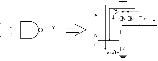
Figure 1: Three-input NAND gate
The connecting fault model: Crossing over faults are caused by shorts between signal
lines in the circuit. For example, a short between lines 1 and 2 of the NAND gate appeared in Figure 2.1 can be modeled in two ways: lines 1 and 2 are associated together utilizing net 1 or net 2 as an input. These faults can be identified by test (1, 0, 1) or (0, 1, 1) separately. Note that stuck-at faults can be modeled by shorts. For instance, 1-SA1 fault is proportionate to a short between the source and the gate of transistor P1, though 0-SA1 fault is equal to a short between the source and the gate of transistor N1.
The delay fault model: A delay or transition fault modifies the signal engendering delay
along the faulty line (P. K. Lala 2005, P. Agrawal, V. D. Agrawal, S. C. Seth, 2002)[3]. As a result, signals can touch base at the outputs of the circuit earlier or after the time anticipated. Testing delay faults in asynchronous circuits is hard because of the nonappearance of a synchronization clock.
3. TRANSISTOR-LEVEL FAULT MODELS
Past work concerning the precision of gate-level fault models has been reported. Exploratory results with test chips demonstrated that 20.8% of every faulty block had no gate-level stuck-at faults(A. Pancholy, J. Rajski, L. J. McNaughton, 2002)[4]. Different results have demonstrated that 36% of all faults are of the non-stuck-at assortment(J. Shen, W. Maly, F. Ferguson, 2006) [5]. As indicated by these results the use of tests which accommodate the discovery of all single gate-level stuck-at faults in the picked chips still "pass" faulty circuits. Fault models portrayed at the transistor level are more exact and, thus, offer a superior scope of fabrication faults in the circuit under test. Line stuck-at, stuck-open and crossing over fault models are utilized to portray the impacts of the larger part of fabrication faults in CMOS designs(H. H. Chen, R. G. Mathews 2004, J. A. Abraham, W. K. Fuchs, 2009, M. Abramovici, M. Breuer, A. D. Friedman,
2007)[6].The stuck-at fault model-As was specified over the stuck-at fault model assumes that a
Figure 2: Locations of line stuck-at faults and their interpretation in a fragment of CMOS design
The stuck-open fault: The stuck-open fault model speaks to a fault impact caused by a
fabrication disappointment which forever disengages the transistor stick from the circuit hub. Stuck-open faults can be opens on the gates, sources or depletes of transistors. Within the sight of a solitary stuck-open fault (SO) there is no path from the output of the circuit to either Vdd or Vss through the faulty transistor. For instance, within the sight of fault P1-SO output y can't be set high since there is no association between Testing Asynchronous Circuits - Related WorkThese voltage levels are very near the comparing logical 1 and 0 voltage levels since output y was beforehand set to the same logical values. Faults 1-SA1 or 3-SA0 result in a 'coasting zero' (0') or 'drifting one' (1') output signal separately. The output capacitance of the inverter can be considered as a dynamic memory element which keeps its precharge esteem for a specific time. It is assumed that the time between the uses of two test vectors is sufficiently little not to permit a coasting output voltage level to come to the CMOS edge level (R. L. Wadsack, 2006, M. K.
Reddy, S. M. Reddy, 2006)[7]. In the future we will treat feeble and drifting logical
values as typical ones.
The bridging fault model: It has been demonstrated that in CMOS technology a
connecting fault at the transistor level can change over a combinational circuit to a consecutive one.This makes additional issues for identifying such faults. Some connecting faults at the transistor level representation of the circuit under test have no logic acknowledge at the gate level. Testing for such faults requires the circuit structure to be tested which isn't simple.
4. TESTING DELAY-INSENSITIVE AND SPEED-INDEPENDENT CIRCUITS
The circuit responds with:
[Req]; Ack↑; [¬Req]; Ack↓, (2.2)
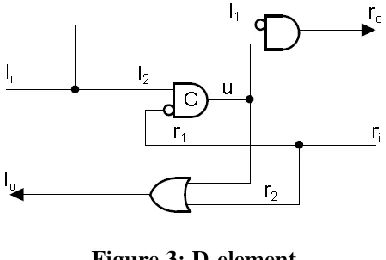
where a handshake development [exp] indicates the sitting tight for the Boolean articulation (exp) to end up noticeably evident(A. J. Martin,2009)[10].As a result, within the sight of a stuck-at fault on any of the control lines (Req or Ack) either the environment or the faulty circuit will hold up for eternity. It has been watched that speed-autonomous circuits are self-checking within the sight of output stuck-at faults(P. A. Beerel, T. H.-Y. Meng, 2002)[11] some stuck-at input faults in speed-autonomous circuits can cause untimely terminating. Untimely terminating is a transition which happens too soon as per the without fault circuit particular. The location of such faults requires an extraordinary testability analysis to be done. Figure 2.4 delineates an implementation of a D-element which groupings two four-stage handshakes.
Figure 3: D-element
Backward propagation: It was demonstrated to discover a standard D-algorithm can be
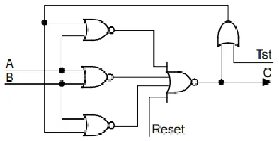
Figure 4: Gate level implementation of the modified C-element
5. TESTING BOUNDED DELAY CIRCUITS
Testing asynchronous sequential circuits
The most punctual asynchronous consecutive circuits were designed utilizing Huffman limited state machines(S. H. Unger, 2006)[12]. The combinational logic is bolstered by the essential inputs and the state inputs (SI) which are created by the criticism delay elements. After the utilization of each input vector to the PI inputs the state machine moves into another state changing its state outputs (SO) and creating another vector on its essential outputs. The Huffman model appeared in Figure 2.6a can be utilized to design bounded delay asynchronous circuits. Since we have to ensure that the combinational logic has settled because of another input before the present-state sections change, the decision of appropriate delay elements is important. An algorithm for producing tests to identify stuck-at faults in asynchronous consecutive circuits in light of the Huffman model has been reported(G. R. Putzolu, J. P. Roth, 2001)[13]. This algorithm depends on an expansion of the D-algorithm. It was assumed that a stuck-at fault F changes just the logical function of S. The fundamental test methodology proposed comprises of the accompanying advances:
1) Transform the discovery strategy of fault F in S into the identification of a comparing set of faults in an iterative combinational logic circuit got from S;
2) stretch out the D-algorithm to infer a test T for in ;
3) Recreate the test in S to check regardless of whether T is a test for F.
Testing micropipelines
There are a couple of works gave to fault modeling and fault testing issues in micropipelines(S.
Pagey, G. Venkatesh, S. Sherlekar, 2002, A. Khoche, E. Brunvand, 2004)[14]. Stuck-at faults
in the control part, combinational logic blocks and latches of the micropipeline have been considered.
setting the latches in the straightforward mode has no repetitive faults.
Single stuck-at faults: Any stuck-at fault on the inputs or outputs of the lock is proportional to the proper fault in the combinational logic. A stuck-at fault on the control lines of the hook keeps the generation of any occasions in the lock. This causes the micro pipeline to stop.
Single stuck-at-pass faults: These faults set a register bit of a lock in pass mode for all time. A stuck-at-0 fault on the empower input of the hook outlined in Figure 1.6 makes the faulty lock straightforward for all time. A two example test is required to recognize this kind of fault.
6. CONCLUSION
The most generally utilized fault models depicted fault practices of asynchronous circuits are stuck-at and delay (transition) faults. The stricter the confinements that are forced to the delays in the asynchronous circuits, the more intensive the testability analysis that is required. Testing asynchronous VLSI designs displays new issues which must be tended to before their business potential can be figured it out. The logic redundancy which is involved in the design of asynchronous circuits to guarantee their peril free conduct makes their testing troublesome or even unthinkable. Testing for perils and races in circuits without a synchronization clock isn't minor. The scan test procedure has been adjusted well to the testing of asynchronous circuits. Be that as it may, design for testability issues for asynchronous circuits have not been very much tended to on account of the challenges portrayed previously.
REFERENCES
1. J. A. Abraham, W. K. Fuchs 2009, G. Russell, I. L.2000 “Tutorial: VLSI Support Technologies-Computer-Aided Design, Testing and Packaging”, IEEE Computer Society, Los Alamitos, Calif., 1982, pp. 228-308.
2. E. J. McCluskey 2010, G. Russell, I. L.2000, and N. H. E. Weste, K. Eshraghian, 2003)[, “On random pattern testability of digital circuits”, Proc. 12th Int. Conf. on Diagnostic Support of Digital Systems, Praha, Czech Republic, Sept. 1989, pp. 217-218.
3. P. K. Lala 2005, P. Agrawal, V. D. Agrawal, S. C. Seth, 2002 “Linear test times for delay-insensitive circuits: a compilation strategy”, IFIP WG 10.5 Working Conference on Asynchronous Design Methodologies, Editors S. Furber, D. Edwards, Manchester, 1993, pp. 13-27.
5. J. Shen, W. Maly, F. Ferguson, 2006), “Information and communication theory”, Blackie & Son Ltd., 1966.
6. H. H. Chen, R. G. Mathews 2004, J. A. Abraham, W. K. Fuchs, 2009, M. Abramovici, M. Breuer, A. D. Friedman, 2007), “CAD for VLSI”, Van Nostrand Reinhold (International), 1985.
7. R. L. Wadsack, 2006, M. K. Reddy, S. M. Reddy, 2006, “Advanced simulation and test methodologies for VLSI design”, Van Nostrand Reinhold (International), 2000.
8. David, R. Ginosar, M. Yoeli, “Self-timed is self-diagnostic”, TR-UT- 84112, Department of Computer Science, University of Utah, Salt Lake City, UT, USA, 2000.
9. P. Hazewindus, 2005) “On the design of at-speed testable VLSI circuits”, Proc. 13th IEEE VLSI Test Symposium, Princeton, New Jersey, USA, May 1995, pp. 290-295. 10.A J. Martin, “From communicating processes to delay-insensitive circuits”, Tech. Report,
Department of Computer Science, California Institute of Technology, Caltech-CS-TR-89-1, 2009.
11.P. A. Beerel, T. H.-Y. Meng, 2002) “SIMIC: design verification tool”, User's Guide, Genashor Corporation, N.J., 1994.
12.S. H. Unger, 2006) “Design to test: a definitive guide for electronic design, manufacturing, and service”, Van Nostrand Reinhold, New York, USA, 1990.
13.G. R. Putzolu, J. P. Roth, 2001) “Asynchronous sequential switching circuits”, Wiley-Inter science, New York, NY, 2006.