IJEDR1604018
International Journal of Engineering Development and Research (www.ijedr.org)98
Study, Evolution, Design and Analysis of CFBC
Boiler for usage of Biomass as a Fuel
1
Pothan kumar reddy p 2 Raja sekhar 3 Nanda kumar T 1
M. Tech Student 2Assistant Professor 3AGM (CPP) 1
Department of Thermal and energy Engineering 1
The Global College of Engineering, kadapa, Andhra Pradesh, India
________________________________________________________________________________________________________
Abstract - In the work some parts of a laboratory scale CFBC are designed and developed with in department. Biomass rice husk were additionally ready and tested with in the circulating fluidized bed combustor system. A mathematical model was additionally developed to study the physico-chemical parameters of a 30 MW circulating FBC system at Bharathi cpp. Effect of the different parameters like particle size, bed temperature , ash content and moisture in fuel on the bubble diameter, minimum fluidization velocity and superficial velocity have been studied.
Index Terms - CFBC boiler ,Design , Analysis , CPP .
________________________________________________________________________________________________________
I.INTRODUCTION
The Bharathi cpp power plant has 1 unit having a generation capacity of 30MW. The electricity produced is supplied to private and government parties or 30 MW are used by the company itself and the rest is sold. The 30MW power plant consists of turbine backed by one 130 TPH CFBC boiler The study specifically directed at identifying the Effect of the different parameters like particle size, bed temperature , ash content and moisture in fuel on the bubble diameter, minimum fluidization velocity and superficial velocity have been studied. The operating temperature 540±5°C and the operating pressure is 109 Kg/ cm2.
II.DEVELOPMENT OF FLUIDIZED BED COMBUSTION (FBC) TECHNOLOGY:
With escalating prices of oil & gas during the last decade, the World power indus try shifted its focus from oil to coal, as coal is more abundant than oil or gas. Now-a-days Indian power industry is struggling with coal also, but to know how the FBC technology comes into the picture, it is necessary to go through the following consider ations. The pulverized fuel firing was developed earlier this century and universally used throughout the world for power generation but there are some limitations of the PF system. A pulverized fuel fired furnace designed for a particular type of coal cannot be used for any type of coal with same efficiency and safety. The size of the coal used is limited i.e. 70-100 micron therefore large investment is needed for coal preparing equipment & it’s Maintenance. The ignition of the coal particles becomes easy & combustion becomes steady when the temp in the furnace is 1650 deg centigrade. The amount of NOx formed is large compared to any type of combustion system as the temperature maintained in the furnace is high. The removal of SO2 demands high capital cost equipment. New rules & regulations imposed by government for the air pollution the cost of power generation went high as extra equipment are needed to control the air pollution to the required level. At present the boiler are designed to suit the fuel characteristics. The configuration and size of the boiler furnaces and the burner differ considerably depending upon whether the coal is anthracite, bituminous or lignite. Compared with the PF boilers the FBC Boilers can accept any fuel including low grade coals, oil, gas or municipal waste and can also control SOx and NOx emissions effectively.
III.PRINCIPAL OF FBC SYSTEM
IJEDR1604018
International Journal of Engineering Development and Research (www.ijedr.org)99
a saving of about 10% in operating cost & 15 % in capital cost could be achieved for unit rating 120mw.Size of the coal used is 6 to 13mm.IV. FUNDAMENTALS OF FLUIDIZATION
Fluidization is the operation by which the solid are transformed into fluid like state through air when air is passed vertically upward through a bed of solid particles supported by a grid.
1) Fixed bed:
The air at low velocity will tends to follow the path of least resistance & pass upward through the bed with pressure drop. This is called fixed bed
2) Minimum Fluidization:
With increase in velocity of air a point is reached when the solid particles just suspended in the upward flowing air. The bed is considered to be just fluidized and referred to as a bed at minimum fluidization. (The weight of the air in any section of bed is equal to weight of air & solid particles in that section).
3) Bubbling Bed:
Any excess air above the minimum fluidization will cause bubble formation and the excess air will escape the bed as bubble. This state is called as bubbling bed.
4) Turbulent Bed:
As the velocity of air through bubbling bed is increased the bed expands & the bubbles constantly collapse and reform the bed surface is highly diffused & particles are thrown off into freeboard above. Such a bed is called as turbulent bed. 5) Circulating Fluidized Bed:
With further increase in air velocity the bed particles are entrained, separated from air and returned to the base of furnace. This is called circulating bed.
6) Circulating Fluidized Bed:
With further increase in air velocity the bed particles are entrained, separated from air and returned to the base of furnace. This is called circulating bed.
V.LITERATURE REVIEW
History of FBC during the 70s and also in 80s, it appeared that conventional pulverized coal -fired power plants had reached a plateau in terms of thermal efficiency. The efficiency levels achieved were of the order of 40 percent in the US and also in UK. An alternative technology, Fluidized Bed Combustion (FBC), was developed to raise the efficiency levels. In this technology, high pressure air is blown through finely ground coal. The particles become entrained in the air and form a floating or fluidized bed. This bed behaves like a fluid in which the constituent particles move to and fr o and collide with one another.
The circulating fluidized bed (CFB) had a curious beginning. Warren Lewis and Edwin Gilliland conceived a new gas–solid process at the Massachusetts Institute of Technology in 1938 when they were trying to find an appropriate gas – solid contacting process for fluid catalytic cracking. The first CFB boiler, designed exclusive ly for the supply of steam and heat,
was built in the Vereingte Aluminum Werke at Luenen, Germany in 1982. This plant generated 84 MW total (9MW electricity, 31 MW process steam, 44 MW molten salt melt) by burning low-grade coal washery residues in the presence of limestone. Following a series of experiments in their Hans Ahlstrom Laboratory, they built the first commercial CFB boiler in Pihlava, Finland. It was a 15 MW (thermal output) boiler retrofit to an existing oil -fired boiler to replace expensive oil with peat. Initially the circulating fluidized bed boilers built by Ahlstrom were primarily for burning multifuel or low-grade fuels including bark, peat, and wood waste. Later boilers were designed exclusively for coal.
VI. DEVELOPMENT OF THE MODEL
6.1 Physico-Chemical Parameters of the Bharathi cpp Plant
An mathematical model have been developed to study physico-chemical parameters viz. bubble diameter , minimum fluidization velocity and superficial velocity of an circulating FBC system using Biomass at the Bharathi cpp.
6. 1.1 Superficial Velocity
Stoichiometric air feed rate is known from the fuel composition, f u e l feed rate from simple stoichiometric relationship as follows:
𝐹𝑀𝑇𝐻=𝑊𝑓𝑢𝑒𝑙(1.0-XW)
[12.0𝑋𝐶+𝑋𝐻4.0+32.0𝑋𝑆+32.0𝑋𝑂]
0.21 g. mol/s
Where Wfuel is fuel feed rate into combustor (g/s), XC, XH, XS, XO,
XW are ultimate moisture content, hydrogen, sulphur, oxygen and carbon of fuel respectively. Actual molar feed rate of the fluidizing air is calculated as:
FME =FMTH (1.0 + Exair ) g.mol/s
IJEDR1604018
International Journal of Engineering Development and Research (www.ijedr.org)100
ρ
3ρ
32
Exair : fractional excess air
Now superficial velocity is calculated by :
𝑈0= 𝐹𝑀𝐸𝑅𝑡𝐺𝑏
𝑃𝑎𝑣𝐴𝑡
Where,
R: Gas constant = 82.06 atm.cm3/(g.mol.K) Tb : Absolute bed temperature (K)
Pav: Average pressure in combustor (atm) At : Cross-sectional area of bed (cm2)
6.1.2 Minimum Fluidization Velocity
Several correlations are available in literature to define the minimum fluidization velocity, application of which varies to an great extent depending upon particle size in bed.
Geldart (1981) has b e e n pointed out that for the particle size〉 100 µm , Wen, Yu (1966) correlation gives best result. But, none of correlation is applicable if agglomeration, sintering is takes place in fluid bed. Wen , Yu (1966) correlation was used to calculate minimum fluidization velocity in present model as the particles are greater than the 100 µm.
𝑈𝑚𝑓=( 𝜇𝑔
𝐷𝑃𝜌𝑔) [{(33.7
2) +0.0408(𝑑𝑝𝑎𝑣) 3
𝜌𝑔(𝜌𝑝−𝜌𝑔)𝑔
𝜇𝑔2 }
0.5
− 33.7] 𝑐𝑚/𝑠
Where,
ρg = 353.2 ×10 Tb’
Where, 𝜌𝑝= 𝐾 + 𝐴 100
A : Ash content in the fuel (%)
Umf : Minimum fluidization velocity (cm/s) dp : Fuel particle diameter (cm)
µg : Viscosity of the fluidizing gas (g/cm.s) dpav : Average diameter ofthe fuel particles (cm)
g : Density of fluidizing gas (g/cm ) p : Density of fuel particles (g/cm ) K : Constant =1.25
Tb : Bed Temperature (K)
6.1.3 Viscosity of Fluidizing Gas
Viscosity of the fluidizing air is known from the Chapman-Ensco equation using values of the collision integral, Lennard-Jones parameters at prevailing bed temperature. These main parameters can be found in work of Bird al. (1960). Final viscosity expression, is the function of the bed temperature, is given below
µg = 1.4(101)(Tb ) 2 g/cm.s
6.1.4 AVERAGE EQUIVALENT BUBBLE DIAMETER
There are number of correlations were found in literature for estimation of the bubble diameter in an fluidized bed. The One of commonly used correlation be proposed by Mori and When (1975) taking into account effect of the bed diameter and distributor type on the bubble diameter as follows:
𝐷𝑏 = 𝐷𝑏𝑚− (𝐷𝑏𝑚− 𝐷𝑏𝑜)exp (−0.15/𝐷𝑅) Where,and (for the perforated distributor plates with number of orifice openings = ND)
Where,
Dbo= 0.376(U o− U mf ) for porous distributor plate (28)
IJEDR1604018
International Journal of Engineering Development and Research (www.ijedr.org)101
Dbm : Maximum bubble diameter (cm)ND : Number of orifice openings
Though, Mori and Wen (1975) correlation thus used for the laboratory type fluidized bed combustors have porous, perforated distributor plates, somewhere the bubble growth is limited by the walls of combustor, although Rowe (1976) has offered an expression to estimate the bubble diameter for the industrial scale combustors where such limitations are not expected due to the large cross-section of such combustors Which is given below
Where, Z : Bed height (cm)
We used Mori and Wen (1975) correlation for the estimation of bubble diameter at the Bharathi cpp plant is an industrial scale combustor.
Db = (U o−U mf).Z 0.75 .g −0.25 (29) VII. RESULTS AND DISCUSSION
The mathematical model is developed to predicts variation of the physico-chemical parameters like bubble diameter, minimum fluidization velocity and superficial velocity .
Effect of the different parameters like particle size, bed temperature , ash content and moisture in fuel on t h e bubble diameter, minimum fluidization velocity and superficial velocity have been studied.
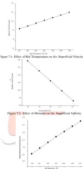
Figure 7.1 shows variation of the superficial velocity with the bed temperature. It’s been observed that as bed temperature increases the superficial velocity is also increases, s o t h e superficial velocity is directly proportional to the bed temperature. This happens due to fact that the bed temperature is increased resistance offered to fluid flow is then reduced. As effect less velocity is necessary to drag fluid particles.
Figure 7.2 shows variation of the superficial velocity with the moisture content in the fuel. It’s been observed that as percentage of the moisture content in fuel fed to combustion chamber increases superficial velocity will decreases. This happens due to fact that the moisture content in the fuel increases stoichiometric air feed rate will decreases due to that which actual molar feed rate of the fluidizing air decreases because the superficial velocity is directly proportional to the actual molar feed rate of fluidizing air. So, this results superficial velocity decreases by increasing the moisture content.
Figure 7.3 shows variation of the minimum fluidization velocity with the bed temperature. It’ s been observed that when the bed temperature is increased minimum fluidization velocity will increases. This happens due to fact that the bed temperature increases viscosity of the fluidizing gas increases. This is due to increase in viscosity of the fluidizing gas and resistance offered to the fluid flow increases this results in minimum fluidization velocity increases.
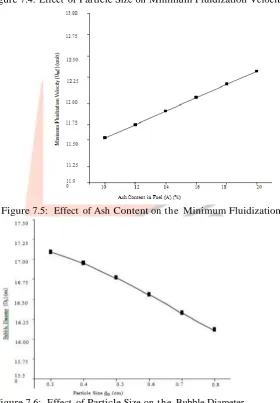
Figure 7.4 and 7.5 shows variation of the minimum fluidization velocity with the particle size, ash content in fuel respectively. It’s been observed that the particle size, ash content increases t he minimum fluidization velocity increases. As the density and size increases, this gives more resistance to fluidizing gas and then causes more pressure drop.
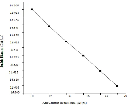
Figure 7.6 and 7.7 shows variation of the bubble diameter with t h e particle size, ash content in fuel respectively. It’s been observed that the particles size, ash content in the fuel increases t he bubble diameter decreases.
This happens due to fact that the increase in particle size, ash content in t h e fuel there is an increase in the minimum fluidization velocity which reduces the bubble diameter. This has been established in work of the Stubington et al. (1984). They measured bubble sizes in the fluidized bed of elutriated carbon at temperatures ranging from the ambient u p to 1000°C, using the 3 dimensional resistivity probe and stainless steel tuyere cap distributor plate which is similar to one used in Bharathi cpp plant. They have report that with the excess fluidizing gas velocity, the bubble diameter reduces by 5 to 15 % with increase in the particle size.
Importance of the Bubble Stirred Bed of Particles • Bubbles may cause oxygen by-passing.
• Bubbles stir in the bed and thus enhance heat transfer to immersed tubes; control of bubble size may thus be very important.
• Bubbles promote particle mixing. The relative magnitude of particle mixing times and carbon burnout times may decide the spacing of fuel feed points.
• The mechanism of bubble formation is important in distributor design.
• Knowledge of bubble mechanics gives a fair idea whether combustion is controlled by chemical rate or by diffusion.
IJEDR1604018
International Journal of Engineering Development and Research (www.ijedr.org)102
Figure 7.1: Effect of Bed Temperature on t he Superficial VelocityFigure 7.2: Effect of Moisture on t he Superficial Velocity
IJEDR1604018
International Journal of Engineering Development and Research (www.ijedr.org)103
Figure 7.4: Effect of Particle Size on Minimum Fluidization VelocityFigure 7.5: Effect of Ash Content on t he Minimum Fluidization Velocity
IJEDR1604018
International Journal of Engineering Development and Research (www.ijedr.org)104
Figure 7.7: Effect of Ash Content on t he Bubble DiameterVIII. CONCLUSION
Superficial velocity will increase with increase in t h e bed temperature and then decreases with the increase in the moisture content in fuel. Minimum fluidization velocity increases with the increase in bed temperature and particle size, the ash content in fuel. Bubble diameter decreases with the increase in particle size, ash content in the fuel.
REFERENCES
[1] Operation and maintenance manuals of Bharathi cpp
[2] Xiaozhong, LU Junfu, YANG Hairui, LIU Qing, YUE Guangxi, FENG Junkai, Comprehensive Mathematical Model For Coal Combustion In The Circulating Fluidized Bed Combustor by “Published in Tsinghua Science and Technology, 2001, 6(4): 319~325”.
[3] Ravindra Kumar and K.M.Pandey, Cfd Analysis Of Circulating Fluidized Bed Combustion by “IRACST – Engineering Science and Technology: An International Journal (ESTIJ), ISSN: 2250-3498, Vol.2, No.1, 2012” [4] Thenmozhi Ganesan, Dr.Sivakumar Lingappan, A Survey on Circulating Fluidized Bed Combustion Boilers by
“International Journal of Advanced Research in Electrical, Electronics and Instrumentation Engineering (An ISO 3297: 2007 Certified Organization) Vol. 2, Issue 8, August 2013”.
[5] Khurram S, Mahmood S, Waqar A. Khan, Najaf A, Niaz A. Akhtar, Parametric Study of NOx Emissions in Circulating Fluidized Bed Combustor by “Journal of Pakistan Institute of Chemical Engineers JPIChE 40 (1) 2012: : 61-68 journal homepage: www.piche.org.pk/journal Submitted: 06/08/2012, Accepted: 25/09/2012, Online: 22/10/2012”.
[6] K.M.Pandey and Ravindra Kumar, Numerical Analysis of Coal Combustion in
Circulating Fluidized Bed by “International Journal of Chemical Engineering and Applications, Vol. 2, No. 6, December 2011”.
[7] XIE Jian-jun, YANG Xue-min, ZHANG Lei1, DING Tong-li1, SONG Wen-li, LIN Wei-gang, Emissions of SO2, NO and N2O in a circulating fluidized bed combustor during co-firing coal and biomass by “Journal of Environmental Sciences 19(2007) 109– 116 ISSN 1001-0742, Received 16 January 2006; revised 26 January 2006; accepted 29 March 2006”.
[8] Mohit Gaba, Mathematical Modeling of Bubbling Fluidized Bed Combustor of Power Plant Based on Biomass Fuel by “International Journal of Applied Engineering Research. ISSN 0973-4562, Volume 8, Number 18 (2013) pp. 2121-2126 © Research India Publications http://www.ripublication.com/ijaer.htm”.
[9] Ion V. ION, Florin POPESCU, Dynamic Model Of A Steam Boiler Furnace By “The Annals Of Dunarea De Jos University Of Galati Fascicle V, Technologies In Machine Building, ISSN 1221- 4566, 2012”.