University of South Carolina
Scholar Commons
Theses and Dissertations
2017
Enhanced Dropwise Condensation Via Wettability
Contrast Mechanism
Mohammad Alwazzan
University of South Carolina
Follow this and additional works at:https://scholarcommons.sc.edu/etd
Part of theMechanical Engineering Commons
This Open Access Dissertation is brought to you by Scholar Commons. It has been accepted for inclusion in Theses and Dissertations by an authorized administrator of Scholar Commons. For more information, please [email protected].
Recommended Citation
Alwazzan, M.(2017).Enhanced Dropwise Condensation Via Wettability Contrast Mechanism.(Doctoral dissertation). Retrieved from
ENHANCED DROPWISE CONDENSATION VIA WETTABILITY CONTRAST MECHANISM
by
Mohammad Alwazzan
Bachelor of Science
University of South Carolina, 2011
Master of Engineering University of South Carolina, 2012
Submitted in Partial Fulfillment of the Requirements
For the Degree of Doctor of Philosophy in
Mechanical Engineering
College of Engineering and Computing
University of South Carolina
2017
Accepted by:
Chen Li, Major Professor
Jamil Khan, Committee Member
Kevin Huang, Committee Member
Xinyu Huang, Committee Member
Roger Dougal, Committee Member
DEDICATION
ACKNOWLEDGEMENTS
At 2013 with a bachelor and master degree both majored in mechanical
engineering received from University of South Carolina in 2011 and 2013, respectively, I
fortunately joined Dr. Chen Li’s group to work in his laboratory, Micro/Nanoscale
Transport Lab. Since then, condensation was the phase change topic of my interest. With
a little knowledge to begin with and the tremendous support provided by Dr. Chen Li,
who not only professionally supervise my academic journey, but made it very pleasurable
experience, many challenges were overcome. Therefore I would like to present my
especial thanks to his kind and rich in knowledge personality. I would like also to present
my especial thanks for the Mechanical Engineering Department’s chair, Dr. Jamil Khan,
who always provide an endless support for the department, and have always inspired me
by his great mind and humble personality. I would like also to include his administrative
assistances, Misty O'Donnell, and Lalitha Ravi.
I would like to thank especially my prestigious committee members, the chair
department of electric engineering Dr. Roger Dougal, Dr. Xinyu Huang, and Dr. Kevin
Huang who always provided a great assistance. I would like also to thank the machine
shop expert, Mr. Bill Bradley, who always helped me in parts fabrication.
My thanks should also presented to my former co-workers and friends, Dr.
Xiaming Die, Dr. Fanghao Yang, Dr. Xiaopeng Qu, Dr. Mehdi Famouri, and Dr. Karim
Egab. In addition, I would like to thank my current co-workers and postdoctoral scholars,
the currant graduate co-workers, Wenming Li, Wei Chang, Ahmad Abdulshaheed,
Raikan Dawas, GuanHan Huang, Mostafa Mobli, Congcong Ren, Jiaxuan Ma, and
Yueyang Zhao, whom I enjoyed working and exchanged valuable knowledge with, and
considered to me as an academic family.
I would also like to express my great thanks for my mother who always
unconditionally supported me with her worm loving care along all these academic years.
In addition, I would like to especially mention my most motivation and inspiration in life,
my two daughters, Joori Alwazzan and Yasmeen Alwazzan.
Finally, I would like to acknowledge funding received by the National Science
Founding (NSF) under award 1357920, and the office Naval Research (ONR) under grant
N000140810080 for supporting this work in part. I also would like to emphasis my
thanks for Benoit Semin who developed the original MATLAB program, Dr. Xiaopeng
Qu who helps in maintaining the permission and Mr. Ahmed Shehab Khan for his effort
ABSTRACT
Condensation heat transfer performance can be improved by many methods
including the most common used method, which is by increasing the droplet removal rate
of the condensing surface. Commonly, this approached can be achieved by promoting a
dropwise condensation mode in which super/hydrophobic coatings can be applied on the
entire condenser surface to reduce the surface wettability degree. In this dissertation, two
main approaches were adapted to enhance the condensation heat transfer performance of
the condensing surface via wettability contrast mechanism. Three approaches of
investigation were performed to better understand such dropwise condensation promoter
methods.
In the first part, alternative mini-scale straight patterns consisted of hydrophobic
(β) and less-hydrophobic (α) regions were formed on surfaces of condenser copper tubes.
The existence of the two adjacent regions carrying different surface energy generates
wettability gradient which can mitigate condensate and increase its removal rates. A
parametric study was conducted to experimentally determine the influence of (β/α) ratio
on the condensation heat transfer performance and the droplet dynamic under saturation
condition near the atmosphere pressure with the presence of non-condensable gases (air).
The results reveal that all patterned surfaces exhibited a drastic enhancement in terms of
condensation heat transfer coefficient and heat flux compared to those of filmwise
condensation. More interestingly, some (β/α) ratios significantly outperformed a surface
exists with β and α-regions widths of 0.6 mm and 0.3 mm, respectively. The heat transfer
coefficient of the sample with the optimum ratio peaked at a value of 85 kW/m2 K at
subcooling temperature of 9°C, which was about 4.8 and 1.8 times that of a complete
filmwise and dropwise condensation, respectively. This term of investigation also
demonstrated that the β-regions served mainly as droplet nucleation sites with rapid
droplets mobility; whereas the α-regions promoted droplet removal from the neighboring
β-regions, and served as drainage paths, where condensate can be drained quickly under
gravitational force. Furthermore, the existence of both α and β-regions on the condensing
surface controls the droplets maximum diameters of the growing droplets on the
β-regions. The maximum diameter is approximately 0.56 ± 3 % mm, which is 26 % the size
of the droplets maximum diameter on a full β-region surface.
In the second part of the study, the main objective was to analyze the droplet
dynamics during condensation on hybrid-wettability patterned surfaces of horizontal
oriented tubes, and to investigate why some patterned surfaces with alternative parallel
straight stripes consist of hydrophobic (β) and less-hydrophobic (α) regions at different
ratios exhibited higher heat transfer rate than others. Three major outlines were found in
this course of the droplets dynamic investigation. First, the existence of an optimum (β/α)
ratio that maximized the condensation heat transfer rate was justified due to exhibiting
the maximum droplet departure frequency and the minimum droplet area coverage rate
relative to other tested samples. Second, the reduction in the heat transfer rate resulting
from any deviation from the optimum ratio was also identified. We observed that by
increasing the α-regions width, the condensation was dominated by a filmwise
of α-regions less than the optimum ratio was found to be unfavorable due to the increase
in the bridging droplets observed and discussed herein. Lastly, the undesirable observed
bridging phenomenon found to occur on all tested hybrid patterned surfaces, can
significantly influence the condensation heat transfer performance. A bridging droplet
can be referred to a droplet that joined or bridged by two, three, or four neighboring
α-stripes. Increasing these unwanted droplets formation frequency can induce additional
thermal resistance which can reduce the condensation rate. The most dominant and
frequent bridging droplet type observed herein was found to be for droplets that were
bridged by two α-regions, followed by those between three and four α-regions. A
quantitative method (i.e. Bridging coverage area rate) was adapted herein to quantify the
influence of the velocity, frequency, and size of the three types of bridging droplets on
the condensation rate of the hybrid patterned surfaces.
In the third part of the investigation, the same hybrid wettability concept was
applied however at a nanoscale instead. A bi-philic surface consist of nanoscale hybrid
wettability regions was developed by depositing different numbers of hydrophilic nickel
oxide layers on smooth nickel tubes surfaces via atomic layer deposition method (ALD).
The deposition nature of the ALD method allows for a certain amount of carbon, which is
hydrophobic in nature, in combination with the NiO to be deposited on the surface. The
existence of the contrast in wettability degree of the condensing surface helped in droplet
mitigation and improved the droplet removal rate. Moreover, the choice of nickel as a
material for such investigation can be justified by its relative stability among other
common condenser metals and their oxide. Most of the metal surfaces will be oxidized
saturation conditions of water vapor during condensation process. The deposition of NiO
layers on the Ni surface is basically mimicking the oxide layer that would be formed on
nickel surfaces during real applications. The condensation heat transfer performances for
all samples with different NiO layers, i.e. 50, 100, 200, and 400 cycles of ALD. A
significant enhancement was achieved especially for the sample with least deposition
number of NiO ALD cycles. The maximum condensation heat transfer coefficient
achieved was at subcooling temperature of about 3.5°C with a value of 100 kW/m^2 K,
which is 4.2 times the FWC. While, the heat flux max out at subcooling temperature of
about 11.0°C with value of about 700 kW/m^2 which is 3.9 times the FWC. The
coexistence of the hydrophobic carbon and hydrophilic NiO at atomic concentration ratio
of about 3 to 1 (i.e. 74.3 % to 25.7 % for carbon to NiO, respectively) allows for a proper
droplets mitigation due to the existence of bi-philic condensation mode which was driven
by the capillary force.
In summary, this capillary-driven mechanism allows droplets to be expediently
removed from the condensing surface at higher rates, allowing more surface area to be
exposed to the surrounding vapor and leading to a substantial enhancement in the
condensation heat transfer coefficient. Such mechanism can be achieved by introducing
two or more regions with different wettability degrees on the condensing surface
following a pattern. The patterns can be studied and designed in such away it can deliver
PREFACE
Many methods were developed to enhance the condensation heat transfer
performance by reducing the surface wettability to achieve a dropwise condensation. The
literature review in Chapter 1 includes mainly three categories. The first category will
discuss methods, which were used to reduce the surface free energy to achieve dropwise
condensation. In the second category, the discussion will include condensing surfaces
exhibiting hybrid wettability at nano/microscale aiming mainly to increase the droplet
nucleation and removal rates [47-50, 52-57, 75-77]. The third category will discuss
surfaces that exhibited wettability gradient at the mini-scale, which is the same approach
adapted in Chapter 2, aiming to promote droplets mitigation via the capillary driven force
[59-64, 81, 82].
Followed the literature review is Chapter 2, which proposing a method to enhance
the overall dropwise condensation via a capillary-driven force, which mitigates the
condensate. This mitigation of condensing droplets is achieved by forming straight
patterns on copper tubes. These patterns exhibit both hydrophobic and hydrophilic strips
at a mini scale, the former mainly acted as nucleation sites for condensate, whereas the
latter acted mainly as condensate drainage paths. The experimental investigations in this
section have two main parts. The first part will focus on the condensation enhancement,
which will be categorized by the condensation heat transfer performance. Whereas, the
second part of Chapter 2 will focus on analyzing the droplet dynamic and behavior during
wettability patterns can increase the droplet departure frequency for certain hydrophobic
to hydrophilic ratios. However, the study will also show that some other ratios cannot
gain a significant enhancement due to a bridging phenomenon found existing during
condensation on such hybrid surfaces. The phenomenon and its influence on the
reduction in condensation heat transfer performance will be discussed.
Chapter 3 will discuss the nanoscale wettability contrast, which was achieved by
depositing nickel oxide layers on nickel surfaces via atomic layer deposition method to
mimic the oxidation layer that would be formed in industrial application. The determined
heat transfer measurement and visualization recording will be used to investigate the
influence of combining two wettability degrees at nanoscale. The contrast in the
wettability was identified by the surface chemical components, which consisted of
hydrophilic nickel oxide and hydrophobic carbon. The ratio between nickel oxide and
TABLE OF CONTENTS
DEDICATION ... iii
ACKNOWLEDGEMENTS ... iv
ABSTRACT ... vi
PREFACE ... x
LIST OF TABLES ... xiii
LIST OF FIGURES ... xiv
LIST OF SYMBOLS... xix
LIST OF SUBSCRIBES ... xxi
LIST OF ABBREVIATIONS ... xxii
CHAPTER 1: AN INTRODUCTION OF DROPWISE CONDENSATION PROMOTORS ... 1
CHAPTER 2: CONDENSATION ON MINISCALE HYBRID-WETTABILITY SURFACES ... 37
PART I: CONDENSATION HEAT TRANSFER CHARACTERIZATION ... 58
PART II: DROPLET DYNAMIC ANALYSIS ... 69
CHAPTER 3: CONDENSATION ON NANOSCALE HYBRID-WETTABILITY SURFACES ... 88
OVERALL CONCLUSION ... 104
FUTURE WORK ... 105
REFERENCES... 106
LIST OF TABLES
Table 2.1 Samples specifications and labeling. ... 40
Table 2.2 Instruments uncertainties ... 58
Table 2.3 Samples categorization ... 69
LIST OF FIGURES
Figure 2.1 Concept of droplet migration mechanism between two different wettability regions. (a) A condensing droplet grows on the β-region until its boundary touches with the neighboring α-regions. (b) The capillary-driven phenomena due to the existence of the two wettability neighboring regions, drags the droplet(s) from the lower wettability region to higher one, that is from β to α region, respectively. (c) Complete droplet removal and drainage occur within the higher wettability degree region under gravitational force ... 39
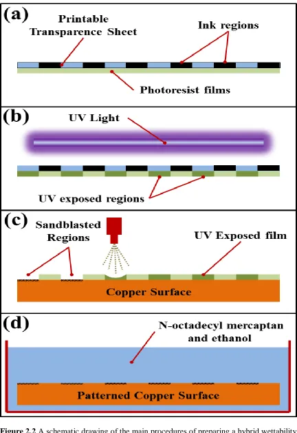
Figure 2.2 A schematic drawing of the main procedures of preparing a hybrid wettability pattern on the condensing surface of this study. (a) Fixing the printed transparent sheet which carries the designed pattern on top of the photoresist sheet. (b) Exposing both sheets to a UV light source that is facing the transparence sheet side. Only the regions of the photoresist film that is exposed to the light will be brittle which will be identical to the printed design of the transparent sheet. (c) Carefully fixing the photoresist sheet with the assist of the adhesive layer on top of the condensing surface. Applying a micro-abrasive blasting process on the photoresist side; the fine stream can only target the condensing surface areas beneath the brittle regions of the photoresist sheet. This allows the creation of roughened regions matching the pattern design of the photoresist sheet (d) Removing the photoresist sheet residual from the condensing surface followed by cleaning procedure, then immersing the condensing surface that carried the roughened pattern in the SAM solution for an hour ... 42
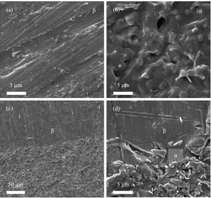
Figure 2.3 Scanning electronic microscopy images of the self-assembled monolayer coating on (a) β-region, (b) α-region, and (c, d) the interface between β and α-region of the patterned surface ... 44
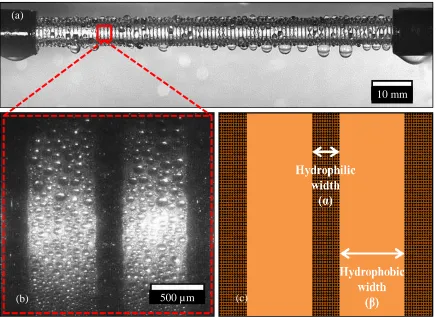
Figure 2.4 Condensation image of deionized water vapor on patterned copper tube, R2, in the experimental chamber under saturation condition of the atmosphere at subcooling temperature of 9°C is shown in (a). The β and α-regions are displayed in the enlarged image of a small section of the condenser surface area of (b), and illustrated by the schematic drawing in (c). ... 45
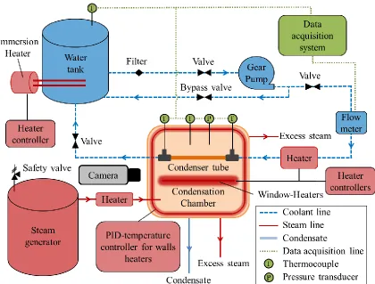
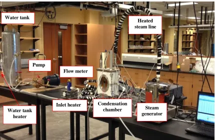
Figure 2.5 A schematic drawing of the experimental setup. The blue dashed lines represent the coolant system. A close loop system was adapted to circulating the coolant from a heated water tank to the test section at a constant flow rate. The red solid lines show the path of the deionized water vapor. The condensate drainage is represented by a double blue line. All the measurement instruments are connected to the data acquisition system as shown by the doted green lines. ... 47
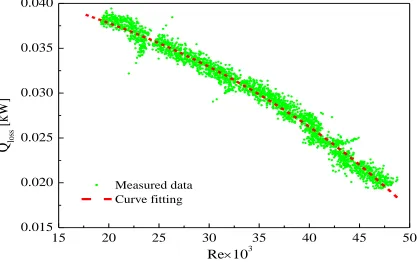
Figure 2.7 An example of the measured HT rate based on the coolant side as a function of Reynold number inside the insulated tube during a calibration experiment showing on the graph with green dot symbols. A curve fitting line presented by the dashed red line was used to consider the heat dissipated by any parts of the assembly but not the condensing tube, and used in Eq. (1) as Qloss. ... 53
Figure 2.8 Image of a smooth copper tube treated with H2O2 (Filmwise) undergoing filmwise condensation of water vapor under saturation condition near the atmosphere pressure ... 54
Figure 2.9 Experimental results of condensation (a) heat flux and (b) HTC as a function of surface subcooling temperature for “Filmwise” undergoing filmwise condensation of water vapor under saturation condition near the atmospheric pressure. The before refining two data sets in the graphs were determined by a direct surface measurement method (red solid dots), see section 2.7, and by the computing method illustrated in the data reduction section 2.5 (green hollow square), and compared with Nusselt model of filmwise condensation. ... 55
Figure 2.10 The results of condensation (a) heat flux and (b) HTC as a function of surface subcooling degree for the same data sets presented in Figure 9 after the refining process and adding the error bars. ... 56
Figure 2.11 Percentage of NCG as a function of (a) surface subcooling degree, and (b) the measured saturated pressure inside the testing chamber for all tested samples ... 57
Figure 2.12 Experimental condensation HT performance as a function of subcooling
(∆T = Tsat− Tw) for sample surfaces R2, R1.5, R1.2, F-β, F-α, and Filmwise undergoing water vapor condensation under saturation conditions near the atmospheric pressure (0.106 - 0.112 ± 0.002 MPa), and compared with Nusselt model of filmwise condensation. Both the condensation heat flux and HTC as functions of subcooling temperature for same samples sets are showing in (a) and (b), respectively. The error bars of all data computed by the method detailed in section 2.10 ... 60
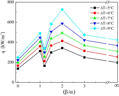
Figure 2.13 Condensation Heat flux as a function of the (β/α) ratio for sample R3, R2, R1.5, R1.2, R1, F-β, and F-α at 5, 6, 7, 8, and 9°C of surface subcooling under saturation pressure of (0.106 - 0.112 ± 0.002 MPa). The zero and infinity values presenting in the x-axis refers to sample Sandblasting and F-β, respectively ... 62
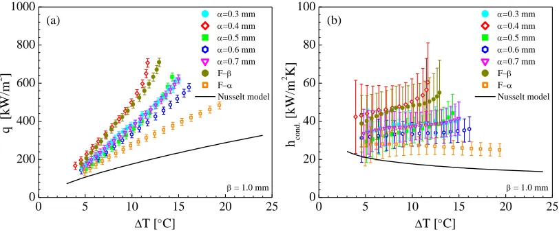
Figure 2.14 Condensation (a) heat flux and (b) HTC as a function of subcooling temperature for hybrid patterned samples with fixed β-regions width of 1.0mm and varied α-regions width (from 0.3 to 0.7), compared with F-β, F-α, and Nusselt model of FWC undergoing water vapor condensation under saturation conditions near the atmospheric pressure (0.106 - 0.112 ± 0.002 MPa). ... 63
0.002 MPa. The Red lines highlight a droplet undergoing direct migration from β to α-region, whereas green lines highlight a larger droplet undergoing first a direct migration from β to α-region, followed by bouncing and coalescing actions with neighboring droplet(s) as highlighted by the blue lines.) ... 65
Figure 2.16 Bridging phenomena under formation action. Time lapse snapshots via the recorded visualization during vapor condensation on R1.2 surface at a subcooling degree of 13.5°C, and saturated pressure of (0.106 - 0.112 ± 0.002 MPa)... 66
Figure 2.17 Mechanism of droplet under migration action from β to α-region due to the coalescence of small droplets near the α-boundaries which prohibits a growing droplet to reach a diameter equivalent to the width of β-region is illustrated by the (a) schematic and (b) time lapse images for a patterned sample with (β/α) ratio of (0.7/0.3) at subcooling temperature of 16.2°C, and saturated pressure of (0.106 - 0.112 ± 0.002 MPa). ... 67
Figure 2.18 Calibration to the size of falling droplets detected by (a) the original image and (b) the modified image. [Note: Sample R2 is showing in (a) and (b)]. A histogram of a case study of the percentage increase in the size of randomly selected droplets is presented in (c) which shows that the increase in the droplets size after the image modification was 30±5% of the original. The rectangular with the dashed black lines in (a) present the studied area of the global frame work ... 72
Figure 2.19 Heat transfer performance for R2, R1.2, F-β, and F-α undergoing water vapor condensation under saturation condition near the atmospheric pressure. The heat flux as a function of the subcooling temperature computed by the Droplet Analysis (DA) and Experimental (Exp.) methods are represented by the symbols and the dashed lines, respectively. The dashed lines present the curve fitting for the experimental results of part I of the same samples. The error bars determined by the error propagation associated with the computed area of the droplets. ... 74
Figure 2.20 Comparison of droplet size for sample R2, R1.2, F-β, and F-α is presented in the graph of (a) the average droplet departure diameter (computed by the DA method) as a function of the subcooling temperature. (b) Photographs of the condensing tubes undergoing condensation under saturation condition near the atmosphere and at coolant inlet temperature of 40±0.5 ⁰C. Random droplets circled by the same size rings for visual comparisons. ... 76
Figure 2.21 The average droplet departure frequency as a function of subcooling temperature for sample R2, R1.2, F-β, and F-α computed by the DA method under the global frame work. ... 77
(showing in the first image of column (a)) of the global frame work, the droplet departure frequency can be computed. ... 78
Figure 2.23 Droplets departure frequency as a function of the location along the x-direction of the tube R2 (showing in the top of the figure), R1.2, F-β, and F-α, computed by the DA method under the global frame work. The results were computed under the same condensation conditions, and coolant inlet temperature. The x-direction length of the tubes was divided into nine 10 mm-long sections. Note that the flow direction of the coolant inside the tube was from left to right. ... 80
Figure 2.24 Bridging droplet phenomenon during condensation on hybrid patterned condensers. (a) A schematic illustrating the three types of bridging droplets that were considered herein. (b) A photograph showing three types of the bridging droplets circled by red dashed lines forming on surface R2 that was undergoing water vapor condensation under saturated conditions of the atmosphere, and a coolant inlet temperature of 40±0.5 ⁰C. ... 81
Figure 2.25 histograms of the bridging droplets base diameter for bridging droplet occurred between (a) 2 α-stripes, (b) 3 α-stripes, and (c) 4 α-stripes, for sample R1.2 (row 1), R1.5 (row 2), and R2 (row 3). The analyzed bridging droplets population of the three samples was taken under the same condensation test conditions and coolant inlet temperature of 40±0.5 ⁰C. ... 82
Figure 2.26 The comparisons of the three bridging droplet variables for the three types of bridging droplets as a function of (β/α) ratio, are showing in (a) for the bridging droplet frequency, (b) for the bridging droplets base diameter, and (c) for the bridging droplets traveling/sliding velocity. [Note that all the results were computed under the same condensation test conditions and the same coolant inlet temperature]. ... 84
Figure 2.27 Bridging droplet coverage area rate as a function of (β/α) ratio for the three types of bridging droplet. ... 85
Figure 3.1 Surface characteristic presented by considering the surface wettability in (a) Contact angle measurement for the advance, receding, hysteresis, and static using water as the working fluid. Images showing in the top of the figures are for the static contact angles. ... 91
Figure 3.2 Atomic force microscopy results showing the surface roughness presented by Average roughness (Ra) [i.e. the average of the individual heights (asperities) and depths from the arithmetic mean elevation of the profile], and the root mean square roughness (Rq) [i.e. the square root of the sum of the squares of the individual heights and depths from the mean line]. ... 92
Figure 3.3 XPS result of the surface chemical components of sample Ni-NiO-ALD-50 prior to the condensation experiment. The figures from left to right present the peck intensity in arbitrary unit amount as a function of the binding energy for carbon, oxygen, and nickel oxide, respectively. ... 93
Figure 3.5 XPS results show the mass concentration percentage of carbon, oxygen, and nickel as a function of number of ALD-NiO cycles. ... 94
Figure 3.6 Experimental condensation heat transfer performance as a function of subcooling (∆𝑇 = 𝑇𝑠𝑎𝑡− 𝑇𝑤) for sample surfaces coated with different number cycles of
NiO ALD, 50, 100, 200, and 400 cycles undergoing water vapor condensation under saturation conditions near the atmospheric pressure, and compared with Nusselt model of filmwise condensation. Both the condensation heat flux and HTC as functions of subcooling temperature for same samples sets are showing in (a) and (b), respectively.. 96
Figure 3.7 Condensation heat transfer coefficient as a function of different number cycles of NiO ALD for all tested surfaces at four subcooling degrees, ∆T = 5, 6, 8, and 10 ℃. Images in the figures represent the same surfaces undergoing water vapor condensation under saturation conditions near the atmospheric pressure at subcooling of about 5℃. ... 97
Figure 3.8 Average maximum droplet base diameter of random droplets population during condensation on the surface of sample 50cyc - NiO ALD at different subcooling temperatures. ... 98
Figure 3.9 Photographs of condensation on the surfaces of the NiO ALD coated at inlet temperature of 35°C under saturation condition of the atmospheric pressure. Scale is 10 mm. ... 99
Figure 3.10 Image of distilled water droplets placed on the surfaces of the testing samples after etching with plasma cleaning system for all samples coated by NiO ALD. The figure show very low contact angles near to zero since the carbon contents etched away.. ... 100
Figure 3.11 Droplet dynamic on NiO ALD 50 cycles sample showing a random droplets movement in all direction including against the gravitational force. ... 101
LIST OF SYMBOLS
𝐴 surface area of the tube (m2)
𝐶 constant of Eq. (5)
𝑐𝑃 specific heat capacity (J/kg K)
𝐷 diameter (m)
ℱ droplet departure frequency (1/s)
𝑔 gravitational acceleration (m/s2)
ℎ heat transfer coefficient (W/m2 K)
ℎ𝑓𝑔 latent heat of evaporation (J/kg)
𝑘 thermal conductivity (W/m K)
𝐿 tube length (m)
𝑚̇ mass flow rate (kg/s)
𝑁𝑢 Nusselt number
𝑃 pressure (Pa)
𝑃𝑟 Prandtl number
𝑄 heat transfer rate (W)
𝑞" condensation heat flux (W/m2
)
𝑅 resistance (K/W)
𝑅𝑒 Reynold number
𝑈̅ overall heat transfer coefficient (W/m2 K)
𝑉̅ average volume of departure droplets (m3)
∆ difference (–)
𝜌 density (kg/m3)
LIST OF SUBSCRIBES
𝑐 ...coolant
𝑐. 𝑐𝑜𝑛𝑣 ... coolant convection inside the tube
𝑐𝑜𝑛𝑑 ...condensation
𝐶𝑢 ... copper
𝑐. 𝑤 ... coolant at wall temperature
𝑓 ... film
𝑖 ... inner
𝑖. 𝑐𝑠 ... inner cross section of the tube
𝑖𝑛. 𝑐 ... inlet of the coolant
𝑙 ... liquid
𝐿𝑀𝑇𝐷 ... log mean temperature difference
𝑜... outer
𝑜𝑢𝑡. 𝑐... outlet of the coolant
𝑠𝑎𝑡 ... saturation temperature
𝑡𝑜𝑡... total
𝑣 ... vapor
LIST OF ABBREVIATIONS
𝛼 ...less-hydrophobic region(s)
𝐴𝐹𝑀... atomic force microscope
𝐴𝐿𝐷 ... atomic layer deposition
𝛽 ...hydrophobic region(s)
𝐷𝑊𝐶 ... dropwise condensation
𝐹𝑊𝐶 ... filmwise condensation
𝐻𝑇... heat transfer
𝐻𝑇𝐶 ... heat transfer coefficient
𝑁𝑖... nickel
𝑁𝑖𝑂 ... nickel oxide
𝑅 ... ratio
CHAPTER 1:
AN INTRODUCTION OF DROPWISE CONDENSATION PROMOTORS
Condensation is an essential and yet widespread process that can be found in
many small-scale and industrial applications such as in power plants, water desalination
and harvesting, HVAC (Heating, Ventilation, and Air Conditioning), and
dehumidification [1-4]. Increasing the condensation performance efficiency can
significantly reduce the energy and materials consumption as well as capital and
operational costs. Condensation heat transfer (HT) performance can be enhanced using
diverse methods which are presented throughout numerous research studies. One of the
most common methods is by promoting dropwise condensation (DWC) mode since first
recognized by Schmidt et al. showing that the heat transfer coefficient of DWC can be
five to seven times that of the filmwise condensation owing to its superior heat transfer
rate to that of filmwise condensation (FWC) mode [5-9]. In general, an effective DWC
can be achieved when nonwetting superhydrophobic or incomplete wettable surfaces are
used as the condensing surface. These surfaces usually have higher drop nucleation site
densities, coalescence and droplet roll-off rates, resulting in a higher replenishment
frequency at smaller droplet diameters [10-14].
Many methods are developed to enhance the condensation heat transfer
performance by promoting DWC. Such promotors can be found in an experimental study
tested. The first sample was for a bare titanium surface without any modification
resulting in a contact angle of 86.06°. The second sample was chemically etched with
hydrofluoric solution to reduce the surface energy resulting in a contact angle of 60.87°,
resulting in a hydrophilic surface exhibiting a filmwise condensation. For the third
sample, the surface was chemically etched and treated with hydrogen peroxide solution
resulting in a hydrophobic surface with a contact angle of 100.41°. The condensation heat
transfer performances of all samples were measured using saturated water vapor under
the atmospheric pressure. The results show that a mixed condensation modes consist of
dropwise and rivulet filmwise condensation was achieved by the first sample, whereas,
the second sample exhibited a complete filmwise condensation. The third sample with a
high surface contact angle displayed a complete DWC. In addition, the effect of the
subcooling temperature (surface to vapor temperature difference) on the condensation
rate was also investigated. The results show the subcooling degree has a minor influence
on the condensation rate for the second and third samples, which determined by the
measured heat transfer coefficient, whereas a significant influence was observed on the
first sample. Upon increasing the subcooling degree, the ratio of area covered by droplets
was reduced, which lead to an increase in the departure diameter and reduction in the heat
transfer performance.
One of the developed methods used to achieve dropwise condensation is the ion
implantation method, which used to reduce the surface free energy by applying different
alloy composites on the condenser surfaces made from variety of materials, such as
titanium, stainless steel, and aluminum [16-18]. The influence of different parameters,
plasma-ion implantation method was used to achieve DWC on tubes made of stainless
steel [19]. This method allows doping nitrogen ion on the stainless steel tubes surfaces
with two different doses, 105 and 1016 cm-2. The treated stainless steel surfaces were first
tested under the identical conditions to investigate the effect of different ion doses on the
condensation rate. In the second testing approach, the samples with higher treated dose
(1016 cm-2) were tested under different steam pressures, 1000, 1500, and 2000 mbar and
compared to untreated bare stainless steel surface to investigate the influence of different
operation pressure values on such coatings. Results show that the higher ion dose case
increased the condensation heat transfer coefficient due to the reduction of the surface
free energy. In addition, the heat transfer performance of both treated samples, the 105
and 1016 cm-2, were significantly higher than the FWC by a factor of 3.2 and 2.2,
respectively. For the different pressures testing case, results show that the increase in the
operating pressure leads to an increase in the heat transfer coefficient. The study reasoned
the cause by two possibilities. First, the increase in the operating pressure caused a
reduction in the mass transfer interfacial resistance at the liquid-vapor interface. Second,
the increase in the steam temperature corresponding to the increase in the steam pressure
decreased the surface tension of the condensing droplets. The later leads to reduction in
the drop running off diameter, which increases the heat flux density and heat transfer
coefficient.
In the effort to promote a stable dropwise condensation on flat disc surface made
of aluminum alloys AL 6951 and AL 3003, ion beam implantation technology was used
[20]. The ion dose was 1016 N+ cm-2 with implementation energy of 20 KeV, and the
the effect of the surface finish/roughness, the surface material alloys types, and the
implementation ion on the DWC performance. Two types of experiments were
conducted, one to measure the heat transfer performance under saturation conditions of at
pressure value of 1200 and 1400 mbar, and the other to test the durability of the coatings.
For the surface finish, the results show that for aluminum alloys a polish surface is
preferable for ion implementation as it provide dropwise condensation, whereas for the
unpolished surfaces filmwise condensation was achieved. In addition, the results show
that a small change in the alloy composition influenced the ion implementation and with
applying different parameters changes, dropwise condensation can be achieved. On the
other hand, all the samples without ion implementation treatment showed filmwise
condensation. For the heat transfer performance, Al 6951 alloy with ion implementation
described earlier gained the upper most heat transfer performance. The heat transfer
coefficient of this sample was twice the FWC. For the durability test, the sample
maintained the same performance for 8 months. The sample then exposed to the ambient
air for two months and put back in the condenser for another test. The results show DWC
was observed for few hours then a FWC was gradually dominating the condensation
mode due to the build oxide layer that covered the condensing surface.
The same group in another similar experimental study used ion beam
implementation of N+ on the condensing surface made of titanium, which was stabilized
by a peroxidation procedure [21]. The heat transfer performance was measured showing
the heat transfer coefficient of the ion implemented titanium with 1016 cm-2 at 20 KeV
the ion implementation parameters did not significantly affect the HTC. Those deviations
in the results of the various samples were small and within the measurement uncertainty.
Both ion-plating and ion-beam mixing were used to develop different alloy layers
on copper condenser surface to reduce its wettability [22]. DWC can be achieved using
this method which allows for preparing diverse alloys on metallic surfaces to reduce
sometimes their surface energy by altering the surface microstructure and chemical
composition. In their study [22], various surface alloys were prepared using elements
such us Cr, Fe, Al, N, Bi, Sb, Sn, and In to be applied on copper tubes surfaces. The
testing tubes have a length of 400mm and diameter of 25/22mm. Only four alloys on the
copper surface exhibited dropwise condensation with a contact angle of about 90°, Cr, Fe,
Al, and N, whereas the copper surfaces that contain Bi, Sb, Sn, Se, and In, filmwise was
the dominant condensation mode. Between these four samples that show dropwise mode
of condensation, small patches of film mode condensation were observed after several
hours of testing on the surfaces coated by Al and N alloy. The patches gradually
converted to a complete FWC after ten hours. The study stated that the heat transfer
coefficient of DWC is higher than the filmwise condensation by a value of 1.7 to 4.2
times.
Multi-ion beam mixing implementation system was used as apparatus for surface
material modification as another approach to achieve dropwise condensation [23]. In this
system, vacuum arc plasma beams, an electron beam, and a sputtered atom beam were
used simultaneously under different energies to synthesized very thin film of about 0.1
µm of polytetrafluoroethylene or PTFE on brass and stainless steel substrates. This
1 mn/min, an argon ion beam current density of 20 µA/cm2, and ion energy of 5 KeV.
Condensation experiments under the saturation conditions of the atmosphere were
conducted displaying a stable dropwise condensation for both substrates. The freshly
prepared samples of both substrates exhibited the upper most heat transfer performance.
The samples were also tested after two months of storage showing a slightly lower heat
transfer coefficient. After a use of about 300 h and 350 h of the brass and the stainless
steel, respectively, both condensing surfaces were tested again showing a slightly lower
performance. The heat transfer coefficients of all cases were compared with substrates
without PTFE coating, showing a significant increase in the heat transfer performance.
Dynamic ion-beam mixed implantation technique are used with different surface
processing conditions to form, for instance, a polytetrafluoroethylene polymer film on
different condensing surfaces tube surfaces made of brass, copper, stainless steel, and
carbon steel [24]. Among other tested metals, brass at certain preparing conditions
exhibited the maximum heat transfer performance. Nine brass samples were prepared
with different processing conditions and tested under atmospheric saturation condition.
The maximum heat transfer coefficient was achieved by one of the coated brass sample
resulting in a value of about 185 kW/m2K at subcooling temperature of about 5 K.
Compared to FWC, the polymer coated brass surface with a contact angle of 107° has 4.6
and 28.6 times higher condensation heat flux and heat transfer coefficient, respectively.
Surfaces with low wettability degree can also be formed by depositing layers of
barium stearate molecules using the Langmuir-Blodgett method [25], which promote
DWC. In their experimental study this method was adapted to prepare one and three
samples show the copper surface coated by Langmuir-Blodgett film with three layers of
barium stearate exhibited higher condensation heat flux then the one with the one layer.
The maximum heat flux achieved was about 1.6 MW/m2 at subcooling degree of about
4.5 K under saturated water vapor condition. Result indicates that the forming layers
promoted an excellent DWC and the heat transfer coefficient maintained was more than
30 times higher than that of the FWC.
Another technique to reduce the surface wettability is to use chemical vapor
deposition method to form for example amorphous layers of hydrogenated diamond-like
carbon [8, 26, 27], or a grafted polymer layer on the condensing surface to achieve
sustained DWC [28].
In their study [8], thin silicon-modified amorphous hydrogenated carbon films of
different thicknesses were coated on vertical flat copper plates to reduce the surface
wettability, hence promoting a DWC mode. These types of coating exhibited similar
mechanical and chemical properties to that of diamond. The experimental results reveal
that the diamond-like properties attained a long lasting DWC that lasted up to 500 hours.
The achieved maximum heat flux was about 1.72 MW/m2; the heat transfer coefficient
was 10 times the uncoated surface with a dominant FWC. The study also investigated the
effect of the partially hydrophobic with different ratio of hydrophilic regions; this is to
explore the influence of degradation of such coating under long operation time. Three
different hydrophilic to hydrophobic ratios were adapted and taste, 19%, 36%, and 53%
taking a form of hydrophobic circular islands with a diameter of 10mm on a hydrophilic
backgrounds. By comparing the results with a complete dropwise and filmwise
the FWC but not the complete DWC. Moreover, inclined surfaces with different angles
also were investigated and compared with the vertical (90°) surface. Six different surface
inclinations were tasted and compared under heat fluxes range of 0.3 to 1.0MW/m2. The
results show that there are no significant changes for different heat fluxes for a specific
inclination angle. Moreover, they found that inclined surfaces show lower heat transfer
coefficient compare to that of the vertical surface.
Similar in chemistry surface was used to promote DWC by Koch et al. [26]. They
initially formed a base of amorphous layers of hydrogenated Diamond-Like Carbon on
the condensing copper flat surface, which has an equilibrium contact angle of about 74°
when water was used. To further reduce the wettability or increasing surface energy,
plasma enhanced chemical vapor deposition method was used to add a layer of fluorine,
silicon, and a combination of silicon with oxygen, which resulted in contact angles of 65
± 2°, 90 ± 2°, and 90 ± 2°, respectively. The results show that the DWC heat transfer
coefficient for the second and third samples was 11 times higher than that of the FWC,
whereas for the fluorine treated sample and the sample without treatment, the HTCs were
3.5 and 7 times the FWC, respectively. In addition, the sample without treatment
maintained DWC up to a heat flux of 1.54 MW/m2, whereas for the other samples, a
mixed condensation mode was achieved. Nevertheless, no instability was observed for
such coatings under 500 h of operation testing time.
A combination of wet chemical etching and oxidation process followed by
applying a SAM coating was used to form a superhydrophobic consists of a layer of
copper (II) hydroxide nanowire layer formed on copper substrates. This is to sustain high
condensation performance the superhydrophobic surfaces were undergo flow
condensation under saturated vapor at high temperature around 110°C. The nanostructure
functionalized surface has a contact angle of 159° ± 2° with a nearly zero sliding angle at
a room temperature. For comparison, a hydrophilic oxidized copper surface was used.
The heat transfer measurement procedure was carried out for 6 days for both samples
under three different vapor flow velocities 6, 12, and 18 m/s. For the heat transfer
performance, the maximum value of the heat flux achieved was about 620 kW/m2 at wall
subcooling of about 10 K, under a vapor shear velocity of 18 m/s. the testing results
indicate that the vapor flow caused the superhydrophobic surface with DWC to convert to
a FWC mode following Wenzel state after the fifth day of testing. However, due to the
shear forces of the vapor flow during condensation, the departure droplets removal rate
was enhanced and the droplets departure critical size was also reduced. During the sixth
day, the performance of the hydrophobic surface was found to be even lower than the
sample with FWC, which kept its constant performance throughout the testing duration.
In addition, a method combined chemical oxidation, etching process, and
chemical vapor deposition was used to deposit a silanized copper oxide layer featuring
knife-like functionalized nanostructure on copper surfaces to achieve both
Jumping-droplets and DWC modes [30, 31]. Such a method is also used to deposit an ultrathin
layer of graphene coating on copper surfaces showing chemically stable and low thermal
resistance hydrophobic surfaces [32, 33].
Miljkovic group [30] demonstrated an increase of 25% of the overall heat flux
and 30% of the condensation heat transfer coefficient compared to the state-of-the-art
the vapor pressure to the saturation pressure corresponding to the sample surface
temperature. The superhydrophobicity created by using silanized copper oxide surface
prepared by a simple fabrication methods using chemical oxidation-based CuO
nanostructuring, resulting in a surface with a contact angles of 172.0 ± 3.2° and 167.8 ±
3.2° for the advance and receding, respectively. The superhydrophobic nanostructured
surface promotes droplet jumping mechanism, which occurred due to the coalescence of
the condensing droplets associated with the release of the excess surface energy. The
chemical-oxidation-based CuO nanostructuring fabrication method exhibits low parasitic
conduction thermal resistance with a thermal conductivity of about 20 𝑊/𝑚 ∙ 𝐾 due to
its self-limiting growth behavior and low characteristic oxide thickness of about 1µm.
Moreover, the knife-like nanostructure features performed as nucleation sites within the
structure; and show small characteristic length scale of the nanostructure spacing of
about 1𝜇𝑚, which allows for high nucleation site densities and thus higher
supersaturations prior to surface flooding. Additionally, the study confirmed the
independency of the condensation process on both hydrophilic and hydrophobic surfaces
to the supersaturation degree; whereas the condensation on the nanostructured CuO
surface was significantly depended and influenced by the supersaturation. At the low
supersaturation of about 1.08 the droplet removal and jumping mechanism were efficient,
which show numerous microscale droplets with a radius of about 8 µm populating on the
surface. On the other hands, at high supersaturation of about 1.54, achieved by lowering
the temperature of the cooling water, a transition from high mobile jumping droplets to
high pinned Wenzel droplets was eventually occurred. This transition caused 40 %
This transition justified by reaching a flooding point leading to a complete wetting of the
cavities of the nanostructure.
A continuous process of DWC and droplet jumping removal mechanism without
any external force was also achieved using superhydrophobic surface [34]. This
spontaneous removal of condensing droplets occurred due to the release of surface energy
during the coalescence process resulting in an out-of-plane jumping motion. The
experimentation work conducted on two-tier roughness superhydrophobic substrate that
placed on a horizontal cold copper plate. The plate temperature maintained at 5.5 ± 0.5
°C, whereas the laboratory ambient temperature kept around 19 °C with 74 % relative
humidity. They categorized the process of the condensation on such surfaces into three
stages. Throughout the first stage which named “initial growth without coalescence”, the
drops nucleated and grow with negligible interaction showing insignificant surface
coverage observation. During the second stage, “immobile calescence”, noticeable
surface coverage was observed showing large enough droplets capable to produce
coalesce frequency, however the center of these coalescence droplets were not move
significantly before and after the coalescence process. During the third stage, “mobile
coalescence”, droplet mobilization and rapid removal of the merged droplets were
occurred. An out-of-plane jumping motion was observed to be associated in this stage
and upon reaching the threshold value of the droplets diameter during the coalescence
which was 10 µm in size.
Another study [31], also investigated the droplets dynamic of 1000 jumping
droplets on copper oxide nanostructure superhydrophobic surface to justify the reason of
first was related to the coalescence actions between two droplets. The second was
associated with the multiple droplets coalescence such as between three droplets or more.
The last was related to the droplets that were returning to the surface after the
coalescence occurred between two or more droplets. No experimental heat transfer
measurement was conducted in their study.
Dropwise condensation (DWC) also can be achieved by mean of graphene
coatings. In their study, the condensation performance of a graphene coating with a
wetting transparency on copper surfaces was investigated [33]. The study indicates that
the graphene layer has the ability of passivating a surface without disruption its wetting
properties. This provides a protection layer for a surface whether it is a hydrophobic or
hydrophilic. Since the formed oxide layer on common copper surfaces responsible of
alternating the surface wettability to hydrophilic during condensation, a graphene layers
were formed on a copper oxide surface and compared to that graphene on bare copper.
The results show that the extreme thinness of the graphene layer has the ability to protect
and passivate the oxide layer without even changing the intrinsic interaction between
water and the copper surface. The condensation heat transfer testing was performed under
a relative humidity of about 10 % and ambient temperature of 60 °C. The results show
that the heat transfer coefficient of the monolayer graphene-coated copper surface
exhibited 30 % to 40 % increase over a wide range of subcooling temperatures compare
to that of the bare copper surface. In addition, the study reveals that the increase in the
number of layers of graphene can eliminate the transparency effect, and in order for this
affect become apparent the thickness of the graphene coating on the copper surface has to
In another similar study, the condensation heat transfer performance was
enhanced by applying a scalable graphene coating on a copper tube surface [32].
Chemical vapor deposition method was also used to develop ultrathin scalable graphene
coating exhibiting a high chemical stability and maintain a low thermal resistance due to
promoting a DWC. The experimental testing was performed using water vapor under
saturation condition of the atmospheric pressure. The graphene coated copper was
compared to a bare copper surface and a fluorocarbon monolayer coated copper surface.
The graphene coated copper demonstrated an enhancement in the heat transfer coefficient
by a factor of 4 times compared to that of the FWC of the bare copper surface. For the
fluorocarbon monolayer coating, a full degradation of the DWC occurred under just 12
hours, whereas for the graphene coating surface the DWC maintained over two weeks.
DWC can also promoted by using slippery condensing surfaces, which can exhibit
high droplet mobility and high droplet sweeping rates. Such surfaces were prepared by
lubricating a condensing surface consists of a layer of hierarchical micro-nanoscale
texture [35, 36]. These types of surfaces repulse micro-scale condensed droplets due to
the reduction of the liquid-solid pining effect. However, long time operation can reduce
the effect since some of the surface lubricant can be disseminated by some means.
Organic coatings formed by self-assembled monolayer (SAM) method were also
widely used to reduce the free surface energy of the condensers and achieve DWC [37].
Lan Zhong group [38] experimentally investigated the influence of the surface free
energy and surface morphology on DWC. Two different surface structures using copper
substrates were prepared and coated by SAM coatings, a nanostructured and a
nanostructured surface exhibited lower heat transfer performance despite that it shows a
superhydrophobicity, which indicated by the measure large apparent contact angle in air
atmosphere. The study reasoned the responsibility to the fractal like nanostructure, which
was filled or partial flooded by the condensate during the condensation process. Whereas,
due to the lower free surface energy of the mirror-like polished surface, it shown a better
performance with an enhancement factor of 3 compared to the nanostructured surface.
Due to the challenge of maintain DWC for prolong period of time, many
experimental studies have been conducted to extended the surface durability and
performance. In their study, self-assembled mono layers of n-octadecyl mercaptan
(SAM-1) and stearic acid (SAM-2) were used as coatings on copper alloy surfaces to lower their
wettability degree [39]. The SAM-1 coated surface showed an condensation heat transfer
enhancement of about three times that of the FWC under vacuum conditions at 33.86
kPa, and about eight times under the atmospheric pressure. In addition, the sample
maintained a good DWC mode even after the experimentation testing carried out for 500
h. However, the SAM-2 coated surface showed a good contact angel of about 155° at the
beginning of the experiment. Then it started to gradually turn to a filmwise condensation
mode reaching a contact angle of 61.1°. The weak electrostatic attraction of hydrogen
bonding to the SAM-2 surface at high temperatures was the determinant factor of such
condensation mode alteration.
In a comparable study, SAM coatings were applied on the condensing surfaces to
attain not only a good DWC, but also longer high performance duration. In a comparison
to the previous study, which show DWC performance that lasted up to 500 h, this study
stearic acid solution (SAM-1) and n-octadecyl mercaptan solution (SAM-2) to form an
ultrathin organic hydrophobic film on copper surfaces. However, before the SAM coating
was applied in this study, an oxide layer was formed on the substrate. The oxide layer
found to improve the bounding between the SAM coatings and the substrate, which
increase the coating durability. For the SAM-2 the experimental results show that the heat
transfer coefficient under vacuum condition around 33.86 kPa was increased by a factor
of about 3 and 1.8 h after 100 h and 2600 h, respectively. The SAM-2 maintained a good
DWC and higher heat transfer performance than SAM-1 because it has a covalent
bonding with substrate, whereas the SAM-1 has hydrogen bonding which displays weak
electrostatic attraction with tube surface allowing it to be dissolve at high temperature of
operation. The DWC of SAM-1 that has contact angle of 155° coating gradually turns to
a FWC with a contact angle of 61.1°, which measured after the experimentation.
Whereas, the SAM-2 turn from 148.5° to 111.2° degree after duration of 2600 h of
experimentation.
Despite the additional thermal resistance induced by thick organic coatings, DWC
for a period over 12,000 hours or 500 days with a six times higher heat transfer
performance compared to FWC was realized [41]. By applying an ultra-thin film of
SAM-n-octadecyl-mercaptan layer on a copper surface, an excellent DWC can be
achieved leading to an enhancement in the condensation heat transfer performance of
about 300 % and 180 % compared to FWC under vacuum conditions for a period of 100
hours and 2,600 hours, respectively. Under atmospheric pressure, the enhancement in the
Investigation on the influence of SAM coatings deposited on different substrates
in terms of wettability and condensation rate was also done. To promote DWC, SAM
coatings were applied on condensing tubes surfaces made of gold-coated aluminum,
copper, and copper-nickel alloy by chemisorption of alkylthiols [42]. This is to lower the
surface free energy and reduce the wettability degree of the condensing surface. The
experimentation testing results were compared with bare gold-coated aluminum surface
and complete filmwise case. The contact angles of the three surfaces were greater than
100°, whereas comparing to a bare-gold surface the contact angle was less than 90°. The
condensation experiments were conducted using water saturated vapor under atmospheric
and vacuum conditions. The heat transfer coefficient under the atmospheric condition of
the SAM coatings on copper, gold-coated aluminum, and copper-nickel tubes were about
fourteen, nine, and fourteen times that of the FWC, respectively. Whereas, under vacuum
conditions, the enhancement factor in the heat transfer coefficients of the same samples
were about five, five, and 3.8 times the filmwise condensation, respectively. In addition,
the bare-gold-coated aluminum surface (without SAM coating) achieved a heat transfer
coefficient of about 3.5 and 2.4 times that of the FWC under atmospheric and vacuum
conditions, respectively. The study also considered monitoring the recorded videos for all
samples noticing that the drops quality of these three coated surfaces with SAM’s was
very similar. However, the gold-coated aluminum surface showed slightly a better
quality. Moreover, the recording videos indicate that droplets located on the top and
bottom of the tube, “dead” drops, were relatively larger than the vertical sides of the tube
and their diameter ranged from 2 to 3 mm. These types of droplets found to be
comparing to that the flat vertical condensing surface. They demonstrate that these
droplets stay at the top and the bottom of the tube for a relatively longer period of time
causing additional thermal resistance, whereas, droplets on the vertical flat surface would
shed, sweep and depart the surface at a higher rate leading to a higher heat transfer
performance.
In the investigation by Sangsoo et al., four micro/nano-scale porous surfaces were
fabricated using three different methods: self-assembled technique, polymer based thin
coatings, and a surface etching technique [43]. This is to first promote DWC to enhance
the condensation heat transfer performance. Second is to examine the surface properties
of the treated samples since thin coatings can enhance the overall heat transfer but it can
be weak and fail to maintain a long life span. On the other hand, thick coatings can last
longer however they can induce extra thermal resistance leading to a lower heat transfer
performance. Two types of polymer based coatings with polyPhenylene sulphide and
carbon nano tube or PPS/CNT and with PolyTetraFluoro Ethylene or PTEF. In addition,
a surface prepared by self-assembled layer described by [40], and an acid etched surface
were prepared on copper alloy tubes. The surface morphologies and the contact angle
were determined using Scanning Electron Microscopes (SEM) and contact angle
measurement apparatus under ambient conditions, respectively. Condensation heat
transfer tests were conducted using saturated water vapor at a pressure ranged from 97.8
to 67.5 kPa, and a subcooling temperature range of 0 – 20 K. The obtained results show
that the heat flux and heat transfer coefficients of the etched surface were higher
compared to other samples and Nusselt model of FWC. Alternatively, the polymer based
performance even in compare to Nusselt model of FWC. Despite that these layers or
coatings exhibited dropwise condensation, they added additional heat transfer thermal
resistances which delayed the surface renewal rate and lead to a larger condensing
droplets size.
Using superhydrophobic surfaces with a capillary length scale structure can
enhance the condensation process due to the reduced activation energy of these
heterogeneous nucleation of such surfaces compared to that of the homogenous once. N.
Wang et al. considered the importance of the local energy barriers of a nanostructured
surfaces to better understand the growth process and nucleation density of the
non-equilibrium droplet morphologies [44]. The nanostructure consists of nanopillars with a
length range of 100 nm to 10 μm. The study demonstrates that there exist three general
droplet growth morphologies, which were observed by examining the condensation
behavior on the nanostructured surface: suspended droplets nucleating on the pillar tips,
droplets nucleated on the pillar sides, and droplets nucleation within the unit cell, which
defined as the space between four pillars. The droplets in the first morphology exhibited
unconditional stability when eliminating the influence of the droplets interaction or other
external forces. The second growth morphology lead to a wetting for some portions of the
pillars, however these droplets were not connected to the base of the pillars. The third
morphology especially at its initial stages where the nucleating droplets were filling and
growing beyond the unit cell lead to either a partial wetting Cassie or complete wetting
Wenzel state. This initial wetting behavior could be determined by the characteristic
energy barrier, which defined as the ratio of the top to the side energy barrier of the
the pillars is the dominant droplet bounding energy barrier, droplets indulged wetting into
the neighboring unit cells, and a droplet growth within a single unit cell was observed.
Whereby, if the characteristic energy barrier was smaller than 1, droplets were growing
above the unit cell. The former lead to a complete Wenzel state, whereas the ladders lead
to partial Cassie wetting state.
Investigation of the influence of the non-condensable-gas (NCG) on the DWC
was considered by Xue-Ha Ma et el. [45]. The condensation of saturated water vapor
tests on vertically oriented copper plates were conducted under two operational pressures,
0.1 MPa and 0.16 MPa. Variety of concentrations of NCG ranges as follow: 0.5%, 1%,
2%, 3%, and 5% of air molar concentration were introduced to the system. To promote
dropwise condensation in this study, a polymer fluorocarbon coating exhibiting high
thermal stability and low free surface energy with a static contact angle of 85.2° was used
and applied on the testing surface. The computed heat transfer result shows clearly that
the NCG can significantly affect the condensation heat transfer performance. The
presence of only 1% concentration of air or NCG caused a significant reduction in the
heat flux that reached up to 50%. This influence of the NCG on the heat transfer
performance is very strong compare to the thermal resistance produced by the coating to
promote DWC. By compare the influence of the NCG to the influence of the change in
the subcooling degree and the operation pressure, the influence of the NGC concentration
in the steam was the dominant factor. A 0.5 % to 5 % of air concentration can alter the
heat transfer coefficient enhancement within a range of 30 % to 80 % compared to that of
the FWC. The study also shows that at 0 % of NCG, the condensation heat transfer
addition, the increase in the pressure from 0.1 MPa to 0.16 MPa positively influenced the
condensation heat transfer performance and in some cases increases the subcooling
temperature range.
In another investigation work performed to explore the influence of NCG on the
heat transfer performance of DWC and FWC, Bum-Jin Chung et el. examined the
influence of different orientation on the condensation rate by varying the inclined angle
of the copper plate [46]. To promote DWC over an extended time of about 600 hours,
thin layers coatings consist of nickel and chromium was applied on the copper surfaces.
Whereas, the FWC was achieved by applying an oxide layer made by blast shot and
exposing the surface to a mixture of steam and air over 50 hours until stable oxidation
layer was formed on the condensing surface. The condensation experiments were carried
out using steam under the pressure of the atmosphere using plates with inclined angles of
5°, 20°, vertical, upward, and downward orientations. The results indicate that for FWC
of pure steam, the inclination angles at a low steam flow have no effect on the heat
transfer performance. On the other hand, for DWC of steam and air mixture, a significant
influence on the heat transfer performance was observed, which was due to the dominant
thermal resistance of the air-rich layer. Under the test case of the pure steam, the DWC
heat transfer performance reached three to six times that of the FWC. For the orientation
influence, the upward facing plate exhibited higher condensation heat transfer rate than
the downward facing for the pure steam case due to the spreading of the water film.
However, under the air and steam mixture framework, the downward facing showed
higher heat transfer rate than the upward facing due to buoyancy effect resulting from the