R E S E A R C H
Open Access
An inter user interference cancellation
scheme for two users in full-duplex MIMO
system
Hyunjong Na
1and Chungyong Lee
2*Abstract
The inter-user interference is a critical performance degradation factor in a full-duplex multi-user system. However, the conventional pre-processing filters, such as null space projection filter and regularized channel inversion filter, are unsuitable for user pre-processing filter when each user has the same number of transmit and receive antennas. Thus, we propose an inter-user-interference cancellation scheme applicable to the users with the same number of transmit and receive antennas. By summing the received signals for two symbol periods, the proposed scheme can cancel inter-user interference and obtain a twofold diversity order. The simulation results show that the proposed scheme obtains higher spectral efficiency than the half-duplex system.
Keywords: Full duplex, Inter-user interference, Space time block coding, Adaptive modulation
1 Introduction
Half-duplex (HD) systems, such as time division duplex (TDD) and frequency division duplex (FDD), are com-monly employed in current wireless communication sys-tems. Theoretically, the full-duplex (FD) communication system has potential to achieve double-spectral efficiency, compared with the HD communication system. However, when each node transmits and receives signals simultane-ously through the same resource, the transmitted signal from each node interferes its own received signal, which is known as self interference [1–4]. The self interference should be mitigated because the power of it is much larger than that of desired signal. In [1], Choi et al. proposed the antenna cancellation scheme using two transmit antennas and one receive antenna to cancel the self interference in analog to digital converter front end. If a device has multi-ple antennas, the self interference can be also cancelled by using the beamforming scheme [5,6].
On the other hand, inter-user interference (IUI) is another problem in the FD system, which occurs between uplink (UL) and downlink (DL) users when they are
*Correspondence:[email protected]
2The Department of Electrical and Electronic Engineering, Yonsei University, C527, Seoul 03722, South Korea
Full list of author information is available at the end of the article
supported in the same resources [7,8]. Since IUI occurs between users, it is too difficult to be controlled at base station (BS). To solve this problem, Li et al. [3] pro-posed the mean square error (MSE) precoder and the receiver filter based on the bisection method where the filter of each user and BS are designed iteratively by exchanging information of each node. Nguyen et al. [9] proposed another iterative algorithm where each user controls transmit power and BS designs a beamforming vector for DL user and a successive interference cancel-lation filter for UL user. However, these schemes require information exchange among all nodes to update their fil-ter coefficients until the filfil-ter design algorithm converges. In order to solve these problems in users, Xing et al. proposed the mode selection scheme based on spectral efficiency to avoid the strong IUI [10] and Yu et al. pro-posed the orthogonal interference cancellation and power control scheme with the assumption that IUI is strong enough to be canceled [11]. However, these are schemes to avoid IUI rather than to cancel IUI.
In this paper, we propose non-iterative pre-processing filters which can cancel IUI and obtain diversity gain, where one UL user and one DL user are supported. According to recent researches [12,13], the UL/DL asym-metric usage has increased. In [12], the ratios of DL traffic
to UL traffic for social networking services (SNS) and ran-dom web browsing are about 80 and 70%, respectively. Also, the DL traffic data will be about seven to eight times of the UL traffic data by 2024 [13]. Therefore, our scheme focuses on the increase of DL spectral efficiency. BS and UE pre-processing filters are designed to obtain DL diver-sity gain as well as to cancel IUI. Though our transmission scheme is similar to Alamouti scheme [14], it differs from Alamouti scheme in the point that Alamouti scheme can-not cancel IUI. In the Alamouti scheme, signals are trans-mitted orthogonally during two times and a receiver is designed to obtain diversity gain. If the Alamouti scheme is simply applied to FD system, the DL user cannot can-cel IUI because the receiver does not have enough spatial domain to both obtain diversity and cancel IUI at the same time. Thus, the proposed scheme divides these roles into two parts: BS pre-processing filter to obtain diversity gain and user equipment (UE) pre-processing filter to cancel IUI. First, we design a transmission scheme of BS to obtain MBST MUER diversity gain of DL user, whereMBST andMRUL are the numbers of BS transmit antennas and UE receive antennas, respectively. Next, a UE pre-processing filter is designed for IUI cancellation.
2 System model
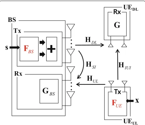
As depicted in Fig.1, we consider a two-user FD multiple-input multiple-output (MIMO) communication system, where BS operates in FD mode with two transmit anten-nas and two receive antenanten-nas, one user activates in UL mode with two transmit antennas, and the other user works in DL mode with two receive antennas. The matrix HIUI ∈ C2×2 denotes a 2× 2 Rayleigh fading channel from the UL user to the DL user, which is called an IUI
Fig. 1A full-duplex two-user MIMO communication system.FBSand FUEare designed to cancel IUI from uplink user to downlink user
channel. It is assumed that the channel state information (CSI) of the IUI channel is known to the UL user. The UL user can detect the pilot signal from the DL user when the DL user transmits a pilot signal to BS to obtain the CSI of the DL channel at the BS. Also, the UL user can use channel reciprocity characteristics because the UL and DL users are supported by the same band in the full-duplex system. This means that the CSI of the IUI channel can be known to the UL user, and the UL user can use the CSI of the IUI channel to design an IUI cancellation fil-ter. The matrices HDL ∈ C2×2 and HUL ∈ C2×2 are a DL channel from BS to the DL user and an UL channel from the UL user to BS, respectively, and both channels have Rayleigh fading characteristics. By [9,15], we assume that a self interference cancellation technique is applied and the residual self interference channel,HSI ∈C2×2, is modeled as Ricean fading channel:
vec(HSI)∼CN
K 1+Kvec
˜
H
,
1
1+KI2⊗I2
,
(1)
where ⊗means Kronecker product. We assume Ricean factor,K, is 1 and all components of deterministic channel,
˜
H, are 1 [9]. The vectorss∈C2×1andx∈C2×1denote a DL transmit symbol vector of BS and an UL transmit sym-bol vector of the UL user, respectively. Then, the received signal vector at the DL user can be expressed as
yDL=PDLHDLFBSs+
PULHIUIFUEx+nDL, (2)
and the UL received signal vector at BS is
yUL=PULHULFUEx+
σ2
SIPDLHSIFBSs+nUL, (3) wherePDLis the DL power,PULrepresents the UL power, and the matricesFBSandFUEindicate a BS pre-processing filter for DL diversity gain and an UL user pre-processing filter for IUI cancellation. In (3),σSI2 denotes a gain of the residual self interference and the vectorsnDL ∈C2×1and
nUL∈C2×1are zero mean complex Gaussian noises with varianceN0, i.e.,CN(0,N0).
3 Proposed scheme for diversity gain and IUI
cancellation
receive antennas. We assume that the channel remains constant over two symbol periods. Under the condition that the DL user sums two successive received signals for two symbol periods, BS and UE pre-processing filters are designed to achieve transmit diversity and to cancel IUI, respectively. To design pre-processing filters individually, we divide the received signal at the DL user into desired signal, ydDL, and IUI signal, yIUIDL, where ydDL means the received signal from the BS andyIUIDL denotes the received signal from the UL user.
3.1 Transmission scheme and filter design at BS for
diversity gain
In this section, we design a transmission scheme and a pre-processing filter at BS to obtain transmit diversity gain. The symbol vector,s, is transmitted at the first sym-bol period and the symsym-bol vector, ands∗, is transmitted at the second symbol period from the BS to the the DL user, where s∗ means the complex conjugate ofs. A rotation receive filter at the DL user, i.e.GUE=G, is multiplied to the complex conjugate of the second received signal vector and this vector is added to the first received signal vector. Then, the received desired signal at the DL user can be expressed as noises during two symbol periods. Since the total transmit power isPDL, the transmit power at each symbol period isPDL/2. If we setHeff =
HDL GH∗DL
, the effective DL channel matrix,Heff, is the orthogonal, i.e.HeffHeffH = HDL2FI, where(•)H denotes the conjugate transpose, •F means the Frobenius norm, and I is the identity matrix. Then, we can set Feff = malization factor, and (4) can be represented as
y=
Then, the received signal-to-noise ratio (SNR), γ, per symbol is
whereρ means transmit SNR. This received SNR is the same with the Alamouti scheme, and we can obtain the
diversity order of 4 [14]. Thus, the pre-processing filters at BS to obtain diversity gain are given as
FBS,1=
3.2 Pre-processing filter at the UL user for IUI cancellation
To cancel IUI, we design a pre-processing filter at the UL user based on NSP. If the UL user transmits the com-plex conjugate of the previous transmitted symbol at the second symbol period, the UL user can make the NSP pre-processing filter by using two symbol periods. Then, the summation of the received IUI signal at the DL user can be expressed as
whereFUE,iis the UL pre-processing filter at thei-th sym-bol period for canceling IUI, andα =
2
FUE,12F+FUE,22F represents the UL power normalization factor. If we define an effective IUI channel asHIUI,eff = HIUIFUE,1, the IUI cancellation filter of the second symbol period,FUE,2, can be designed to satisfy the following:
HIUI,eff +GH∗IUIF∗UE,2
x=0. (9)
Then,FUE,2can be expressed as
FUE,2= − the UL pre-processing filter of the first symbol period to identity matrix,FUE,1=I, (10) can be represented as
FUE,2= −
G∗HIUI
†
H∗IUI. (11)
Then, the summation of the received signal at the DL user for two symbol periods can be expressed as
yDL,1+Gy∗DL,2
noise ratio (SINR) is degraded due to IUI, and this induces BER performance loss. Also, the Alamouti scheme with interference cancellation derives only two diversity gain in our system model [16, 17]. To obtain full diversity without SNR loss in the Alamouti scheme, IUI cancella-tion is required at the UL user by a pre-processing filter. However, since the number of spatial domain of a pre-processing filter at the UL user is not larger than the rank of effective IUI channel, the UL user cannot make a pre-processing filter to cancel IUI. However, the proposed scheme achieves both IUI cancellation and full diversity gain by using the pre-processing filters at the UL user and BS, since the number of spatial and time domains of the UL user is two times the rank of the IUI channel.
3.3 Extension to the arbitrary number of antennas system
The pre-processing filter of UL user can be designed to cancel IUI regardless of the number of user antennas if the number of transmit antennas of the UL user is not smaller than that of receive antennas of the DL user. Also, the proposed BS transmission scheme can be extended to the arbitrary number of BS transmit antennas, so that it achieves 2MBST diversity gain, whereMBST is the number of BS transmit antennas. BS to theith receive antenna of DL user. Since the effec-tive channel is a form of orthogonal matrix as in Section 3.1, 2MBST diversity gain can be obtained if the pre-processing filter of BS consists of the Hermitian matrix of Heff, i.e. FBS,1 = h(1)DL
, where BS transmits two symbols
like in the case ofMBST = 2. However, the pre-processing filter of BS is hard to be extended to the case of arbitrary number of antennas of DL user. Thus, we consider on antenna selection scheme to extend our proposed scheme to the arbitrary number of user antennas. For the arbi-trary number of receive antennas of the DL user, i.e.MUER , we can select two receive antennas by using the rotation matrix. Since the proposed BS transmission scheme can make effective channel matrix become orthogonal when two receive antennas are selected, the channel gain-based antenna selection method can be used. However, inde-pendent antenna selection makes the rotation matrix vary where two receive antennas with the largest channel gains are selected. This means that DL user should inform the information of rotation matrix to UL user, and it induces
the feedback overhead. Thus, we propose a subset based antenna selection scheme to remove the feedback of rota-tion matrix. Each subset can be constructed by sequen-tially combining two consecutive antennas; the rotation matrix is expressed as a block diagonal matrix ofG:
Ge= user with the arbitrary number of receive antennas. It makes the orthogonality between two effective subchan-nels within each subset:
Heeff=
Then, each channel gain of theith subset after applying the proposed scheme can be derived as
Si=h(DLi,1) subset. Then, the subset selection scheme can be applied based on the gain of each subset:
i∗=max
i Si, (17) and the pre-processing filter of BS can be written as
FeBS,1= BS and thei∗th subset receive antennas of DL user. There-fore, DL user can detect the signal by using the antennas contained in thei∗th subset, and each received SNR can be expressed as
Although the proposed scheme has limitation in extend-ing to general multi-user environment, it is possible to increase the number of UL users if only one DL user is supported. Since the pre-processing filters to cancel IUI from each UL user are designed at each user, residual IUI of the proposed scheme does not exist regardless of the number of UL users. This means that DL user does not need to consider IUI from multiple UL users. In the case of the increase of the number of DL users, IUI can be elim-inated if additional time durations are used as much as the number of DL users. However, it is inefficient since this technique causes the performance loss of UL spectral efficiency due to the repetition transmission of the same information. Thus, the proposed scheme can be applied to the system supporting multiple UL users and one DL user.
4 Simulation results
In this section, we compare the performance of the pro-posed scheme with other FD and HD schemes in the viewpoint of BER and spectral efficiencies. As bench-marks of the HD system, regularized channel inversion (CI) [18], singular value decomposition (SVD) with water-filling [14], and Alamouti scheme are compared with the proposed scheme. Also, FD minimum mean square error (MMSE) and FD Alamouti with MSE are considered as conventional schemes of FD system to compare with the proposed scheme. In these two conventional FD schemes, IUI is canceled by using MMSE receiver at DL user. In contrast to FD MMSE where BS transmits the signal with-out any precoding scheme, BS transmits signals using
Alamouti scheme in FD Alamouti with MSE scheme. We assume that each channel gain and the noise variance are 1 except forHSI.
Figure 2 shows BER of DL streams where DL target rate are fixed to RDL = 4bps/Hz. First, we can see that BER of the proposed scheme is the lowest and the diversity order of the proposed scheme is 4. Since IUI is perfectly canceled, the BER performances of the pro-posed scheme are the same regardless of the magnitude ofPUE. However, the BER performance of FD Alamouti with MSE is degraded as the magnitude ofPUEbecomes larger since the spatial domain of the DL user should be used for IUI cancellation. This tendency is also shown in FD MMSE, but the performance of FD MMSE is worse than that of FD Alamouti with MSE since the spatial domain is not enough to cancel IUI. This causes inap-propriate operating of IUI cancellation, and residual IUI degrades the BER performance of FD MMSE schemes. Moreover, we can see that the BER performance of HD SVD with waterfilling scheme is the lowest among HD schemes, because the BER performance is affected by the minimum distance between symbols. In HD SVD scheme, since the waterfilling algorithm is applied, the distance between symbols corresponding to the small-est eigenvalue is minimum and performance degradation occurs.
Next, we analyze the achievable rate of the proposed scheme. To compare the achievable rate of the proposed scheme with those of conventional schemes, we apply the discrete rate (DR) using adaptive M-QAM modulation [19]. BPSK, 4-QAM, 16-QAM and 64-QAM modulation
schemes are used, and the target BER is set to 10−3 in all simulations. Figure3 shows the DL spectral efficien-cies of the proposed scheme and those of the various schemes based on total transmit power constraint, where UL transmit power is 15dB. First, we can see that DR of the proposed scheme is higher than those of other schemes. As mentioned in Section3, the DL user of the proposed scheme can obtain the diversity gain by the pre-processing at BS, and IUI from the UL user to the DL user can be canceled by the pre-processing at the UL user. Also, since the number of effective subchannels of the HD system based on the Alamouti scheme is half of the proposed scheme, DR of the proposed scheme is two times of the HD system with the Alamouti scheme, and the DR differences between the proposed scheme and other HD schemes are larger than 5dB. Note that the FD MMSE receiver obtains very low DL spectral efficiency compared with the proposed scheme because residual IUI degrades the DR performance when the MMSE receiver is applied. In particular, DL spectral effi-ciency of FD MMSE is almost 0 when SNRBS is smaller than 15dB since FD MMSE cannot cancel IUI appro-priately. The performance of FD Alamouti with MSE is lower than those of HD schemes in the low SNRBSregion, but an increase of the performance of FD Alamouti with MSE according to SNRBS is higher than those of HD schemes. It is because the performance degradation of FD Alamouti with MSE due to IUI becomes smaller as SNRBS is larger.
To compare the sum spectral efficiencies of the pro-posed scheme with the FD and HD schemes, we assume
that both FD and HD modes use MMSE receiver at BS for UL received signal. Then, the received SINR at BS in FD mode can be expressed as
ρU,k=
PUL 2 α
2hH UL,k
P UL 2 α
2h
UL,jhHUL,j+σSI2
PDL 2 HSIFBS,1F
H
BS,1HHSI+N0I −1
hUL,k,
(20)
where hUL,k means thek-th column ofHUL andk = j. The residual self interference is treated as background noise [9], and the UL pre-processing filter of the first sym-bol period,FUE,1, is set to be an identity matrix. Figure4 illustrates the sum spectral efficiencies of both modes when the residual self interference gain exists in FD BS, where UL transmit power is 15dB. The performance gaps between the proposed scheme and the HD schemes are smaller than that of DL spectral efficiency. It results from the fact that the UL rate of the proposed scheme is lower than those of HD schemes. In the proposed scheme, the UL transmit power per transmission is half of that of the HD mode because additional transmission is required to obtain a null space of the IUI channel, so that 3 dB perfor-mance degradation occurs. The residual self interference in BS also degrades the performance of the proposed scheme. In low SNRBSregion, the performance of the pro-posed scheme is the lowest since UL spectral efficiency of the proposed scheme is the worst. However, the perfor-mance improvement of the proposed scheme according to SNRBS is largest since the dominance of DL spectral efficiency increases as SNRBS becomes higher. Note that the sum spectral efficiency of FD Alamouti with MSE is
Fig. 4The sum spectral efficiencies of the proposed scheme and the existing schemes according to BS transmission power
higher than that of the proposed scheme whenSNRBS = 30 dB. The reason for this is that the maximum value of the sum spectral efficiency of FD Alamouti with MSE is higher than that of the proposed scheme due to the per-formance difference between the UL spectral efficiency of each scheme. Also, the sum spectral efficiency of the proposed scheme is declined in the high SNRBS region, because the increase of SNRBSarouses the increase of the magnitude of the residual self interference, while DL rate reaches to a saturation value as shown in Fig.3. FD MMSE scheme has almost the same sum spectral efficiencies in low SNRBSregion whereσSI2 is smaller than−30 dB. This means that DL spectral efficiency is almost 0 because of IUI. The reason for the performance degradation of FD MMSE whenσSI2 = −15 dB andSNRBS is smaller than 20 dB is that residual self interference interferes to UL spectral efficiency while DL spectral efficiency is almost 0. Figure5shows that the sum spectral efficiencies of the proposed scheme and other schemes according to UE transmit power, where BS power is 20 dB. It can be seen that the gap between the performance whenσSI2 = −45 dB and the performance whenσSI2 = −30 dB is small in FD schemes, because the magnitude of the residual self interference is sufficiently smaller than the noise power. Thus, the effects of the residual self interference of these two cases are trivial. However, the performance degrada-tion due to residual self interference is large whenσSI2 = −15 dB, since the magnitude of the residual self inter-ference is larger than the noise power. This means that self interference should be mitigated lower than the noise
level. Also, it can be seen that the performance of the FD Alamouti with MSE is better than that of the proposed scheme in high SNRUE region, since the dominance of the UL spectral efficiency about sum spectral efficiency is larger than that of DL spectral efficiency. Note that the sum spectral efficiencies of FD schemes except for the proposed scheme are decreased as SNRUEbecomes larger in the low SNRUE region, because IUI degrades the DL spectral efficiency. Also, it can be seen that the sum spec-tral efficiencies of regularized CI and HD Alamouti are almost same, because the DL spectral efficiency of regu-larized CI and HD Alamouti are almost same when SNRBS is 20 dB as shown in Fig.3.
Figure 6 represents the performance degradation of the proposed scheme as increase of σSI2. It shows that if the self interference is not canceled to a certain degree, the performance of the proposed scheme is not guaranteed. Thus, we can conclude that a proper self interference cancellation scheme is required to obtain higher performance of FD mode.
5 Conclusion
Fig. 5The sum spectral efficiencies of the proposed scheme and the existing schemes according to UE transmission power
symbol periods with that of DL users and this constraint degrades the performance of the proposed scheme when the number of DL user is increased. Thus, the general-ization of this scheme should be studied to support more than two users.
6 Methods/Experimental
The purpose of this study is to eliminate IUI to increase the spectral efficiency of the FD system. The system
consists of one FD BS and two HD users where one HD user operates the UL mode and another HD user acti-vates the DL mode. The channels between each device are assumed as a Rayleigh fading channel model, and it is assumed that the residual self interference of BS after applying self interference cancellation scheme has Ricean fading characteristics. Since the number of the trans-mission of FD systems is twice of that of HD systems, transmission power of FD schemes is half of that of HD
schemes. Instead, the modulation order of FD schemes is half of that of HD schemes when BER performance is eval-uated. Spectral efficiency is calculated by using adaptive M-QAM modulation, and the modulation order of each transmission is decided based on received SINR.
Abbreviations
BER: Bit error rate; BPSK: Binary phase shift keying; BS: Base station; CI: Channel inversion; CSI: Channel state information; DL: Downlink; DR: Discrete rate; FD: Full duplex; FDD: Frequency division duplex; HD: Half duplex; IUI: Inter user interference; MIMO: Multiple input multiple output; MMSE: Minimum mean square error; MSE: Mean square error; NSP: Null space processing; QAM: Quadrature amplitude modulation; SINR: Signal to interference and noise ratio; SNR: Signal to noise ratio; SNS: Social networking services; TDD: Time division duplex; UE: User equipment; UL: Uplink
Acknowledgements
This research was supported by LG Electronics Secho Research and Development Campus.
Funding
This work was supported by LG Electronics Co. Ltd.
Authors’ contributions
HN has contributed 70% of the work, and the rest is contributed by CL. Both authors read and approved the final manuscript.
Competing interests
The authors declare that they have no competing interests.
Publisher’s Note
Springer Nature remains neutral with regard to jurisdictional claims in published maps and institutional affiliations.
Author details
1The Department of Electrical and Electronic Engineering, Yonsei University,
C418, Seoul, 03722, South Korea.2The Department of Electrical and Electronic
Engineering, Yonsei University, C527, Seoul 03722, South Korea.
Received: 6 March 2018 Accepted: 19 June 2018
References
1. JI Choi, M Jain, K Srinivasan, P Levis, S Katti, inAchieving single channel, full duplex wireless communication. Proceedings of the Sixteenth Annual International Conference on Mobile Computing and Networking. MobiCom ’10 (ACM, New York, 2010), pp. 1–12
2. A Sabharwal, P Schniter, D Guo, DW Bliss, S Rangarajan, R Wichman, In-band full-duplex wireless: challenges and opportunities. IEEE J. Sel. Areas Commun.32(9), 1637–1652 (2014)
3. S Li, RD Murch, VKN Lau, inLinear transceiver design for full-duplex multi-user MIMO system. 2014 IEEE International Conference on Communications (ICC) (IEEE, Sydney, 2014), pp. 4921–4926
4. P Xing, J Liu, C Zhai, Z Yu, Self-interference suppression with imperfect channel estimation in a shared-antenna full-duplex massive MU-MIMO system. EURASIP J. Wirel. Commun. Netw.2017(1), 18 (2017)
5. T Riihonen, S Werner, R Wichman, Mitigation of loopback self-interference in full-duplex MIMO relays. IEEE Trans. Signal Process.59(12), 5983–5993 (2011)
6. DW Bliss, PA Parker, AR Margetts, inSimultaneous transmission and reception for improved wireless network performance. 2007 IEEE/SP 14th Workshop on Statistical Signal Processing (IEEE, Madison, 2007), pp. 478–482
7. H ElSawy, A AlAmmouri, O Amin, MS Alouini, inCan uplink transmissions survive in full-duplex cellular environments?. European Wireless 2016; 22th European Wireless Conference (VDE, Oulu, 2016), pp. 1–6
8. X Wang, D Zhang, K Xu, W Ma, On the energy/spectral efficiency of multi-user full-duplex massive MIMO systems with power control. EURASIP J. Wirel. Commun. Netw.2017(1), 82 (2017)
9. D Nguyen, LN Tran, P Pirinen, M Latva-aho, On the spectral efficiency of full-duplex small cell wireless systems. IEEE Trans. Wirel. Commun.13(9), 4896–4910 (2014)
10. P Xing, J Liu, C Zhai, X Wang, L Zheng, Spectral efficiency of the in-band full-duplex massive multi-user multiple-input multiple-output system. IET Commun.11, 490–4988 (2017)
11. G Yu, D Wen, F Qu, Joint user scheduling and channel allocation for cellular networks with full duplex base stations. IET Commun.10, 479–4867 (2016)
12. R Palit, K Naik, A Singh, Anatomy of WiFi access traffic of smartphones and implications for energy saving techniques. Int. J. Energy Inf. Commun.
3(1), 1–16 (2012)
13. ITU-R M.2370, IMT traffic estimates for the years 2020 to 2030 (2015) 14. A Paulraj, R Nabar, D Gore,Introduction to Space-Time Wireless
Communications. (Cambridge University Press, New York, 2003) 15. M Duarte, C Dick, A Sabharwal, Experiment-driven characterization of
full-duplex wireless systems. IEEE Trans. Wirel. Commun.11(12), 4296–4307 (2012)
16. AF Naguib, N Seshadri, AR Calderbank, inApplications of space-time block codes and interference suppression for high capacity and high data rate wireless systems. Conference Record of Thirty-Second Asilomar Conference on Signals, Systems and Computers (Cat. No.98CH36284), vol. 2 (IEEE, Pacific Grove, 1998), pp. 1803–18102
17. WM Younis, AH Sayed, N Al-Dhahir, Efficient adaptive receivers for joint equalization and interference cancellation in multiuser space-time block-coded systems. IEEE Trans. Signal Process.51(11), 2849–2862 (2003) 18. VK Nguyen, JS Evans, inMultiuser transmit beamforming via regularized
channel inversion: a large system analysis. IEEE GLOBECOM 2008 - 2008 IEEE Global Telecommunications Conference (IEEE, New Orleans, 2008), pp. 1–4