UNCLASSIFIED
, .0. 31 P2-2FSQ7-2
BASIC THEORY
OF COMPUTERS
ANjFSQ-7
COMBAT DIRECTION CENTRAL
1
April 1957
The work reported in this document was performed under a government con-tract; information contained herein is of a proprietary nature. ALL INFOR-MATION CONTAINED HEREIN SHALL BE KEPT IN CONFIDENCE. No information shall be divulged to persons other than IBM employees authorized by the nature of their duties to receive such information or individuals or organizations who are authorized in writing by the Department of Engineering or its appointee to receive such information. GOVERNMENT RELEASE MUST BE OBTAINED THROUGH THE IBM PATENT DEPARTMENT BEFORE THIS INFORMATION MAYBE USED FOR COMMERCIAL APPLICATIONS.
MILITARY PRODUCTS DIVISION
INTERNATIONAL BUSINESS MACHINES CORPORATION _ _ _ _ _ - - 1 KINGSTON, NEW YORK
UNCLASSIFIED
UNCLASSIFIED T.O. 31P2-2FSQ7-2
Reproduction for non-military use of the information or illustrations contained in this publi-cation is not permitted without specific approval of the issuing service (BuAer or USAF). The policy for use of classified publications is established for the Air Force in AFR 205-1 and for the Navy in Navy Regulations, Article 1509.
; r - - - L l S T OF REVISED P A G E S - - - .
A
INSERT LATEST REVISED PAGES. DESTROY SUPERSEDED PAGES.
NOTE: The portion of the text affected by the current revision is indicated by a vertical rule in the left margin of a left-hand page and in the right margin of a right-hand page.
*The asterisk indicates pages revised, added or deleted by the current revision.
PARTS 1 to 5
Heading
UNCLASSIFIED
10.
31 P2-2FSQ7-2CONTENTS
PART 1
INTRODUCTIONCHAPTER 1
PURPOSE AND P'LAN OF MANUAL1.1 General.
1.2 Division of Manual into Parts
CHAPTER 2
THE NATURE AND FUNCTIONS OFCOMPUTING MACHINES
2.1
2.1.1
2.1.2
2.1.3
2.2
2.2.1
2.2.2
2.3
2.3.1
2.3.2
2.3.3
2.3.4
2.4
2.4.1
2.4.2
What Computing Machines Are.
Definition
Example of Machine Data Processing .
Arithmetic and Control Operations .
The Need for High-Speed Computers.
General
Air Defense Needs
Basic Classes of Computing Machines ... .
Basis of Classification
Digital Computers
Analog Computers
Physical Size of Computers .
History of Computers.
Early Computing Machines
Advent of Large, High-Speed Computers .
CHAPTER 3
ELEMENTS AND COMPONENTS REQUIRED3.1
3.2
3.2.1
3.2.1.1
3.2.1.2
3.2.1.3
3.2.2
BY DIGITAL COMPUTERS
The Language Used by Digital Computers .
Digital Computer Elements.
Data Processing
General
Example of Simple Data Processing .
Machine Requirements for Data Processing .
Input Element .
Page
1
1
1
1
3
3
3
3 4 5 5 5 5 5 5 5
6
6
6
6
9
9
9
9
9
10
10
11
Contents
ii
Heading
UNCLASSIFIED T.O. 31P2-2FSQ7-2
CONTENTS
(cont'd)
Page
3.2.3 Output Element ... 11
3.2.4 Arithmetic Element ... 11
3.2.5 Storage Element ... 12
3.2.6 3.2.7 3.2.8 3.2.9 Control Element General Organization ... . General Operation Summary ... 13
... 14
... 14
... 16
PART 2
COMPUTER ARITHMETIC . ... . ... 17,CHAPTE'R 1
INTRODUCTION ... 1717 17 1.1 1.2 1.3 Computers and Information Possible Number Systems Which Number System Is Best 17
CHAPTER 2
NUMBER SYSTEMS .... 1919 19 19 2.1 2.1.1 2.1.2 2.1.3 2.1.4 2.1.5 2.2 2.3 2.3.1 2.3.2 2.3.3 2.3.4 2.4 2.4.1 2.4.2 2.4.3 2.4.4 Decimal Numbers . General ... . Positional Notation Radix ... ... 19
Counting . . ... , ... , .. .. . . .. . . .. . 19
Expression of a Decimal Number . 19 The General Expression for a Number ... ... 20
Binary Numbers General 20 20 Binary Counting ... . ... " ... , .. .. . ... .. . ... . . . 20
General Meaning of a Binary Number ... 21
Generating Binary Numbers ... 21
Octal Numbers ... 21
General 21 Octal Counting ... 21
General Meaning of an Octal Number ... 22
Use of Octal Numbers ... ... 22
UNCLASSIFIED
PARTS 1
to
5Heading
UNCLASSIFIED 1.0. 31 P2-2FSQ7-2
CONTENTS
(cont'd)
CHAPTER 3
RADIX CONVERSION3.1 Introduction
3.2 General Method
3.3 Binary to Decimal Conversion
3.4 Decimal to Binary Conversions
3.4.1 General Method
3.4.2 Radix Subtraction Method
3.4.3 Division - Multiplication Method .
3.5 Octal to Decimal Conversion
3.6 Decimal to Octal Conversion
3.6.1 General Method
3.6.2 Radix Subtraction Method
3.6.3 Multiplication - Division Method
3.7 Octal to Binary Conversion
3.7.1 General Method
3.7.2 Inspection Method
3.8 Binary to Octal Conversion .
3.8.1 General Method
3.8.2 Inspection Method
CHAPTER 4
BINARY ARITHMETIC4.1 Addition
4.1.1 General Rules
4.1.2 Addition of Binary Numbers
4.2 Binary Subtraction
4.2.1 General
4.2.2 Direct Subtraction .
4.2.3 Complementing Method in Binary Subtraction ..
4.2.3.1
4.2.3.2
4.2.3.3
4.2.3.4
4.2.3.5
4.2.3.6
General
Modulus
Derivation of Complement Method of Subtraction.
Generation of l's Complement.
l's Complement Subtraction
Generation of 2's Complements
Contents
Page
23
23
23
23
23
23
24
25
26
27
27
27
28
28
28
29
29
29
29
31
31
31
31
32
32
32
32
32
32
33
33
33
34
Contents
jv
Heading
4.2.3.7
4.2.3.8
4.2.3.9
4.3
4.3.1
4.3.2
4.3.3
4.4
4.4.1
4.4.2
4.4.3
4.4.3.1
4.4.3.2
4.4.3.3
4.4.4
UNCLASSIFIED
T.O. 31 P2-2FSQ7-2
CONTENTS (cont1d)
2's Complement Subtraction
Binary Sign Conventions ...
Page
... 34
... 35
Comparison of l's and 2's Complement Subtraction. ... 35
Binary Multiplication 36
General Method . 36
Add and Shift Multiplication ... . 36
Multiplication (or Division) of Negative Numbers . 36
Binary Division.
General
Direct Division
Division by Subtract and Shift Methods .
General
Restoring Method .
Nonrestoring Method
Nonrestoring Division Using Complement Subtraction
36
36
... 36
37
37
37
.... 38
39
CHAPTER 5
OCTAL ARITHMETIC OPERATIONS. 41 4141
42
42
42 5.1 General
5.2 Octal Addition
5.3 Octal Subtraction
5.4 Octal Multiplication ...
5.5 Octal Division.
CHAPTER 6
NUMBER REPRESENTATION IN A COMPUTER 456.1
6.2
6.3
6.4
6.5
6.6
Introduction
Word Size
Fixed and Floating Point Computers .,.
Precision and Accuracy ... .
Positional and Absolute Significance .. .
Scaling
PART
3
COMPUTER CIRCUITS AND DEVICES.CHAPTER 1
INTRODUCTION1.1 Information Signals
UNCLASSIFIED
... 45
45
45
46
46
46
. ... 49
49
49
Heading
1.1.1
1.1.2
1.1.3
1.1.3.1
1.1.3.2
1.1.3.3
1.1.4
1.1.4.1
1.1.4.2
1.1.5
1.2
1.2.1
1.2.1.1
1.2.1.2
1.2.1.3
1.2.2
UNCLASSIFIED
10. 31 P2-2FSQ7-2
CONTENTS
(cont1d)
V oltage Level Representation
Pulse Representation
Transmission Methods
Parallel
Serial
Comparison of Methods.
Timing
Parallel Transmission
Serial Transmission
No-Signal Condition
Switching Logic
Logic Operations
OR Logic ..
AND Logic
NOT Logic
Circuit Logic
...
CHAPTER 2
SWITCHING AND SMALL-SCALE2.1
2.1.1
2.1.2
2.1.3
2.1.4
2.1.5
2.1.6
2.2
2.2.1
2.2.1.1
2.2.1.2
2.2.1.3
2.2.1.4
2.2.2
2.2.3
2.2.3.1
STORAGE CIRCUITS ... .
Computer Logic Circuits ..
Relay Logic Circuits.
Diode Logic Circuits.
Vacuum Tube Logic Circuits ...
Transistor Logic Circuits
Magnetic Core Logic Circuits
Matrices
Small-Scale Storage Circuits ... .
Bistable Circuits
Relay Storage
Vacuum Tube Flip-Flops ....
Transistor Flop-Flops
Dynamic Flip-Flops
Delay Circuits
Word-Length Registers
Storage Registers
Page
49
50
50
50
51
51
52
52
52
53
53
53
53
54
54
55
57 57 57
59
62
64
66
70
71 71 73
73
74
75 76
76
76
Contents
Contents
vi
Heading
2.2.3.2
UNCLASSIFIED
T .0.
31 P2-2FSQ7-2CONTENTS
(cont'd)
Shifting Registers ... .
Page
79
2.3 Electrical Considerations and Nonlogic Circuits ... 81
2.4 Circuit Packaging ... .. ... 83
CHAPTER 3
ARITHMETIC AND CONTROL .... ... 853.1
3.1.1
3.1.2
3.2
3.2.1
3.2.2
3.3
3.4
3.4.1
3.4.2
3.5
3.6
3.6.1
3.6.2
3.6.2.1
3.6.2.2
Counting .. ... ... ... ... ... 85
Binary Counters
Ring Counters
Addition
Adders
Accumulators
Subtraction
Multiplication
Parallel Methods .
Serial Methods
Division
Control Circuitry
Program Control
Operation Control
Synchronous Control
Asynchronous Control
85 87
... 88
88
91
93
94
97
100
103
107
107
109
109
111
CHAPTER 4
LARGE-SCALE STORAGE AND MEMORY ... . 1134.1
4.2
4.2.1
4.2.2
4.2.3
4.3
4.4
4.5
4.5.1
4.5.2
Requirements of Memory Element
Magnetic Storage
Magnetic Tapes ....
Magnetic Drums
Magnetic Cores
Electrostatic Storage ... ..
Acoustic Delay Line' Storage .
Mechanical Storage ... .
Punched Hole Storage
Control Panel Storage .
UNCLASSIFIED
113
114
115
116
118
.... 121
121
122
122
123
PARTS 1
to
5Heading
UNCLASSIFIED T.O. 31P2-2FSQ7-2
CONTENTS
(cont'd)
CHAPTER 5
INPUT-OUTPUT EQUIPMENT5.1
5.1.1
5.1.2
5.2
5.2.1
5.2.2
5.2.2.1
5.2.2.2
5.2.2.3
5.2.3
5.2.3.1
5.2.3.2
5.2.3.3
5.2.3.4
5.2.4
5.2.5
5.2.6
Equipment, General
Introduction
Definition of Input-Output Devices .
Description of Input-Output Equipment .
General
Tapes and Tape-Handling Equipment.
General
Paper Tape Equipment
Magnetic Tape and Tape-Handling Equipment
Card-Handling Equipment
General
Cards and Card-Punch Equipment.
Card Reader
Line Printer.
Typewriter
Visual Displays
Other Input-Output Equipment
PART 4
COMPUTER ORGANIZATIONCHAPTER 1
INTRODUCTION1.1
1.2
1.2.1
1.2.2
1.2.2.1
1.2.2.2
1.2.2.3
1.2.2.4
1.2.2.5
1.2.2.6
1.2.2.7
General
Sample Computer Description.
Requirements
General Description
Analog or Digital .
Fundamental Elements
Program Control.
Single Address or Multiple Address
Word Length
Arithmetic
Type of Logic
Page
125
125
125
125
125
125
125
125
125
125
126
126
127
127
127
128
128
130
133
133
133
133
133
133
133
134
136
136
138
138
138
Contents
Contents
viii
Heading
1.2.2.8
1.2.2.9
UNCLASSIFIED 1.0. 31 P2-2FSQ7-2
CONTENTS
(cont'd)
Input-Output System
Summary of General Considerations
CHAPTER 2
SAMPLE SYSTEM STORAGEPage
138
138
2.1 Introduction ... . 139
139
2.2
2.3
2.4
2.5
2.5.1
2.5.2
2.5.3
2.5.4
2.5.5
2.6
2.6.1
2.6.2
2.6.3
2.7
2.7.1
2.7.2
2.7.3
2.7.3.1
2.7.3.2
2.7.3.3
2.7.3.4
General Requirements of a Storage System .
Types of Storage .
Types of Storage in Sample System ... .
General Requirements of Sample Computer Direct Access Memory ... .
Access
Size
Storage Medium
Memory Controls
Summary of Requipments
Magnetic Core Storage .
Operation of Array
Sample Computer Memory Element Operation ."
Operation of Memory in Computing System .
Auxiliary Memory
General
Choice of Auxiliary Memory Medium
Operation of Sample Computer Auxiliary Memory .
General
System Operation
Program Operation
Operation of Direct Access and Auxiliary Memory ...
CHAPTER 3
CONTROL3.1
3.1.1
3.1.2
3.1.2.1
3.1.2.2
3.1.2.3
Basic Control Assumption ... .
Sequential Operation
Types of Control ....
Synchronous Operation
Asynchronous Operation
Synchronous-Asynchronous Combinations .
UNCLASSIFIED
... 139
139
139
139
139
140
141
141
141
141
141
143
145
146
146
146
146
146
147
147
149
151
151
151
151
151
151
151
PARTS 1 to 5
Heading
3.1.3
3.1.4
3.1.5
3.2
3.2.1
3.2.2
3.2.2.1
3.2.2.2
3.2.3
3.3
3.4
3.4.1
3.4.1.1
3.4.1.2
3.4.1.3
3.4.2
3.4.2.1
3.4.2.2
UNCLASSIFIED T.O. 31P2-2FSQ7-2
CONTENTS
(cant/d)
Coding
Basic Control Element Functions. Program Time; Operate Time .
Operation of Sample Computer Control . General
Program Time . Program Sequencing . Instruction Decoding Operate Time
Control Element Operation .
Variation of Program by Control Element . Changing Program Sequence
General
Conditional Branch . . Unconditional Branch Alteration of Instructions General
Index Registers
CHAPTER 4
ARITHMETIC ELEMENT4.1
4.2
4.3
4.4
4.4.1
4.4.2
4.4.2.1
4.4.2.2
4.4.2.3
4.4.2.4
4.4.2.5
4.4.2.6
General
Arithmetic Element Purpose.
Requirements of An Arithmetic Element
Operation of Sample System Arithmetic Element . Introduction .
Arithmetic Element Description General
Addition Subtraction Multiplication Division Shifting
CHAPTER 5
INPUTS AND OUTPUTS5.1 General
Page
151
152
152
152
152
152
152
153
155
156
157
157
157
157
157
158
158
159
161
161
161
161
162
162
162
162
162
164
165
168
170
171
171
Contents
Contents
x
Heading
5.2
5.3
5.3.1
5.3.2
5.3.2.1
5.3.2.2
5.3.2.3
5.4
5.4.1
5.4.2
5.5 5.6
5.6.1
5.6.2
5.6.2.1
5.6.2.2
5.7
5.7.1
5.7.2
5.7.3
UNCLASSIFIED
T .0.
31 P2-2FSQ7-2CONTENTS
(cont1d)
Sample System Considerations
10 Buffer Drum .
Purpose ... .
Drum Operation.
General
Status Control Operation
Program Operation
Automatic Inputs
General ..
Operation
Typewriter Input ...
Automatic Outputs
General
Operation
Program Operation
System Operation
Display Output ..
General
Program Operation
System Operation
Page
172
172
172
172
172
172
173
174
174
174
174
175
175
175
175
.... 175
176
... 176
176
176
CHAPTER 6
OPERATION OF THE SAMPLE SYSTEM .... 179179
179
179 6.1
6.2
6.3
General
Program Loading
Loading and Processing Data
PART 5
PRINCIPLES OF PROGRAMMING 181CHAPTER 1
INTRODUCTION ... . 1811.1
1.2
1.3
General ... .
Program Definition .
Necessity for Programming
CHAPTER 2
TECHNIQUES OF PROGRAMMING2.1 General
UNCLASSIFIED
181
181
... _181
183
... 183
PARTS 1 to 5
Heading
2.2
2.2.1
2.2.2
2.2.3
2.2.4
UNCLASSIFIED
T.O.
31P2-2FSQ7-2CONT.ENTS
(cont/d)
Program Preparation
Problem Analysis
Organization
Coding
Testing
CHAPTER 3
PROGRAM EXAMPLES3.1
3.2
3.2.1
3.2.2
3.2.3
3.2.4
3.2.5
3.3
3.3.1
3.3.2
3.3.3
General
Straight-Line Program
General
Statement of Problem .
Problem Analysis
Organization
Coding
Logical Program.
General
Statement of Problem .
Problem Analysis
3.3.4 Organization
3.3.5 Coding
3.4 Iterative Program
3.4.1 General
3.4.2 Statement of Problem .
3.4.3 Problem Analysis
Organization
Coding
3.4.4
3.4.5
3.5
3.5.1
3.5.2
3.5.3
Indexed Iterative Program .
General
Statement of Problem ... .
Organization
3.5.4 Coding
CHAPTER 4
TYPES OF PROGRAMS4.1 General
4.2 Examples
Page
183
183
183
183
184
185
185
185
185
185
185
186
186
186
... 186
186
186
187
187
192
192
192
192
192
192
194
194
194
194
196
199
199
199
Contents
Contents
List of Illustrations
UNCLASSIFIED T.O. 31P2-2FSQ7-2
xii
Heading
4.2.1
4.2.2
4.2.3
4.2.3.1
4.2.3.2
4.2.3.3
4.2.4
4.2.5
4.2.5.1
4.2.5.2
CONTENTS
(cont'd)
Master Program
Subroutines ... ' ... .
Utility Programs
General ... .
Symbolic Program
Assembly Programs
Operational Programs
Maintenance Programs ...
Reliability Programs
Diagnostic Programs ... .
Page
199
199
199
199
199
200
200
200
200
200
CHAPTER 5
CAPABILITIES AND LIMITATIONS OF COMPUTER .... 2015.1
5.2
5.3
5.4
5.5
Problem-Solving Capability ... . 201
201 Speed ... .
Ease of Programming and Operation
Reliabili ty
Conclusion
... 201
202
202
INDEX ... .
. ... 205LIST OF ILLUSTRATIONS
Figure Title Page
1-1 The AN/FSQ-7 3
1-2 Data Processing - Finding the Largest of Three Numbers, A, B, and C... ... . ... 4
1-3 Digital and Analog Representations of the Number 34 ... 6
1-4 The Abacus - The Number Represented by the Position of the Beads is 34 ... 7
1-5 Numbers and Control Instructions Represented in the Form of Voltages ... ... ... .... ... ... ... ... 10
1-6 Input Element - This Element Receives Information and Converts it into Usable Form ... 11
1-7 Output Element - This Element Converts Computer's Answer to the Problem into Form Usable by External Output Devices. . ... 12
UNCLASSIFIED
PARTS 1 to 5 UNCLASSIFIED T.O. 31 P2-2FSQ7-2
LIST OF ILLUSTRATIONS
(cont'd)
Figure Title
1-8 Arithmetic Element - Data Enters and Is Processed by This Element
1-9 Storage Element - Possible Address and Contents Correlation .
1-10 Typical Instructions from Control Element.
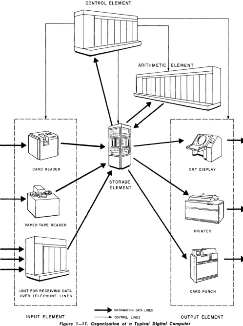
1-11 Organization of a Typical Digital Computer .
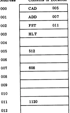
1-12 Contents of Memory for Solution of the Problem: 512
+
608 = ? . 2-1 Computer Word3-1 Common Number Signals.
3-2 Parallel Transmission of Numbers
3-3 Serial Transmission of Numbers .
3-4 Timing of Serial Numbers
3-5 OR Situation Symbolized ..
3-6 OR Function
3-7 AND Function
3-8
3-9
NOT Function (Inversion)
AND NOT Diagrammed ..
3-10 Inhibit Function ...
3-11 Logic of Doorbell Situation ...
3-12 Doorbell Circuit, Showing Logic .
3-13 Complete Doorbell OR Circuit ..
3-14 Relay OR Circuit.
3-15 Relay AND Circuit ...
3-16 Relay AND NOT Circuit.
3-17 Sample Relay Logic Combination ..
3-18 Diode OR Circuit ..
3-19 Diode AND Circuit
3-20 Use of Compensating Delay.
3-21 Diode Inhibit Circuit for Pulse Signals .
3-22 Sample Logic Circuit Combination
3-23 3-24
Vacuum Tube NOT Circuit ... .
Vacuum Tube OR Circuit
3-25 Multiple-Input OR Arrangements
3-26 Vacuum Tube AND Circuit .
3-27 Gate Circuit .
3-28 Basic Transistor Switch
List of Illustrations
Page
12 13 13 15 16
45 49 51
51 52
53 54 54 54 54 55 55
55 56
57 58 58
59 59 60 60 61 62 62
63 63 64
65 65
List of Illustrations
Figure
3-29
3-30
3-31
3-32
3-33
3-34
3-35
3-36
3-37
3-38
3-39
3-40
3-41
3-42
3-43
3-44
3-45
3-46
3-47
3-48
3-49
3-50
3-51
3-52
3-53
3-54
3-55
3-56
3-57
3-58
3-59
3-60
3-61
3-62
xiv
UNCLASSIFIED
T.O.
31P2-2FSQ1-2LIST OF ILLUSTRATIONS
(cont'd)
Title
Transistor OR Circuit
Transistor AND Circuit ... .
Sample Transistor Circuit Arrangement .
Page
65
65
66
Tape Core Construction ... . ... 66
Magnetic Core and Hysteresis Loop.
Magnetic Core OR Arrangement ...
Interconnection of Magnetic Cores .
Magnetic Core Inhibit Arrangement.
Effect of Two Inhibit Inputs ... .
Magnetic Core AND Circuit .
Diode Matrix ... ..
Matrix of Logic Circuits
Basic Bistable Storage Circuit ...
Complete Logic Circuit Flip-Flops.
Flip-Flop Circuit Symbols
Relay Storage Arrangement .
Basic Vacuum Tube Flip-Flop .
Transistor Flip-Flop
67
68
68
68
69
69
70
70
71
72
72
73
73
74
Dynamic Flip-Flop ... ... ... 75
Use of Dynamic Flip-Flop .
Basic Delay Line Section.
Parallel Flip-Flop Storage Register
Parallel Core Register .
Circulating Register for Serial Words
Core Register for Serial Words .
Core Shifting Register .
Flip-Flop Shifting Register
Register Using Ripple Shift .
Typical Pulse in Computer Circuitry ... .
Circuits Packaged in Plu,ggable Unit .. .
75
76
... 77
77
78
79
79
80
82
82
84
Basic Flip-Flop Counter ... .. .. ... 86
Higher Speed Counting Register ... .. 86
Ring Counter Stages ... ... 87
Using Ring Counters in Tandem . 88
UNCLASSIFIED
PARTS 1 to 5 UNCLASSIFIED T.O. 31 P2-2FSQ7-2
LIST OF ILLUSTRATIONS
(cont'd)
Figure Title
3-63 Half Adder 3-64 Full Adder
3-65 Parallel Adders
3-66 Full Adders for Serial Operation
3-67 Serial Accumulator
3-68 Parallel Accumulator
3-69 Stage of Accumulator With Faster Carry Propagation.
3-70 Arrangement for Transfer of True or l's Complement Number.
3-71 Shifting Register Feeding Accumulator for Multiplication.
3-72 Gating and Shifting by Switching .
3-73 Shifting Accumulator Used for Multiplication .
3-74 Shifting by Delay of Serial Number.
3-75 Shifting With Circulating Registers .
3-76 Basic Arrangement for Serial Multiplication
3-77 Serial-Parallel Multiplication.
3-78 Shifting Accumulator Used for Division .
3-79 Instruction Control
3-80 Synchronous Control of Operations .
3-81 Asynchronous Control of Operations.
3-82 Delay Lines for Asynchronous Control.
3-83 Magnetic Head .
3-84 Basic Tape Storage Arrangement
3-85 Storage on Magnetic Drum .
3-86 Address Selection of Drum Registers .
3-87 Writing and Reading by Status ...
3-88 Core Memory Plane
3-89 Stacked Memory Planes
3-90 Acoustic Delay Line
3-91 Control Panel
3-92 Paper Tape with Associated Reader and Punch.
3-93 Magnetic Tape Drive Unit ... .
3-94 Cord Arranged in Hollerith Code Format .
3-95 Computer Entry Punch
3-96 Computer - Operated Card Punch.
List of Illustrations
Page
89
90 90 91 91
92 93 95 98
99 100 101 101
101 103 106
108 110 111 112 114 116 117 117 118 118 120 122 123 126 127 128 129 130
List of Illustrations
Figure
3-97
3-98
3-99
3-100
4-1
4-2
4-3
4-4
4-5
4-6
4-7
4-8
4-9
4-10
4-11
4-12
4-13
4-14
4-15
4-16
4-17
4-18
4-19
4-20
4-21
4-22
4-23
4-24
5-1
5-2
5-3
5-4
5-5
xvi
UNCLASSIFIED T.O. 31 P2-2FSQ7-2
LIST OF ILLUSTRATIONS
(cont'd)
Title
Card Reader
Line Printer ...
Visual Display Unit
Display Tube, Simplified Diagram.
Elements of the Sample Computer ..
Word Format
Storage Function Relationships
4-Location 3-Bit Register Core Array
Read and Write Operation of Memory ...
Page
130
131
132
132
134
137
140
142
144
Contents of Memory During Execution of Program. 146
Auxiliary Memory Drum . 147
Auxiliary Memory Drum System Operation 148
Program Time: Operate Time, Time Pulse Distributor Operation. 153
Instruction Selection, Readout, and Decoding (Program Time) 154
Instruction Decoding (Operate Time)
Control Operations for ADD Instruction .
155
156
Conditional Branch Instruction Execution (Branch on Full Minus) 157
Address Modification by Index Register
Arithmetic Element Information Flow ...
159
163
Add Instruction Arithmetic Control (Operate Time) 164
Subtract Instruction Arithmetic Control (Operate Time) 165
Contents of A-Register, B-Register, and Accumulator during Mul-tiplication ... .. ... ... 166
Contents of A-Register, B-Register, and Accumulator during Division 169
Status Control of Drum .
Input System
Manual Input
Automatic Output System
Display Output
Flow Chart for Straight-Line Program.
Flow Chart, Coded Straight-Line Program.
Flow Chart for Logical Program
173
174
175
177
177
183
186
... 188
Flow Chart, Coded Logical Program, Preliminary Layout ... 189
Flow Chart, Coded Logical Program, Final Layout. . 190
UNCLASSIFIED
PARTS 1 to 5 UNCLASSIFIED T.O. 31 P2-2FSQ7-2
LIST OF ILLUSTRATIONS
(cont'd)
List of Illustrations List of Tables
Figure Title Page
5-6 Flow Chart for Iterative Program
5-7 Coded Iterative Program
5-8 Flow Chart for Indexed Iterative Program .
5-9 Coded Indexed Iterative Program
Table
1-1 2-1
2-2 2-3
LIST OF TABLES
Title
Some Possible Instruction
Positive and Negative Power of 2 .
Positive and Negative Power of 8
Octal Addition - Subtraction
192 193 195 197
Page
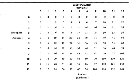
14 24 27 41 2-4 Octal Multiplication - Division . 43 3-1 Output Changes of Tandem Ring Counters. 88 3-2 Word Shifts in Circulating Registers. 101 3-3 Timing of Serial Multiplication 102 4-1 Summary of Differences Between Read and Write Cycles of a Read
5-1 5-2
5-3 5-4 5-5 5-6 5-7
Operation and a Write Operation 145
Basic Computer Instructions
Straight-Line Program
Branching Instructions
Logical Program
Iterative Program
Indexing Ins tructions
Indexed Iterative Program .
185
187
187
191 194
196 196
List of Related Manuals UNCLASSIFIED T.O. 31P2-2FSQ7-2
LIST OF RELATED MANUALS
xviii
Manual
T.O. 31P2-2FSQ7-12
T.O. 31P2-2FSQ7-22
T.O. 31P2-2FSQ7-32
T.O. 31P2-2FSQ7-42
T.O. 31P2-2FSQ7-52
T.O. 31P2-2FSQ7-62
T.O. 31P2-2FSQ7-72
T.O. 31P2-2FSQ7-82
T.O. 31P2-2FSQ7-92
T.O. 31P2-2FSQ7-102
T.O. 31P2-2FSQ7-112
T.O. 31P2-2FSQ7-5
T.O. 31P2-2FSQ7-21-T.O. 31P2-2FSQ7-122
T.O. 31P2-2FSQ7-132
Title
THEORY OF OPERATION
Introduction to AN/FSQ-7, Combat Direction Central
Basic Circuits for AN/FSQ-7 Combat Direction Central
Theory of Operation of Central Computer for AN /FSQ-7 Combat Direction Central
Theory of Operation of Drum System for AN /FSQ- 7 Combat Direction Central
Theory of Operation of Input System for AN /FSQ-7 Combat Direction Central
Theory of Operation of Display System for AN/FSQ-7 Combat Direction Central
Theory of Operation of Output System for AN /FSQ-7 Combat Direction Central
Theory of Operation of Power Supply System for AN /FSQ-7 Combat Direction Central
Theory of Operation of Marginal Checking for AN/FSQ-7 Combat Direction Central
Theory of Operation of Warning Light System for AN/FSQ-7, Combat Direction Central
Theory of Programming for AN/FSQ-7, Combat Direction Central
INSTALLATION
Installation of AN /FSQ-7 Combat Direction Central
OPERATING PROCEDURE
Operating Procedure and Operating Procedure for Maintenance for AN /FSQ-7 Combat Direction Central
MAINTENANCE
Introduction and Philosophy of Mainte-nance for AN/FSQ-7 Combat Direction Central
UNCLASSIFIED
PARTS 1
to
5 UNCLASSIFIED T.O. 31P2-2FSQ1-2List of Related Manuals
LIST OF RELATED MANUALS
(cont/d)
Manual
T.O. 31P2-2FSQ7-142
T.O. 31P2-2FSQ7-152
T.O. 31P2-2FSQ7-162
T.O. 31P2-2FSQ7-172
T.O. 31P2-2FSQ7-192
T.O. 31P2-2FSQ7-202
T.O. 31P2-2FSQ7-212
T.O. 31P2-2FSQ7-222
T.O. 31P2-2FSQ7-232
T.O. 31P2-2FSQ7-242
T.O. 31P2-2FSQ7-252
T.O. 31P2-2FSQ7-262
T.O. 31P2-2FSQ7-272
T.O. 31P2-2FSQ7-282
T.O. 31P2-2FSQ7-4
Title
Maintenance Techniques and Procedures of Central Computer for AN /FSQ-7 Combat Direction Central
Maintenance Techniques and Procedures of Drum System for AN /FSQ-7, Combat Direction Central
Maintenance Techniques and Procedures of Input System for AN/FSQ-7 Combat Direction Central
Maintenance Techniques and Procedures of Output System for AN/FSQ-7 Combat Direction Central
Maintenance Techniques and Procedures of Power Supply and Marginal Checking for AN/FSQ-7, Combat Direction Central
Maintenance Techniques and Procedures of Warning Light System for AN /FSQ-7 Combat Direction Central
SCHEMATICS
Schematics for Central Computer of AN/FSQ-7 Combat Direction Central
Schematics for Drum System of
AN/FSQ-7 Combat Direction Central
Schematics for Input System of
AN/FSQ-7 Combat Direction Central
Schematics for Output System of AN/FSQ-7 Combat Direction Central
Schematics for Display System of AN/FSQ-7 Combat Direction Central
Schematics for Power Supply and Marginal Checking of AN /FSQ-7, Combat Direction Central
Schematics for Warning Lights of AN /FSQ-7, Combat Direction Central
PLUGGABLE UNITS
Pluggable Units for AN/FSQ-7, Combat Direction Central
PARTS CATALOG
Illustrated Parts Breakdown for AN/FSQ-7 Combat Direction Central
List of Related Manuals UNCLASSIFIED T.O. 31 P2-2FSIl7-2
LIST OF RELATED MANUALS
(cont'd)
xx
Manual
T.O. 31P2-2FS~7-31
T.O. 31P2-2FS~7-41
T.O. 31P2-2FS~7-51
T.O. 31P2-2FS~7-71
T.O. 31P2-2FS~7-81
T.O. 31P2-2FS~7-91
T.O. 31P2-2FS~7-101
T.O. 31P2-2FS~7-111
T.O. 31P2-2FS~7-121
T.O. 31P2-2FS~7-131
T.O. 31P2-2FS~7-141
T.O. 31P2-2FS~7-151
Title
SPECIAL TEST EQUIPMENT
Test Set Memory Driver Panel TS-986/FS~
Test Set Plug In Units TS-985/FS~
Power Supply PP-15819/FS~
Test Set, Amplifier TS-988/FS~
Dummy Load DA-153/FS~
Test Set, Metallic Rectifier TS-989/FS~
Test Set, Diode Semi-conductor Device TS-990/FS~
Calibrator, Oscilloscope FR-112/FS~
Marginal Check Control, Remote (C-2022/FS~)
Test Set, Electron Tube TV-ll/FS~
Distribution Box (J-779 /FS~)
Dynamic Timer Power Pack
UNCLASSIFIED
PART 1 CH 1
UNCLASSIFIED
T.O. 31P2-2FSQ7-2
D,ivision of Manual 1.1-1.2
PART 1
INTRODUCTION
CHAPTER 1
PURPOSE AND PLAN OF MANUAL
1.1 GENERAL
High-speed digital computers such as those used in the SAGE System, are complex machines, each of which may have more than a million electrical and electronic parts. A maintenance man cannot service such a ma-chine properly without understanding how it works. This ~~derstanding should not be confined to one speci-fic d1g1tal computer model because computer designs are continually being refined. A digital computer main-tenance man, therefore, needs a general knowledge of digital computer design and operation. He must know what digital computers are, what they do, and how they do it.
The subject of digital computers, however, covers a large number of different machines and to discuss all of them in detail would be impractical. The information in this manual, therefore, is developed along general lines. Since this manual is intended for personnel re-sponsible for maintaining high-speed military digital computers such as the AN/FSQ-7 and AN/FSQ-8, the characteristics of this type of computer are emphasized.
1.2 DIVISION OF MANUAL INTO PARTS
The manual is divided into parts so that informa-tion may be presented in a 10'gical sequence. This se-quence begins with basic general ideas and continues toward specific details.
Part 1 of the manual gives a general introduction to digital computers, presenting background informa-tion that ties together the details discussed in later
parts. The background material begins with a brief survey of computing machines in general, since digital computers comprise only one class of computing ma-chines. This survey defines computing machines and gives a brief history of their development. The basic elements which make up a digital computer are de-scribed; then an example is given to show how a digital computer would be controlled and how it would oper-ate when solving a simple problem.
A digital computer works by performing certain arithmetic operations on digits. Part 2 describes the number systems and arithmetic basic to digital com-puters.
High-speed digital computers are constructed from special electronic and magnetic components. Part 3 ex-plains how these components perform the basic tasks required of a digital computer. The descriptions are fol-lowed by brief circuit analyses that detail the operation of the electronic and magnetic components.
The material in Parts 1 through 3 provides a basic knowledge of the "building-blocks" used in construct-ing digital computers. How these "buildconstruct-ing-blocks" are put together to form a typical computing system is s~ow.n in :art 4. The system selected for this explana-tlOn IS typ1cal of many digital computers, but it is
perti-nent to the AN /FSQ-7.
Blank Page
2
UNCLASSIFIED
T.O. 31P2-2FSQ7-2
UNCLASSIFIED
PART 1
CH 2
UNCLASSIFIED
T.O. 31P2-2FSQ7-2
Definition of Computing Machines
2.1-2.1.2
CHAPTER 2
THE NATURE AND FUNCTIONS OF COMPUTING MACHINES
2.1 WHAT COMPUTING MACHINES ARE
2.1.1 Definition
Man uses numerous tools to simplify or speed up his tasks. As the activities required in business or war become more complex and more dependent on speed in handling data, man's dependence on tools to help him in such activities becomes acute. An important tool which man uses to simplify and speed up his handling of data is the computing machine.
A very large computing machine is shown in figure 1-1. Such a computing machine is actually a data pro-cessing device, that is, a device that performs mathe-matical and logical operations on data in a
prear-ranged and controlled manner. To perform these oper-ations, computing machines must be able to: (1) accept the items of data that are presented to them, (2) mani-pulate these items in a desired prearranged manner, and, (3) make the manipulated data available in use-ful form.
[image:25.617.86.582.323.698.2]2.1.2 Example of Machine Data Processing A simple example of data processing is selecting the largest of three numbers. If a man were asked to select the largest of three numbers, he could do so by comparing any two of the three, noting which of these two is larger, and then comparing it with the third. The second comparison would show which number was
Arithmetic Operations
2.1.2-2.1
~3UNCLASSIFIED
T.O. 31P2-2FSQ7-2
PART 1
CH 2
the largest of the three. In this problem, then, the data to be processed are the three numbers, and the manipu-latiQns of the data are the operatiQns Qf cQmparing the numbers and selecting the largest.
To perform the same data-processing task, a com-puter ?/ould follov/ t..~e same general procedure of (1) comparing two Qf the quantities, (2) selecting the larger, and then (3) cQmparing it with the third. In some ways, hQwever, the prQcedure of the cQmputer WQuld differ frQm that Qf a man.
Unlike a man, a computer must perfQrm a cQmpu-tation in order to select the larger of twO' quantities. In general, a man can tell by direct inspectiQn which Qf twO' quantities is the larger; a computer cannot. A CQm-puter, however, can distinguish the difference between a plus (positive) and a minus (negative) quantity. There-fQre, when cQmparing twO' quantities, a computer sub-tracts Qne from the other and nQtes whether the result is plus or minus. If the result is plus, the number sub-tracted is the smaller; if the result is minus, the number subtracted is the larger. Thus, a cQmputer cQmpares quantities by perfQrming an arithmetic QperatiQn Qn them. The prQcess is shQwn in figure 1-2 as it WQuld
be executed by a computer.
2.1.3 Arithmetic and Control Operations
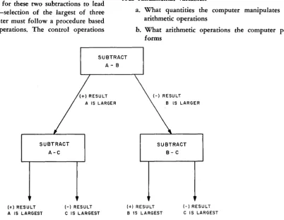
To accomplish the typical data-prQcessing task just discussed, a cQmputer WQuld perfQrm two subtractiQns in sequence. In order fQr these two subtractiQns to' lead to the desired result-selectiQn Qf the largest Qf three quantities-the computer must fQllow a prQcedure based Qn certain cQntrol Qperations. The contrQl QperatiQns are as follows:
a. Selecting any two Qf the quantities for the first subtraction.
b. Determining from the result Qf the first sub-traction which of the twO' quantities is the larger.
c. Selecting the correct quantities fQr the secQnd subtraction.
d. Determining from the result of the second sub-traction which quantity is the largest of the three.
All such cQntrQI QperatiQns are based Qn specific rules. Thus, in the preceding example, the computer selects the larger Qf two numbers, A and B, according to this rule: If subtracting A frQm B results in a plus quantity, select B; if the result is minus, select A. After selecting the larger number according to this rule, the computer fQllows a second rule to' decide what quantities it should Qperate on for the second subtraction: If A is larger than B, subtract A frQm C; if B is larger than A, sub-tract B frQm C. From the plus or minus result Qf this operatiQn, the final answer is Qbtained.
In the example, the cQntrQl operations determine which quantities the computer operates Qn in perform-ing the twO' subtractiQns and, also, what the cQmputer does with the results Qf each subtraction. The example shows a typical cQmbinatiQn of control and arithmetic Qperations in the processing of data. In general, CQn-trQI operatiQns in computer data prQcessing determine fQur fundamental variables:
a. What quantities the computer manipulates by arithmetic Qperations
b. What arithmetic QperatiQns the cQmputer per-forms
SUBTRACT A-B
(t) RESULT
SUBTRACT A-C
(-) RESULT
A IS LARGEST C IS LARGEST
(+) RESULT
SUBTRACT B-C
(-) RESULT
B IS LARGEST C IS LARGEST
Figure J-2. Data Processing - Finding the Largest of Three Numbers, A, 8, and C
[image:26.617.120.523.410.721.2]PART 1 CH 2
UNCLASSIFIED
T.O.
31P2-2FSQ7-2Need for High-Speed Computers 2.1.3-2.3.3
c. What sequence the computer follows in per-forming the arithmetic operations
d. What the computer does with the results of each arithmetic operation
Control operations are sometimes called logical oper-ations because they select and arrange the steps in a given task of data processing in strict accord with logical rules for the task.
2.2 THE NEED FOR HIGH-SPEED COMPUTERS
2.2.1 General
If data-processing tasks were confined to simple problems such as the one discussed in the preceding section, there would be no need for complex, high-speed computers. In a small office, for example, where the only data-processing tasks are simple bookkeeping procedures, small, hand-operated computing machines (e.g., adding machines) are sufficient. The case is dif-ferent when enormous quantities of data must be con-tinually processed with extreme speed and accuracy. In such a case, it becomes practical to use a data-processing machine in place of a group of men working with pencil and paper or with small, hand-operated calculat-ing machines.
2.2.2 Air Defense Needs
In the present-day air-defense system of the United States, huge quantities of data must be continually searched out and accurately processed at high speed. For example, when a strange aircraft is detected by radar, it must be identified as friendly or hostile. To accomplish this, the flight plans of all commercial air-lines and friendly aircraft must be searched out and compared with the movement of the detected aircraft. At the same time, data must be calculated to determine precisely when and how the aircraft (or missile) is to be intercepted if it is found to be hostile. Naturally, if
all these calculations are to be useful, they must be completed before the aircraft disappears. As the speed of aircraft increases far beyond 1000 miles per hour (mph), it becomes impractical for aircraft id.entifica-tion and intercepid.entifica-tion to depend on a group of men who thumb through flight plans, ballistic tables, etc. It is absolutely necessary, therefore, to have a high-speed device that can accept, store, and process very large quantities of d.ata rapidly and accurately and de-liver the correct output information. Only such a high-speed device can provide correlated data quickly enough for use in making the correct tactical decisions neces-sary for air defense.
The large high-speed, electronic computing chines of today are well suited to this task. Such ma-chines can multiply 6-digit numbers at speeds as high as 60,000 multiplications per second, with only one error in every 10 billion operations. Furthermore,
digi-tal computers can store large quantities of data and can locate and process needed items in a fraction of a second.
2.3 BASIC CLASSES OF COMPUTING MACHINES
2.3.1 Basis of Classification
Computers are classified, according to their basic principles of operation, as digital or analog.
2.3.2 Digital Computers
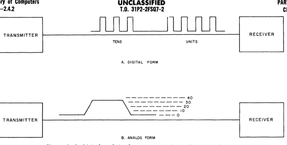
A digital computer is a computing machine that processes data expressed as digits or numbers, and man-ipulates the data by means of arithmetic or logical con-trol operations in a predetermined manner, and gener-ally delivers the resulting information in the form of digits. For instance, the number 34 might be represented in a digital computer as 3+4 pulses on a line as in A, figure 1-3.
A digital computer operates on data in much the same way that a man would manipulate the data in carrying out arithmetic computations with pencil and paper. Similar to a man making an arithmetic computa-tion, a digital computer manipulates digits in a se-quence of distinct steps determined by certain mathe-matical rules.
The digits used to represent items of data or speci-fic instructions for processing the data must belong to a particular number system (such as the familiar decimal system) chosen for the computer model being used. Similarly, the results of operations by a digital com-puter are usually delivered in the form of numbers.
Since a digital computer operates on data in a series of distinct steps, there is necessarily some delay between the start and the completion of each operation. Furthermore, if a series of arithmetic operations are to be performed, each operation must be completed in turn before the next is begun. Nevertheless, the use of electronic and magnetic elements in digital computers permits these machines to perform thousands of oper-ations in an extremely short time-some operoper-ations re-quire only a few microseconds (usec).
In summary then, digital computers have the fol-lowing basic characteristics:
a. All data handled by the computer must be in the form of digits of a particular number system. b. The computer processes data by performing
pre-determined arithmetic and logical control oations on the digits. These operoations al'e per-formed in discrete steps, much as arithmetic operations are performed with pencil and paper.
2.3.3 Analog Computers
An analog computer, unlike a digital computer, is a computing machine in which data are converted, for purposes of computation, not into digits but into physi-cally measurable quantities such as lengths, voltages, or
History of Computers
2.3.3-2.4.2
UNCLASSIFIED
T.O. 31P2-2FSQ7-2
PART 1 CH 2
I...-.-.----JIUUUL
TRANSM ITTER RECEIVER
TENS UNITS
A. DIGITAL FORM
- - - 40
/
, . . . - - - . . \ - - - 30
- - - 20
- - - 10
_ _ _ - . . I
1..--- - - -
0TRANSMITTER RECEIVER
B. ANALOG FORM
Figure 1-3. Digital and Analog Representations of the Number 34
angles (as shown in B, fig. 1-3). Computed results are obtained by the action of moving parts or electrical signals. These actions or signals do not represent digits. Rather, they are related to one another in such a way as to represent the relationships among the terms of a mathematical equation. They also interact with one an-other in such a way as to represent the mathematical operations indicated in the equation.
In other words, an analog computer solves prob-lems by causing physical quantities to vary in a manner analogous to the way in which the variables in a prob-lem change. For example, if distance equals velocity multiplied by time, a moto'! running at a speed propor-tional to velocity during a given time interval will turn a gear train through an angle proportional to distance. Thus, a continuous solution of distance in the equation: Distance = Velocity x Time, may be obtained. Action of this kind is typical of the manner in which analog computers solve problems. A fundamental characteris-tic of analog computers is that they provide continuous solutions to a given problem.
2.3.4 Physical Size of Components
The physical size of a computing machine is deter-mined to a great degree by the job which it is to do. Hence, a simple calculator that is hand-operated and used only to add or subtract groups of numbers may be quite small. However, a data-processing machine such as the AN/FSQ-7, which must automatically store and process enormous quantities of data, is very large. An AN/FSQ-7 fills a building several stories high (see' fig. 1-1).
2.4 HISTORY OF COMPUTERS 2.4.1 Early Computing Machines
The first counting aids used by man probably con-sisted of fingers, pebbles, or other similar items. One of
the earliest "machines" is the abacus, which evolved from the use of pebbles. This device, shown in figure 1-4, is one of the simplest forms of an adding or counting machine. It consists of a series of rods on which the positioning of beads records the numbers 0
through 9. Addition or subtraction can be accomplished on each bar individually. However, the carrying of the
1 when a sum is greater than 9 cannot be done auto-matically.
The first machine that made provisions for auto-matic carrying of digits when the sum of a column is greater than 9 was the Pascal machine, invented in 1642. This has been termed the first authentic account-ing machine and it was used to figure English currency. The machine was basically a hand-operated, gear-driven counter. Addition was accomplished by turning input wheels a distance equal to the money to be added. This is similar to the addition of mileage on an odometer. The basic forerunner of the modern large-scale computers was the Babbage Analytical Engine, con-ceived by Charles Babbage in 1833. This machine, which operated somewhat similarly to a device called the Ja-quard Loom, made use of cards and strips of metal with various holes punched in them to record numbers. A number was represented by an equivalent number of holes. After the Babbage machine, several improved types of computing machines were developed. Notable among them was the Hollerith machine, which used the Jacquard idea of holes punched in tape or cards. How-ever, in the Hollerith machine these holes controlled electrical mechanisms.
2.4.2 Advent of Large, High-Speed Computers
The first of -the large-scale, high-speed computing machines was the Mark I, completed in 1944 by Harvard University and International Business Machines. This
[image:28.617.48.523.31.271.2]PART 1 CH 2
UNCLASSIFIED
T.O.
31P2-2FSQ7-2Fig. 1-4
Figure 1-4. The Abacus - The Number Represented by the Position of the Beads is 34
machine uses the IBM punched-card method to insert the input data. Its output is typed out by an electric typewriter. The sequence of operations of the Mark I is controlled automatically. The machine can add, sub-tract, multiply, divide, or perform other related arith-metic operations. It is primarily a relay-operated device.
The Harvard Mark I was highly successful, but relay operation was undesirably slow. The first all-electronic digital computer was the ENIAC, built by the University of Pennsylvania in 1946. This used 18,000 vacuum tubes and could add two 10-digit decimal num-bers in 200 microseconds, or multiply them together in 2 to 3 milliseconds.
Most of the refinements in recent years, as exem-plified by the IBM model 700 series (the first mass-produced digital computers) and the AN/FSQ-7, have been concerned with increasing the amount of informa-tion which can be stored in the machines and increasing the speed at which the machines operate. The relative slowness of relays, which are used in the Mark I (and Mark II), cannot be tolerated when processing data for the air-defense system. It is necessary to use special high-speed electronic circuits, which operate very much faster than relays. In addition, it is necessary to use special methods of data storage, that permit extremely high-speed insertion and extraction of data.
[image:29.613.82.585.60.322.2]Blank Page
8
UNCLASSIFIED T.O. 31P2-2FSQ7-2
UNCLASSIFIED
PART 1
CH 3
UNCLASSIFIED
T.O. 31P2-2FSQ7-2Digital Computers
3.1-3.2.1.1
CHAPTER 3
ELEMENTS AND COMPONENTS REQUIRED BY DIGITAL COMPUTERS
3.1 THE LANGUAGE USED BY DIGITAL COMPUTERS
The task of a digital computer is to process data, expressed in the form of digits, by performing certain predetermined arithmetic and control operations on the data. These operations are predetermined by a set of instructions called the pro gram, which has been pre-viously made up by the operator.
In some computers, the instructions may be in the form of special wiring (i.e., of control circuits of the machine). Such a computer would use a control panel somewhat similar to a telephone switchboard to direct operations. This is called a control panel program. In stored program computers, however, the instructions are expressed in the form of digits. That is, each in-struction is identified by a code number. The program, a list of code numbers, is fed to and stored in the computer in a manner similar to the input and storage of data. Then, by a process of decoding, the computer can direct itself in the solution of the problem for which the program was written.
A computer does not "understand" digits from a numerical point of view. It merely responds to speci-fic physical conditions created in the components of the computer. These physical conditions-voltages, cur-rents, etc., represent the digits. The physical conditions interact to produce a set of conditions that represent digits expressing the solution to a problem. Thus, the "language" used by computers consists ultimately of specific physical conditions in its components. Conse-quently, all data and instructions fed to a computer must be represented by specific physical conditions in the computer. For example, if the digits 0, 1, 2, 3, and 4 are to be presented to a digital computer, they must be presented as five separate physical conditions that can be set up in the components of the computer.
One type of physical condition that can represent a digit is a voltage on a voltage input line. To present five different digits to a computer, therefore, five dif-ferent voltage input lines could be used. Similarly, volt-ages on output lines, obtained by processing the input data, could represent the digits in a desired manner. Then, if a voltage were applied to the line representing the digit 1 and another voltage were applied to the line representing the digit 2, along with the order to add the two digits, the response of the computer would be a voltage on the output line that corresponds to the
digit obtained by adding 1 and 2; this would be the output line representing the digit 3.
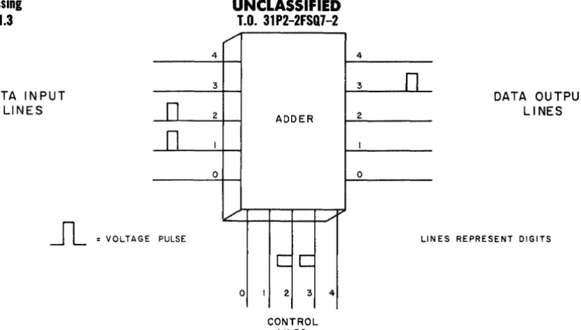
The order for the computer to add the input digits -or any other order that the computer can carry out -would also be presented to it in the form of groups of digits. Digits representing instructions to the com-puter for operating on input data could be fed into a special set of control lines reserved for instructions only. With such an arrangement, the digits represent-ing data and the digits representrepresent-ing orders would not be confused by the computer. If the order "add" were assigned the digit group 23, this order could be pre-sented to the computer by voltages on the control lines representing digit 2 and the digit 3. Figure 1-5 illus-trates how such an arrangement would lead to addition of the digits 1 and 2.
The preceding description is extremely simplified and not necessarily based on any system in common use. It does illustrate, however, the type of "language" that a digital computer "understands." Figure 1-5 gives an idea of the fundamental nature of information rep-resentation in a digital computer. To represent a 3, the 3-line must have a pulse on it; if no 3 is present, no pulse is present on the 3 line. In other words, an on or off condition represents the presence or absence of a digit, respectively.
The decimal system of numbers can be represented this way, but a far simpler number system, made up entirely of the digits 0 and 1, can be more easily used. This binary number system can represent any number by a series of l's and O's. For instance, a binary number equivalent to decimal 25 is 11001 (see Part 2). Because binary numbers can be used to represent any quantity, they can be used in digital computers. A 1 can be repre-sented by the energized condition of a relay and 0 by the de-energized relay condition.
3.2 DIGITAL-COMPUTER ELEMENTS 3.2.1 Data Processing
3.2.1.1 General
Should we wish to know a single number that is equal to 24 times 512, we would multiply the two num-bers together, thus:
24 x 512 = 12,288
Both sides of the equation are equal-we did. not gain any information by multiplying (processing)
Data Processing
3.2.1.1-3.2.1.3
UNCLASSIFIED
T.O. 31P2-2FSQ7-2
PART 1 CH 3
DATA INPUT LINES
4
3
,/"
4
3
n
n
2 ADDER 2DATA OUTPUT LINES
n
I I0 0
V . /
~
= VOLTAGE PULSE LI NES REPRESENT DIGITSc:
C
0 I 2 3 4
CONTROL
[image:32.617.75.493.33.271.2]LINES
Figure J -5. Numbers and Control Instructions Represented in the Form of Voltages
the data, although it is admittedly in a form more suit-able for such purposes as comparison with other num-bers, adding to other numnum-bers, etc. It should always be kept in mind that data processing machines generate, no new information even though their processing re-sults in much greater usability of the existing data. It should also be remembered that the operator or
pro-grammer instructs the machine to perform every
re-quired step. The machine does not think-all of its op-erations and decisions must be built or programed into it by human effort.
3.2.1.2 Examples of Simple Data Processing
A man who processes data does so by following an exact set of rules, although he may not always be conscious of the fact. In making up a payroll, for ex-ample, a paymaster performs a series of predetermined operations which may be written down in a check-list which he must follow. The operations governed by the check-list and their sequence may be as follows:
1. Receive and store (write down) necessary data such as:
a. Number of hours worked by each employee b. Pay rates for each employee
c. Deductions from gross pay for each employee
2. On data stored for each employee, perform arithmetic operations such as:
a. Multiply hours by hourly pay rate, write down partial products, and add partial prod-ucts for complete product
b. Multiply the sum obtained in operation a by a tax rate
c. Subtract the product obtained in operation b from the product obtained in operation a
3. Make available, in a useful form, the results ( output) of the preceding operations (1 and 2).
Throughout the task of making up a payroll, an efficient paymaster would perform only those operations required by the rules of the task. He would not, for example, add up the ages of all the employees, even if this data appeared on the original documents re-ceived. On the other hand, the paymaster would oper-ate on all the data necessary for the task, and he would perform all necessary operations, as determined by the rules of the task.
Hence, to perform his work properly a paymaster must have some means of storing the required data and the appropriate instructions (such as paper, charts, tables, etc.). Morever, he must be able to extract data as needed and perform arithmetic operations in proper sequence. Finally, he must have means of making avail-able in useful form the results of the operations-for example, a means of making out pay checks.
3.2.1.3 Machine Requirement for Data Processing
If the paymaster were making out the payroll on a computing machine, the machine would require facil-ities for:
a. Receiving necessary data
b. Storing the data
c. Controlling, by the rules of the task, the selec-tion of data to be operated on and the proper sequence of operations
d. Performing required arithmetic operations
e. Making available in useful form the results of the operations
PART 1
CH 3
UNCLASSIFIED
T.O. 31 P2-2FSQ7-2
Input Element 3.2.1.3-3.2.4
In other words, the computer would need an input ele-ment, a storage eleele-ment, a control eleele-ment, an arith-metic element, and an output element.
The operational elements listed above are the ele-ments required by typical digital computers. The follow-ing paragraphs describe these elements and explain the tasks performed by each. Notice the similarity between corresponding computer operations and human oper-ations, and remember that all steps originate with the human operator (programmer).
3.2.2 Input Element
The first operation that a digital computer must perform in a data-processing task is to accept the data pertinent to the task, and the instructions (program) for performing it. As explained in section 3.1, all data and instructions must be presented to a stored program computer in the form of digits, and these digits must be such that they can be represented by physical condi-tions in the computer components.
If each computer component has only two possible conditions-e.g., the open and the closed positions of a relay-all data must be presented as combinations of only two digits-e.g., 0 and l.
Obviously, there must be an element that can ac-cept the digits as they are presented by the operator, and this element should set up representative physical conditions in the computer. This input unit is called the input element: it provides one-way communication from the outside world to the computer. Data and in-structions are fed to a computer through an input ele-ment; but an input element returns nothing to the out-side world.
Items of data presented to the input element are not necessarily in the exact form that the rest of the computer elements can use. For example, in figure 1-6, a typewriter input might be used with which the oper-ator would type out the data and instructions in a decimal code. The typewriter would have switches con-nected to each key which would convert the hitting of a key into an electrical impulse. The electrical impulse