Modeling, Static and Dynamic Analysis of Marine Propeller
Blade by Using Composite Material
K.Sai Surya Teja
1(M.Tech Scholar)
&
Dr.K.Lalit Narayana
2(Professor)
Department of Machine Design1sir C.R.REDDY college of engineering & technology, vatluru, Andhra pradesh, 521201, INDIA
[email protected]2
ABSTRACT
Propeller is subjected to an external hydrostatic
pressure on either side of the blades depending on
the operating depth and flow around the propeller
also result in differential hydrodynamic pressure
between face and back surfaces of blades. The
propeller blade is modeled such that it can with stand
the static load distribution and finding the stresses
and deflections for STAINLESS STEEL ,CFRP and
GFRP materials. CFRP and GFRP composites are
finding wide spread use in naval applications in
recent times. Ships and under water vehicles like
torpedoes Submarines etc. Torpedoes which are
designed for moderate and deeper depths require
minimization of structural weight for increasing
payload, performance/speed and operating range for
that purpose composite materials are casting is used
for the fabrication of propeller blades. In current
years the increased need for the light weight
structural element with acoustic insulation, has led to
use of composite propeller. The present work carries
out the structural analysis and dynamic to
STAINLESS STEEL, CFRP and GFRP propeller
blade which proposed to replace the propeller blade
to find the better results.
This work basically deals with the modeling and
design analysis of the propeller blade of a torpedo
for its strength. A propeller is complex 3D model
geometry. This requires high end modeling CATIA
software is used for generating the blade model. This
report consists of brief details about composite
materials and the advantages of using composite
propeller over the conventional metallic propeller.
By using ANSYS software modal analysis and static
structural analysis were carried out for STAINLESS
STEEL, CFRP and GFRP (composite material).
Key words: catia, cfrp, gfrp, stainless steel, ansys.
INTRODUCTION TO PROPELLER
Marine propeller is a component which forms the
principal part of ships since it gives the required
propulsion. These materials are extensively used in the
manufacturing of various structures including the marine
propeller. The hydrodynamic aspects of the design of
composite marine propellers have attracted attention
because they are important in predicting the deflection
and performance of the propeller blade.
For designing an optimized marine propeller one has to
understand the parameters that influence the
hydro-dynamic behavior. Since propeller is a complex geometry,
the analysis could be done only with the help of numerical
tools. Most marine propellers are made of metal material
such as bronze or steel. The advantages of replacing metal
with an CRPF & GFRP composite are that the latter is
advantage is that the deformation of the composite
propeller can be controlled to improve its performance.
Propellers always rotate at a constant velocity that
maximizes the efficiency of the engine. When the ship
sails at the designed speed, the inflow angle is close to its
pitch angle. When the ship sails at a lower speed, the
inflow angle is smaller. Hence, the pressure on the
propeller increases as the ship speed decreases. The
propulsion efficiency is also low when the inflow angle is
far from the pitch angle. If the pitch angle can be reduced
when the inflow angle is low, then the efficiency of the
propeller can be improved.
II. LITERATURE REVIEW
[1] M. A Ishak, Sulaiman S., Baharudin B. T. H. T.,
and Syajaratunnur Y “RESEARCH ON THE SHIPP
ROPELLER BLADE TO DETERMINECHANGES
IN THE MECHANICAL PROPERTIES BASED ON
THE FORCES PROJECTION”, [2017]
Research that the existing ship propeller and the effects of
casted specimen on the changes of mechanical properties
of the propeller structure. The specimen prepared is
referred to ASTM E8 2008 standard and including two
projections is Longitude and Latitude projected,
according to the forces analysis exerted on blade
structure.
[2] PALLE PRASAD, LANKA BOSU BABU
,“DESIGN AND ANALYSIS OF THE PROPELLER BLADE”,.[2017] They work on the structural analysis of
a CFRP (carbon fiber reinforced plastic) propeller blade
which proposed to replace the Aluminium propeller blade.
Also finding the stresses and deflections for both
aluminium and carbon fiber reinforced plastic materials.
for both aluminium and carbon fiber reinforced plastic
materials and also finding its strength.
[3] A. Satya Dinesh, G. V. Naga Mani, “Modelling
and Analysis of a Shaft Blade for its Strength”, [2016]
They examine the structural analysis of CFRP propeller
blades which in future replaces the aluminium propeller
blade. And this study basically deals with modelling and
design analysis for propeller blade for torpedoes
application.
[4] G.Rajesh ,“Modelling and Analysis of Propeller
Blade with Different Materials Using FEA”, [2016]
They studied the structural analysis of a propeller blade
which proposed to replace the Aluminium propeller blade
for torpedoes application and this work basically deals
with the modelling and design analysis of the propeller
blade of a torpedo for its strength and they findings the
stresses and deflections for both materials.
Types of marine propellers
1. Controllable pitch propeller
2. Skewback propeller
3. Modular propeller
1. Controllable pitch propeller
A controllable pitch propeller One type of
marine propeller is the controllable pitch propeller.
This propeller has several advantages with ships.
These advantages include: the least drag depending
on the speed used, the ability to move the sea vessel
backwards, and the ability to use the "vane"-stance,
which gives the least water resistance when not using
the propeller (e.g. when the sails are used instead).
An advanced type of propeller used on German
Type 212 submarines is called a skewback propeller.
As in the scimitar blades used on some aircraft, the
blade tips of a skewback propeller are swept back
against the direction of rotation. In addition, the
blades are tilted rearward along the longitudinal axis,
giving the propeller an overall cup-shaped
appearance. This design preserves thrust efficiency
while reducing cavitations, and thus makes for a
quiet, stealthy design.
3. Modular propeller
A modular propeller provides more control over the
boats performance. There is no need to change an
entire prop, when there is an opportunity to only
change the pitch or the damaged blades. Being able
to adjust pitch will allow for boaters to have better
performance while in different altitudes, water
sports, and/or cruising
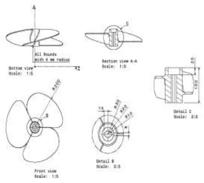
Dimensions of blade figure 1
Dimensions of propeller blade figure 2
MODELING OF PROPELLER BLADE BY USING CATIAV5
Figure 3 blade wing
Figure 4 propeller blade
CALUCULATIONS:
Total Area Of the circle =πR2
= 3.141X302
= 2826.9 mm2
Total Blade Area = π r2 X DAR
= 2826.9X0.92
=2600.748 mm2
(DAR = TBA/TAC = 2600.748/2826.9=92 %)
Relationship between Pitch & Pitch Angle
Formula: Pitch = 2π r X Tan a
Where: a = pitch angle and r = radius andπ=3.14159
Pitch Angle = 120
Pitch = 326.318 mm
Speed = (RPM/Ratio)(Pitch/C)(1-S/100)
Speed = (1000/0.5X326.316/1)(1-0/100)
assume Ratio=1/2,
= 652636X60/106 Gear ratio(C) = 1
=39.1581 km/hr
Slip(S)=0
Boat Speed VB = 24.3317 mile/hr; (1 mile = 1.609344
kilometers)
The thrust (T) is equal to the mass flow rate (.m) times the difference in velocity (V).
T = m x (VB – VA)
Mass Flow Rate per hr (m) = area of blade x speed of the boat
= 2600.74 x 10-6 x39.1581 x 103
= 101.840 m 3 /hr
Thrust (T) = m x (VB – VA) = 101.840 x 39.1581 x 10 3
= 3987860.9 N
= 3.98 MN
Steel Alloys
Alloy steels used in marine propeller construction
have great strength, more so than other fields of
engineering would require. These materials must
withstand the forces that occur on today's modern
marine propeller. These steels contain small
percentages of carbon, nickel, chromium, vanadium,
and molybdenum. High-tensile steels will stand stress
of 50 to 150 tons per square inch without failing.
Such steels are made into tubes, rods, and wires.
steel. Stainless steel resists corrosion and is
particularly valuable for use in or near water
CFRP
Carbon fiber reinforced polymer, carbon fiber reinforced plastic or carbon fiber reinforced thermoplastic (CFRP, CRP, CFRTP or often simply carbon fiber, carbon composite or even carbon), is an extremely strong and light fiber-reinforced plastic which contains carbon fibers. The alternative spelling 'fiber' is common in British Commonwealth countries. CFRPs can be expensive to produce but are commonly used wherever high strength-to-weight ratio and rigidity are required, such as aerospace, automotive, civil engineering, sports goods and an increasing number of other consumer and technical applications.
The binding polymer is often a thermo set resin such as epoxy, but other thermo set or thermoplastic polymers, such as polyester, vinyl ester or nylon, are sometimes used. The composite may
contain aramid (e.g. Kevlar, Twaron), aluminium, ult ra-high-molecular-weight polyethylene (UHMWPE) or glass fibers in addition to carbon fibers. The properties of the final CFRP product can also be affected by the type of additives introduced to the binding matrix (the resin). The most frequent additive is silica, but other additives such as rubber and carbon nano tubes can be used. The material is also referred to as graphite-reinforced polymer or graphite fiber-reinforced polymer (GFRP is less common, as it clashes with glass-(fiber)-reinforced polymer).
GFRP
Glass fiber reinforced polymer rebar is a high value-added construction product. The mega infrastructure providers, such as governments, now have acknowledged the fact that GFRP is a cost-effective construction material that has the full potential to extend the life of public structures where corrosion can have a huge economic and environmental impact. With the rise of corrosion due to global warming, fiberglass reinforcement material has gained considerable popularity. In future, these advanced composite materials would demonstrate their strengths and properties more evidently
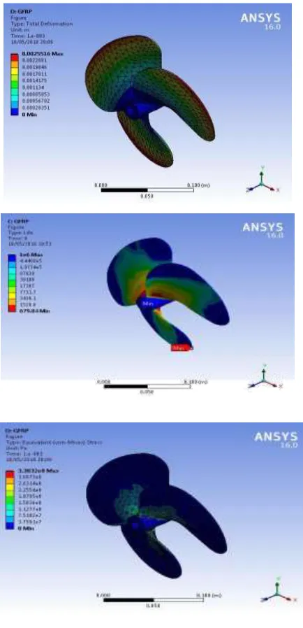
Modal & Static Structural Analysis Of Propeller
Modal & Static Structural Analysis Of Propeller
Blade (CFRP) figure 10 to 13
Modal & Static Structural Analysis Of Propeller
Blade (GFRP) v figure 14 to 17
Comparison of all materials
TABLE 1
RESULT GRAPHS: Stainless
Steel
CFRP GFRP
Von Misses Stress (Pa)
6.6291 x10⁻⁶MPa
6.6988x10
-6MPa
7.0377x10
-6MPa
Maximum Principle Elastic Strain
3.499x10⁻³ 6.6868x10 -3
8.306x10⁻³
Total Deformatio n (m)
3.9111x10 -3
6.3454x10 -3
9.3358x10 -3
Life (s) 1 x10⁶ 1x10⁶ 1x10⁶ fatigue (s) 7.3317x10
5
1.4829x10 6
All loads of materials deformation showed in these
graph
Materials load comparing with the strain
Materials load comparing with stress
Materials load comparing to the life of the materials
Materials load comparing to the fatigue damage of the all materials .
Conclusion
The static analysis and dynamic analysis are carried
out for the different type of materials; those are
Carbon Fibre Reinforced Plastic (CFRP) Glass Fibre
Reinforced Plastic (GFRP) and Stainless Steel. MPa
The vonmises stress acting on the propeller
produced from CFRP is 6.6988x10⁻⁶MPa,
and the total deformation is 6.3454x10⁻³m.
The vonmises stress acting on the propeller
produced from GFRP is 7.0377x10⁻⁶ MPa,
and the total deformation is 9.3358x10⁻³m.
The vonmises stress acting on the propeller
produced from Stainless Steel is 6.6291
0 0.005 0.01
-5000
Total
0D
ef
or
ma
tion
Load
Load vs Total
Deformation
CFRP GFRP Stainless Steel -0.01 0 0.01 -5000 0Eq
u
iv
ale
n
t
Elas
tic
St
rain
LoadLoad vs Equivalent
Elastic Strain
CFRP GFRP 0.00E+00 5.00E+08 1.00E+09 -5000 0M
ax
imu
m
Pr
in
cip
le
St
ress
Load
Load vs Maximum
Principle Stress
CFRP GFRP 0.00E+00 5.00E+05 1.00E+06 1.50E+06 -5000 0Lif
e
Load
Load vs Life
CFRP GFRP Stainless Steel 0.00E+00 5.00E+05 1.00E+06 1.50E+06 -5000 0
D
ama
ge
Load
Load vs Damage
CFRP
GFRP
x10-6 MPa, and the total deformation is
3.9111x10⁻³m.
From the above result the life and the
damage of the propeller blade depends on
the type of the material, in the above case
the life of the material remain same and
whereas the damage of the GFRP is less
when compared with the other materials.
Finally it is concluded that Glass Fibre
Reinforced Plastic (GFRP) material can
give a better performance with respect to
static and dynamic analysis.
REFERENCES
[1]. Properties of engineering materials by RA Higgin
[2]. Engineering material properties and selection by Kenneth G.Budinski
[3]. Mechanics of composite materials by Robert M.Johnes
[4]. An Accurate Four-Quadrant Nonlinear Dynamical Model for Marine...Ralf
[5]. Nonlinear Output Feedback Control of Underwater Vehicle Propellers...Thor I Fossen, Mogens Blanke – 2000 - IEEE JOURNAL OF OCEANIC ENGINEERING
[6]. A.P. Mouritz, E.Gilbert, P. Burchill, K.Challis., “ Review of advanced composites for naval ships and submarines”, Composite structures, 53, pp. 21-41, 2001.
[7]. Abdul M.Khan, Daniel O.Adams, Vinay dayal, Jerald M.Vogel., “Effects of Bend-Twist Coupling on Composite propeller performance”, Mechanics of composite materials and structures, Vol.7, pp.383-401, 2000.
[8]. Ansys 11.0 Documentation guide 4. Ansys 11.0 documentation. 5. Anthony F. Molland , Stephen R. Turnock, Dominic A. Hudson., “ Ship Resistance and Propulsion” , Cambridge university press, 2011.
[9]. Anthony F. Molland , Stephen R. Turnock,. “The Design and Construction of model ship propeller blades in hybrid composite materials”, “Composites Manufacturing” Vol.2, No.1, March 1991.