Design of X/Ku Dual-Band Dual-Linear Polarization Reflectarray
Using Double Parallel Dipole Elements
Fei Xue1, 2, Hongjian Wang1, *, and Min Yi1
Abstract—Two single-layer X/Ku dual-band dual-polarization reflectarray antennas of different sizes with double parallel dipole elements are presented. Elements of the two bands are set to two orthogonal linear polarizations and placed in interlaced grid. The proposed reflectarrays operate in two frequency-bands within X-band centered at 10 GHz and Ku-band centered at 13.58 GHz. The smaller size reflectarray with elements arranged in a 13× 13 grid for X-band and in a 12 ×12 grid for Ku-band is designed and simulated first. Based on the excellent dual-Ku-band performance of the small size reflectarray, then a larger size prototype has been designed, manufactured and measured. Measured results demonstrate the maximum gain of 28.54 dB with 50.93% aperture efficiency at 10 GHz and 31.06 dB with 51.34% aperture efficiency at 13.58 GHz, which show desirable dual-band dual-polarization radiation performance.
1. INTRODUCTION
Parabolic reflectors and arrays are playing an important role in high gain applications. However, both of them have obvious disadvantages. For parabolic reflector, the specifically curved surface makes it difficult to manufacture, in particularly at higher frequencies. It also has difficulties in achieving wide angle beam scanning. The array antenna always requires a complex feed network, which cause high transmission loss and low efficiency of antenna. In order to avoid the above mentioned disadvantages, reflectarray antenna emerged with the advantages of high gain, low profile and mass, low cost, flatness and so on. It is usually an antenna that consists of an illuminating feed antenna and a flat reflecting surface with many microstrip elements [1–3].
Dual-band operation has been a subject of intense interest in microstrip reflectarray design. In the past decades, several techniques have been proposed to achieve dual-band performance of the reflectarray, such as elements printed on a single layer [4–6] or two layers [7–9], or using frequency selective surface (FSS)-backed structures [10–12].
A multiresonance curved double cross element is presented in [4] to achieve dual-band dual linear polarization performance and some simulations have been carried out to confirm the negligible mutual effect between the elements of the two bands. In [5], a single layer element consists of a circular patch with slots and two phase delay lines attached to the patch is utilized to develop dual-band reflectarray operating in X- and K-bands. For the case of two closely separated frequencies, a single layer element consisting of a square ring and patch loaded with slots was suggested in [6]. The required phase shifts in two bands are achieved by varying the size of element and good performance of reflectarray was achieved.
For a two-layer structure, ring with gaps was used as the element to develop a dual-band circularly polarized (CP) reflectarray operating in C- and Ka-bands [7]. In another two-layer configuration, thin
Received 4 April 2016, Accepted 1 July 2016, Scheduled 13 July 2016
* Corresponding author: Hongjian Wang ([email protected]).
1 CAS Key Laboratory of Microwave Remote Sensing, National Space Science Center, Chinese Academy of Sciences, Beijing 100190,
dual-band dual-polarization reflectarray covering two closely separated frequencies [13], which can be used in dual-link satellite communications.
In this paper, two different sizes single-layer dual-band dual-polarization reflectarray antennas operating in X-band centered at 10 GHz and Ku-band centered at 13.58 GHz are presented. Two orthogonal sets of double parallel dipoles, each individually for one band, are used as the cell element. The smaller size reflectarray is composed of 13×13 elements for X-band and 12×12 elements for Ku-band. Simulated results show excellent performances of dual band dual polarization. Then, a larger size reflectarray is designed, manufactured and tested. Only one pyramidal horn antenna is designed as feed of the dual-band reflectarrays for both bands in a fixed position with two orthogonal polarization directions. Measured results show the maximum gain of 28.54 dB at 10 GHz and 31.06 dB at 13.58 GHz and more than 50% efficiency are achieved at both frequency bands.
2. ELEMENT DESIGN AND PHASE CHARACTERISTICS
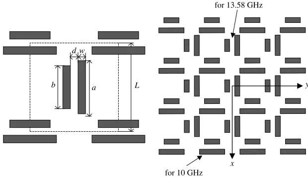
The proposed reflectarrays are composed of two orthogonal sets of double parallel dipoles elements which configuration and arrangement are illustrated at Fig. 1. The double parallel dipoles for both bands are interlaced on top of a single-layer substrate with the same periodicity of L. The periodicity L is set to 14 mm, which equals 0.47 wavelengths at 10 GHz and 0.63 wavelengths at 13.58 GHz. The substrate is F4B laminates with relative permittivity of 2.25 and thickness ofh = 1.5 mm. The length
of the short dipole b is proportional to the length of long dipole a with ratio k (i.e., b =k×a). The gap between the two dipoles is dand the widths of the two dipoles are bothw.
For analyzing the reflection phase characteristics of the element, simulations are analyzed using HFSS, and master-slave boundaries with Floquet port are used to model periodic structures. Figs. 2–4
for 10 GHz
x
y
for 13.58 GHz
b a
d w
L
(a) (b)
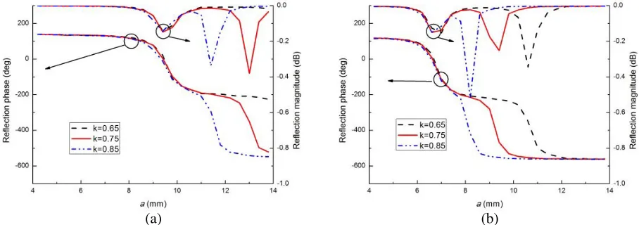
Figure 2. Reflection phase and magnitude against afor different values ofd. (w= 1.5 mm, k= 0.75). (a) 10 GHz. (b) 13.58 GHz.
(a) (b)
Figure 3. Reflection phase and magnitude against afor different values ofw. (d= 1.4 mm, k= 0.75). (a) 10 GHz. (b) 13.58 GHz.
(a) (b)
(a) (b)
Figure 5. Reflection phase and magnitude at different oblique incidence angles. (a) 10 GHz. (b) 13.58 GHz.
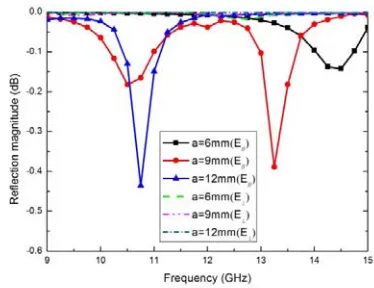
Figure 6. Reflection phase and magnitude against a at X- and Ku-band for different frequencies.
Figure 7. Reflection magnitude against fre-quency for both polarization.
show the influence of element parameters on reflection phase and magnitude curves at the two bands. It can be concluded that the best values of these parameters to have desired reflection phase and magnitude curves at the two bands are as follows: d= 1.4 mm, w= 1.5 mm, k= 0.75. The reflection phase and magnitude at different oblique incidence angles are depicted in Fig. 5. It can be concluded that incidence angles have little influence on reflection phase and magnitude. Fig. 6 shows the phase and magnitude response of the element for different frequencies at X- and Ku-band. It can be concluded that by varying the length of long dipoleafrom 4.2 to 13.8 mm, 650◦ reflection phase range at 10 GHz and 680◦ reflection phase range at 13.58 GHz are obtained, which are much more than the minimum required range of 360◦.
Figure 7 shows the reflection magnitude against frequency for both polarizations. E// represents the polarization of the incident wave parallel to the length direction of the double parallel dipoles, and E⊥ represents the polarization of the incident wave perpendicular to the double parallel dipoles. It can
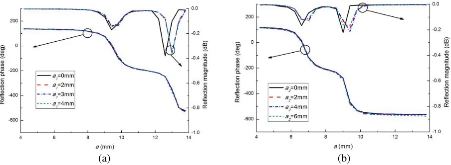
Figure 8. Reflection phase and magnitude against aat 10 GHz when the polarization of the incident wave is set perpendicular to the length direction.
Ku-band dipoles
x y
a1 a2
X-band dipoles Ku-band dipoles X-band dipoles
Figure 9. The unit cell used for analyzing the coupling between the elements of the two bands. (a) The effect of Ku-band dipoles on X-band dipoles. (b) The effect of X-band dipoles on Ku-band dipoles.
(a) (b)
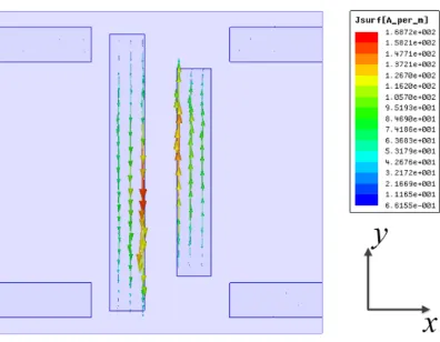
Figure 11. Current distribution on the element surface at 10 GHz.
(a) (b)
Figure 12. Cross-polarized reflection magnitude of the dipoles. (a) 10 GHz. (b) 13.58 GHz.
polarization of the incident wave perpendicular to the length direction of the double parallel dipoles. Similar results can be also achieved at 13.58 GHz, which mean low coupling levels for the double parallel dipoles between the two orthogonal directions.
3. REFLECTARRAY DESIGN AND PERFORMANCE
With the double parallel dipoles mentioned in Section 2, two different sizes single-layer band dual-polarization prime focus reflectarray antennas are designed. The double parallel dipoles for both bands are interlaced on top of substrate with the same periodicity ofL= 14 mm. By varyingafrom 8.4 mm to 12.3 mm for X-band and 5.8 mm to 8.25 mm for Ku-band, required phase shift can be satisfied at the two bands. The smaller size reflectarray with elements arranged in a 13×13 grid for X-band (centered at 10 GHz) and in a 12×12 grid for Ku-band (centered at 13.58 GHz) is printed on a 1.5-mm F4B substrate
(εr= 2.25). The geometry of the small reflectarray is shown in Fig. 13. The X-band of the reflectarray is designed to work in they-polarization and the Ku-band is designed to work inx-polarization.
The focal distances F (distance between the reflectarray and the feed) of the two bands are set to the same value of 134.4 mm. Fig. 14 shows the simulated radiation patterns of the small reflectarray at 10 GHz and 13.58 GHz. As shown in Fig. 14, the side lobe levels are −16.3 dB in E-plane and −18 dB inH-plane with regard to the peak gain at 10 GHz. The side lobe levels at 13.58 GHz are −17.4 dB in E-plane and−17.1 dB inH-plane with regard to the peak gain. The simulated results show a excellent performance of dual band dual polarization radiation performance.
Based on the good performance of the small size reflectarray, a larger size reflectarray with elements arranged in a 25×25 grid for X-band (centered at 10 GHz) and in a 24×24 grid for Ku-band (centered at 13.58 GHz) is designed, manufactured and tested. Fig. 15 shows a prototype of the reflectarray. The larger size reflectarray is octagon with aperture size D of 350 mm. The focal distances of the large
Figure 13. The geometry of the small reflectarray.
(a) (b)
Figure 15. Prototypes of the large reflectarray. Figure 16. Simulated radiation patterns of the feed horn.
(a) (b)
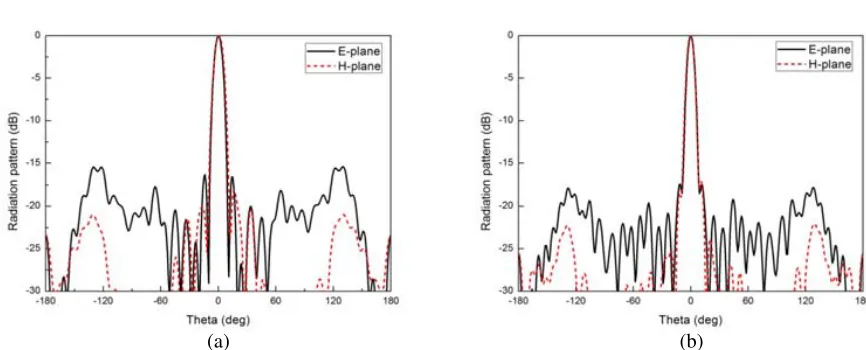
Figure 17. Measured radiation patterns of the large reflectarray. (a) 10 GHz. (b) 13.58 GHz.
reflectarray at the two bands are set to the same value of 268.8 mm. TheF/Dratio is 0.768 at X-band and 0.8 at Ku-band. Only one broadband pyramidal horn antenna is designed as feed of the reflectarray for both bands in a fixed position with two orthogonal polarization directions. The simulated radiation patterns of the feed pyramidal horn antenna at 10 GHz and 13.58 GHz are shown in Fig. 16.
The measured radiation patterns of the large reflectarray for 10 GHz and 13.58 GHz are shown in Fig. 17. The measured peak gain is 28.54 dB at 10 GHz with the sidelobe levels of −25 dB in E-plane and−22 dB inH-plane. The maximum cross-polarization levels is−26 dB inE-plane and−22 dB inH -plane. At 13.58 GHz, the measured peak gain is 31.06 dB with the sidelobe levels of−20 dB in E-plane and −22 dB in H-plane. The maximum cross-polarization levels is −26 dB in E-plane and −25.5 dB in H-plane. The measured aperture efficiency ε is calculated using ε = Gm/Dideal, Dideal = 4πA/λ20
whereGm is the measured gain,Dideal is the ideal directivity, A is the aperture area of the reflectarray.
After calculating, theDidealis 31.47 dB at 10 GHz and 33.95 dB at 13.58 GHz. The NSI planar near-field
(a) (b)
Figure 18. Measured gain and efficiency of the large reflectarray versus frequency. (a) X-band. (b) Ku-band.
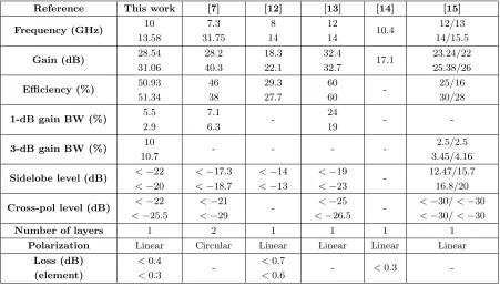
Table 1. Comparison of the proposed reflectarray performance with previous works.
Reference This work [7] [12] [13] [14] [15]
Frequency (GHz) 10
13.58 7.3 31.75 8 14 12 14 10.4 12/13 14/15.5
Gain (dB) 28.54
31.06 28.2 40.3 18.3 22.1 32.4 32.7 17.1 23.24/22 25.38/26
Efficiency (%) 50.93
51.34 46 38 29.3 27.7 60 60 -25/16 30/28
1-dB gain BW (%) 5.5
2.9
7.1
6.3
-24
19 -
-3-dB gain BW (%) 10
10.7 - - -
-2.5/2.5 3.45/4.16
Sidelobe level (dB) <−22 <−20
<−17.3 <−18.7
<−14 <−13
<−19
<−23
-12.47/15.7 16.8/20
Cross-pol level (dB) <−22 <−25.5
<−21
<−29
-<−25
<−26.5
-<−30/ <−30 <−30/ <−30
Number of layers 1 2 1 1 1 1
Polarization Linear Circular Linear Linear Linear Linear
Loss (dB) (element)
<0.4
<0.3
-<0.7
<0.6 - <0.3
-can be concluded that the 1-dB gain bandwidth of 5.5% for X-band and 2.9% for Ku-band are achieved. The narrow bandwidth performance of the reflectarray could be improved by increasing the thickness of the substrate or inserting an air layer between the substrate and the ground plane. The aperture efficiency of the reflectarray is 50.93% at 10 GHz and 51.34% at 13.58 GHz, which shows high efficiency in both bands.
and Electronics Engineers, 2008.
2. Nayeri, P., F. Yang, and A. Z. Elsherbeni, “Beam-scanning reflectarray antennas: A technical overview and state of the art,”IEEE Antennas and Propagation Magazine, Vol. 57, No. 4, 32–47, 2015.
3. Tsai, F. C. E. and M. E. Bialkowski, “Designing a 161-element Ku-band microstrip reflectarray of variable size patches using an equivalent unit cell waveguide approach,” IEEE Transactions on
Antennas and Propagation, Vol. 51, No. 10, 2953–2962, 2003.
4. Abbosh, A. M., “Design of dual-band microstrip reflectarray using single layer multiresonance double cross elements,” Progress In Electromagnetics Research Letters, Vol. 13, 67–74, 2010. 5. Malfajani, R. S. and Z. Atlasbaf, “Design and implementation of a dual-band single layer
reflectarray in X and K bands,”IEEE Transactions on Antennas and Propagation, Vol. 62, No. 8, 4425–4431, 2014.
6. Hamzavi-Zarghani, Z. and Z. Atlasbaf, “A new broadband single-layer dual-band reflectarray antenna in X- and Ku-bands,” IEEE Antennas and Wireless Propagation Letters, Vol. 14, 602– 605, 2015.
7. Han, C., C. Rodenbeck, J. Huang, and K. Chang, “A C/Ka dual frequency dual Layer circularly polarized reflectarray antenna with microstrip ring elements,”IEEE Transactions on Antennas and
Propagation, Vol. 52, No. 11, 2871–2876, 2004.
8. Han, C., J. Huang, and K. Chang, “A high efficiency offset-fed X/Ka-dual-band reflectarray using thin membranes,” IEEE Transactions on Antennas and Propagation, Vol. 53, No. 9, 2792–2798, 2005.
9. Zawadzki, M. and J. Huang, “A dual-band reflectarray for X- and Ka-bands,”PIERS Proceedings, Honolulu, Hawaii, Oct. 13–16, 2003.
10. Smith, T., U. Gothelf, O. S. Kim, and O. Breinbjerg, “An FSS-backed 20/30 GHz circularly polarized reflectarray for a shared aperture L- and Ka-band satellite communication antenna,”
IEEE Transactions on Antennas and Propagation, Vol. 62, No. 2, 661–668, 2014.
11. Chaharmir, M. R., J. Shaker, and H. Legay, “Dual-band Ka/X reflectarray with broadband loop elements,” IET Microwaves, Antennas& Propagation, Vol. 4, No. 2, 225–231, 2010.
12. Chen, Y., L. Chen, H. Wang, X. T. Gu, and X. W. Shi, “Dual-band crossed-dipole reflectarray with dual-band frequency selective surface,” IEEE Antennas and Wireless Propagation Letters, Vol. 12, 1157–1160, 2013.
13. Chaharmir, M. R., J. Shaker, and N. Gagnon, “Broadband dual-band linear orthogonal polarisation reflectarray,” Electronics Letters, Vol. 45, No. 1, 13–14, 2009.
14. Carrasco, E., M. Barba, J. A. Encinar, M. Arrebola, F. Rossi, and A. Freni, “Design, manufacture and test of a low-cost shaped-beam reflectarray using a single layer of varying-sized printed dipoles,”
IEEE Transactions on Antennas and Propagation, Vol. 61, No. 6, 3077–3085, 2013.
15. Hasani, H., C. Peixeiro, A. K. Skrivervik, and J. P. Carrier, “Single-layer quad-band printed reflectarray antenna with dual linear polarization,” IEEE Transactions on Antennas and