202 | P a g e
RELOCATION ALGORITHM FOR ON DEMAND
POSITIONING OF SENSORS IN WIRELESS SENSOR
NETWORKS
V.Hemamalini
1, K.Thamizhmani
2, M.Gayathri
3 ,J.Nivedhidha
41
Research Scholar,Department of Computer Science and Engineering,
Pondicherry Engineering College of Engineering & Technology, Pondicherr (India)
2,3,4
M.Tech Student, Department of Computer Science and Engineering,
Rajiv Gandhi College of Engineering &Technology, Pondicherry (India)
ABSTRACT
The major challenge in designing wireless sensor networks (WSNs) is the support of the functional, such as data latency, and the non-functional, such as data integrity, requirements while coping with the computation, energy and communication constraints. Careful node placement can be a very effective optimization means for achieving the desired design goals. The advances of global positioning systems and communication techniques improve the system in a new and different way. In the new system, users are available for the system on demand,
i.e., users can get on/off any time and any stations. Thus, users apply the system to one-way driving in addition
to round driving. In this paper, we focus on location balances of cars which is a key factor to improve utilization
rate of the system. We propose a relocation algorithm for waiting cars based on virtual spring forces. In the last
of this paper, we report our simulation results and show the effectiveness of our algorithm.
Keywords: Relocation, On Demand, deployment, Traffic, Automation
I. INTRODUCTION
Recent years have witnessed an increased interest in the use of wireless sensor networks (WSNs) in numerous
applications such as forest monitoring, disaster management, space exploration, factory automation, secure
installation, border protection, and battlefield surveillance [1][2]. In these applications, miniaturized sensor
nodes are deployed to operate autonomously in unattended environments. In addition to the ability to probe its
surroundings, each sensor has an onboard radio to be used for sending the collected data to a base-station either
directly or over a multi-hop path. Figure 1 depicts a typical sensor network architecture. For many setups, it is
envisioned that WSNs will consist of hundreds of nodes that operate on small batteries.
A sensor stops working when it runs out of energy and thus a WSN may be structurally damaged if many
sensors exhaust their onboard energy supply. Therefore, WSNs should be carefully managed in order to meet
applications’ requirements while conserving energy. Most of the protocols described above initially compute
the optimal location for the nodes and do not consider moving them once they have been positioned.
203 | P a g e
quality of candidate positions are based on performance metrics like the data rate, sensing range, path
length in terms of the number of hops from a sensor node to the base- station, etc. In addition, the placement
decision is made at the time of network setup and does not consider dynamic changes during the network
operation. For example, traffic patterns can change based on the monitored events, or the load may not be
balanced among the nodes, causing bottlenecks. Also, application- level interest can vary over time, and the
available network resources may change as new nodes join the network, or as older nodes run out of energy.
Therefore, dynamically repositioning the nodes while the network is operational is necessary to further
improve the performance of the network. For instance, when many of the sensors in the vicinity of the
base-station stop functional due to the exhaustion of their batteries, some redundant sensors from other parts of the
monitored region can be identified and relocated to replace the dead sensors in order to improve thenetwork
lifetime. Such dynamic relocation can also be very beneficial in a target tracking application where the
target is mobile. For instance, some of the sensors can be relocated close to the target to increase the fidelity
of the sensor’s data. Moreover, in some applications it may be wise to keep the base-station a safe distance
from harmful targets, e.g., an enemy tank, by relocating it to safer areas in order to ensure its availability.
Relocating the nodes during regular network operation is very challenging. Unlike initial placement, such
relocation is pursued in response to a network- or environment-based stimulus. It thus requires continual
monitoring of the network state and performance as well as analysis of events happening in the vicinity of the
node. In addition, the relocation process needs careful handling since it can potentially cause disruption in data
delivery. The basic issues can be enumerated as follows: when does it make sense for a node to relocate, where
should it go and how will the data be routed while the node is moving? In this section we discuss these issues in
detail and survey published approaches on dynamic node repositioning. We group published work according to
whether the node being repositioned is a sensor or a data collector. In all the techniques covered in this section,
no coordination among relocated nodes is provisioned.
Instead of relocating the nodes at the deployment phase, sensors can be relocated on demand to improve
certain performance metrics such as coverage or network lifetime. This can be decided during the network
operation based on the changes in either application-level needs or the network state. For instance, the
application can be tracking a fast moving target which may require repositioning of some sensor nodes based
on the new location of the target. Furthermore, in some applications there can be an increasing number of
non-functioning nodes in a particular part of the area, necessitating the redistribution of available sensors. In
addition to improving coverage, the energy consumption can be reduced through on- demand relocation of
sensors in order to reach the best efficient topology.
Figure 1(a) Cascaded Movement of Sensors; S3 replaces S2, S2 settles in S1’s position and S1
move to where S0 is.
The approach presented in [3] performs sensor relocation to counter holes in coverage caused by sensors
204 | P a g e
repositioned in the vicinity of the faulty nodes. The selection of the most appropriate choice among multiple
candidate spare nodes is based on the recovery time and overhead imposed. Both criteria would favor
close-by spares over distant ones. Minimizing the recovery time can be particularly crucial for delay sensitive
applications. The overhead can be in the form of energy consumption due to the node’s travel and due to the
message exchange. The latter is especially significant if spares are picked in a distributed manner. In order to
detect the closest redundant sensor with low message complexity, a grid-based approach is proposed. The
region is divided into cells with a designated head for each cell. Each cell-head advertises/requests redundant
nodes for its cell. A quorum-based solution is proposed to detect the intersection of advertisements and
requests within the grid. Once the redundant sensor is located, it is moved to the desired cell without
disrupting the data traffic or affecting the network topology.
Since moving a node over a relatively long distance can drain a significant amount of energy, a cascaded
movement is proposed. The idea is to determine intermediate sensor nodes on the path and replace those
nodes gradually. That is, the redundant sensor will replace the first sensor node on the path. That node also is
now redundant and can move to replace the second sensor node, and so on Coverage improvement is also the
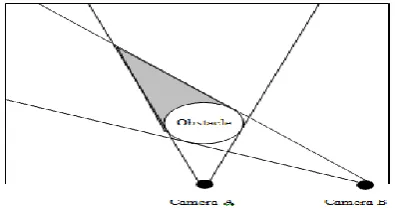
objective of relocating imaging sensors in [7]. Stationary cameras may not provide the desired coverage when
there are environmental peculiarities, e.g., moving obstacles, in the event area as seen in Figure 18. Thus,
moving the cameras in order to avoid obstacles that block their vision would increase the coverage. The
mobility for the camera nodes is made possible through providing a traction mechanism under each camera
that will enable motion in one dimension, as is also implemented in Robomote [6]. This mobility feature on
cameras is actuated when the coverage of the monitored areas falls below a certain ratio. The experiments
performed with real-life target tracking applications have verified that the mobile cameras can increase the
coverage of the monitored area and thus decrease the target miss- ratio significantly when compared to
stationary-node based setups.
Finally, we would like to note that the work of Dasgupta et al. [4], can potentially fit under the category of
dynamic positioning if sensors are relocated after deployment. However, the repositioning is done at the
network planning stage to form the most efficient topology and thus we categorized the scheme as static.
Figure 1(b) An obstacle reduces the coverage of two cameras directed at different areas.
A.RELOCATION ISSUES
(i) When to Consider Relocation The decision for a node movement has to be motivated by either an unacceptable performance measure (despite setting up the most efficient network topology) or a desire to
boost such measures beyond what is achievable at the present node position. Motives vary based on the
205 | P a g e
node coverage in an area, increases in packet latency or excessive energy consumption per delivered packet.
A weighted average may also be pursued to combine multiple metrics based on the application at hand.
Once a node has its motive, it will consider moving to a new position. Such consideration does not necessarily
lead to an actual relocation. The node first needs to qualify the impact of repositioning at the new location on
the network performance and operation. Therefore the “When” and “Where” issues of node movement are very
closely inter-related. In addition, the node must assess the relocation overhead. Such overhead can be incurred
by the node and the network. For example, if the node is a robot, the energy consumed by the mechanical parts
during the movement is a significant overhead to the lifetime of the robot’s battery and thus should be
minimized. Moreover, when energy and timeliness metrics are of utmost concern, the impact on the lifetime of
individual sensors and on route maintenance has to be considered respectively.
Where to Relocate When having a motive to relocate, the node needs to identify a new position that would satisfy the motive, e.g., boost overall network performance. Again, the qualification of the new position and
possibly the search criteria may vary based on the design attributes. Finding an optimal location for the node in
a multi-hop network is a very complex problem. The complexity is mainly resulting from two factors. The first
is the potentially infinite number of possible positions that a node can be moved to. The second factor is the
overhead of keeping track of the network and the node state information for determining the new location. In
addition, for every interim solution considered during the search for an optimal position, a new multi-hop
network topology may need to be established in order to compare that interim solution to the current or
previously picked positions.
A mathematical formulation of the node relocation problem may involve huge numbers of parameters
including the positions of all deployed nodes, their state information (including energy reserve, transmission
range, etc. and the data sources in the network. In addition, a node may need to know the boundaries of the
monitored region, the current coverage ratio of the network, the location of dead sensor nodes or other
information in order to determine its new location. Given the large number of nodes typically involved in
applications of WSNs, the pursuance of exhaustive search will be impractical. In addition, the dynamic nature
of the network makes the node state and sources of data may change rapidly; thus the optimization process
may have to be repeated frequently. Moreover, it may be undesirable to involve the nodes in complex
computation since this diverts both the computation capacity needed for application level processing, e.g., data
fusion, and the energy needed for movement of the node. Therefore, approximate and local solutions, or
search heuristics, are more popular in the context of WSNs [7][13][14].
(ii) Managing and Justifying the Move Once the new location of the node has been picked and confirmed to enhance some desired design attributes, the node should identify a travel path to the new
location. The main contributing factors to the path selection are the total distance to be traveled, the
suitability of the terrain, the path safety and the risk of disrupting the network operation. Minimizing the
travel distance for the nodes is crucial since the energy consumed by the mechanical parts in such a
movement is much more than the communication and computation energy. Therefore, the shortest possible
path should be identified to reach the new location. However, the node also has to pick a path that is
physically feasible to travel over. The node may need to consult a terrain map or rely on special onboard
equipments, e.g., cameras, to avoid obstacles and dead ends. The other concern is protecting the node during
206 | P a g e
events, the node should avoid exposure to harm or getting trapped. For example, the node should not go
through a fire to reach the new location.
The node should also minimize any negative impact on network operation. While the node is on the move, it
must ensure that data continues to flow. For example, a sensor may have to increase its transmission power to
cover the planned travel path in order to make sure that packets will continue to reach it. Continual data delivery
prevents the node from missing important reports during the relocation, which may cause an application level
failure. Such application level robustness is a design attribute in itself. Therefore, it is desirable to restrict
changes to the network topology. Avoiding radical changes to the data routes limits the disruption of ongoing
data traffic, and also curtails the overhead that the relocation introduces. Again, the node performs a trade-off
analysis between the gain achieved by going to a new location and the overheatin terms of additional
energy consumption that the motion imposes on the other nodes. If the motion is justified, the node can
physicallyrelocate.
The last issue is whether there are constraints on the time duration that the node budgets for the move. These
constraints may arise in very dynamic environments in which the traffic pattern changes frequently. In these
cases, the gains achieved by going to a location may be lost or degraded very quickly and the node would find
out that it has to move yet again to a third location or even return to the old position. In the worst case, the node
continues to move back and forth among these locations. Therefore, a gradual approach to the new location may
be advisable in order to prevent this scenario.
II. REPOSITIONING DATA COLLECTORS
As discussed earlier, sensor data is gathered at either the base-station or CHs for aggregation and possibly
additional processing consistent with the computational capabilities of such data collectors (DCs). Dynamic
repositioning of DCs has also been pursued as a means for boosting network performance, dealing with traffic
bottlenecks and preventing interruptions in network operation. Unlike sensor repositioning, the goal for
relocating DCs is usually not local to the individual node and involves numerous network state parameters. In
this section, we focus on approaches that consider a single DC or uncoordinated repositioning of multiple DCs if
more than one exist.
A.Repositioning for Increased Network Longevity
Although energy-aware multi-hop routing does dynamically adapt to changes in sensor energy and traffic
pattern, sensors near a data collector (DC) die quickly as they are the most utilized nodes in the network
[14][15]. Consequently, nodes that are further away from the DC are picked as substitute relays, as depicted
in Figure 19. However, the amount of energy these nodes spend to communicate with the DC is considerably
higher. This effect can spread in a spiral manner, draining the sensors energy and hence shortening the
lifetime of the network. To stop such a pattern of energy depletion, the DC is repositioned[6].
The main idea is to move the DC towards the sources of highest traffic. The traffic density (P) times the
transmission power (ETR) is used as a metric for monitoring the network operation and searching for the best
DC location. The idea is to track changes in the nodes that act as the closest hop to the DC and the traffic
density going through these hops. If the distance between the DC and some of the nodes that are in direct
207 | P a g e
overall network lifetime by considering the number of packets routed through them. If the total P ETR
decreases by more than a certain threshold , the DC will consider relocating to a new position.
Mathematically, the relocation takes place if:
Where ,
SR is the set of sensors that are one hop away from the data collector on active routes,
SRnew is the set of sensors that are one hop away from the data collector at a new location,
Pi is the packet traffic going through node i, measured as the packet count per frame,
E (TRi) is the energy consumed by node i for transmitting a packet to the next hop, and
The summations measure the total energy consumed for packet transmission through all the nodes at theold location and new location of the data collector, respectively.
While such positioning will be ideal for high traffic paths, it can worsen the performance on paths with lower
traffic density or which are topologically opposite to the direction of the DC's motion. Therefore, before
confirming the move, it has been recommended that the DC validates the overall impact on transmission energy
by factoring in the possible extension of some data paths and the cost of signaling overhead to those sensor
nodes affected by the move. In addition, when the DC starts to move, the data gathering process still continues
and thus the routes should be adjusted before the DC gets out of range of some sensors (if any). Unlike the
static approaches discussed in Section 2, route adjustment is an issue in dynamic DC positioning. This issue is
handled in [76] by either increasing the transmission power or designating additional forwarder sensors. The
change in DC position may also introduce shadowing or multi-path fading to some links. Slow or gradual
advance towards the new position is shown to be effective in avoiding unexpected link failures that may cause
negative performance impacts, since it allows the DC to rethink the suitability of the newly-selected position
and/or the decision to move further.
Through simulation, this approach for relocating the DC is shown to not only increase the network longevity
but also to enhance other performance metrics like latency and throughput. First, communication-related energy
consumption and the average energy per packet are reduced as the DC moves closer to the area where more
nodes are collecting data. In addition, nodes collecting the most data are closer to the DC and fewer hops are
involved, lowering the overall latency time for data collection. Moreover, the packet throughput grows since
most messages pass through fewer hops and travel shorter distances, making them less likely to be dropped.
B.Enhancing Timeliness Of Delay-Constrained Traffic
In addition to boosting network longevity, repositioning the DC is useful when real-time traffic with certain
end-to-end delay requirements is involved [7]. For instance, when routes to the DC get congested, most
requests for establishing paths for real-time data may be denied or the deadline miss rate of real-time packets
may increase significantly. Traffic congestion can be caused by an increase in the number of real-time data
packets coming from nodes close to a recent event. In such circumstances, it may be infeasible to meet the
requirements for real-time data delivery. Therefore, repositioning the DC has been recommended in order to
spread the traffic on additional hops and increase the feasibility of meeting the timeliness requirements.
208 | P a g e
desire to increase timeliness even if the miss rate is at a level that is tolerable by the application. To boost
timeliness, the DC is moved to the location of, or close to, the most heavily loaded node [7]. The rationale is
to split the incoming traffic passing through that node without extending the delay experienced by real- time
packets over other routes, as shown in Figure 20. Such loaded nodes are picked based on the real-time traffic
service rate, often determined during route setup in order to allocate bandwidth to both real-time and
non-real-time traffic. Again, the advantages of the relocation have to be qualified to make sure that the overhead
is justified. It is also worth noting that in this approach the impact on link quality is not a major concern
when the DC moves close to a heavily loaded node. This is because it is unlikely that the node is
experiencing a disruptive level of interference while being able to relay a high volume of real-time packets.
As long as the DC remains within the transmission range of all the last-hop nodes, the current routes can be
maintained by only adjusting the transmission power. If the new location places the DC out of the
transmission range of some of the last hop nodes in the current routes, new forwarder nodes that are not
involved in any routing activity are selected. It was argued that those unused nodes introduce very little
queuing delay, which is desirable for on-time delivery of all real-time packets that use these nodes as relays.
We note, however, that designating new forwarder nodes is still more costly than just adjusting the
transmission power. Therefore, if the new location imposes excessive topology changes, alternative positions
which will cause no or minimal topology changes should be considered.
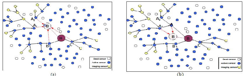
Fig 2. (a) The DC (denoted as B) is relocated to the location of A if the delay is not extended on the path from C to B (b) If real-time traffic through C is affected, B is relocated close to C while still
splitting traffic at A.
C. Maintaining Uninterrupted Operation
Relocating data collectors has also been pursued to keep WSNs operational without interruption. Noting
that some nodes may be isolated (the network may even become partitioned) if one of the DC nodes is
damaged or becomes unreachable to sensors, some of the published schemes repositioned DC nodes in
order to protect them and sustain network connectivity.
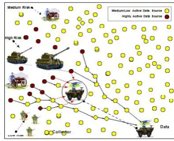
Keeping the DC away from harm is the goal of the GRENN approach proposed in [8]. Two main scenarios
motivate GRENN to reposition a DC. First, the DC may be in the way of an approaching serious event,
such as a fast spreading fire, or a harmful target like an enemy tank. The second scenario may be caused
by a desire to boost network performance by moving the DC node towards the data sources, similar to the
schemes discussed in the previous two subsections. The latter scenario, may actually expose the DC to
209 | P a g e
trade-offs.To access the safety implications of repositioning the DC an evolutionary neural networks based
formulation is pursued. The idea is to track the DC safety levels at different locations and use this
information to define the parameters of the DC safety model. Then the threat implication is estimated as a
function of the proximity to reported events and the severity of those events. If the location of the event is
not accurately known, the data volume related to that event and the location of the reporting sensors are
factored in. An objective function is then formed to balance safety and performance goals and used to guide
the search for the new location of the DC. GRENN has been further extended in [9] to identify a safe route
for the DC to its new position. The same safety assessment model is employed to guide the selection of the
travel path. The effect of the DC's motion on the network performance is also factored in by measuring the
throughput at various spots the DC will visit along the way. The objective function is extended to not only
trade off the safety of the DC and the network performance but also to minimize the travel distance. Shen et
al. [11] have investigated the placement of mobile access points in order to connect nodes in isolated
networks through airborne units or satellites. The deployed nodes usually do not have expensive radios for
long haul communication and usually serve limited geographical areas. The limited communication range
may result in partitioning the network, leaving some nodes unreachable to some others. To overcome such
structural weaknesses in the network, mobile base-stations are employed to interconnect isolated sub-
networks through an airborne relay, such as an unattended air vehicle (UAV) or satellite.
Fig 2.(c) Performance Centric Relocation
III. RELOCATION ALGORITHM
A control center issues relocating requests to location controllers by watching positions of cars with a global
positioning system. A candidate car for relocating is selected on the basis of virtual spring forces. We attach
virtual springs to two places of each vehicle: between the car and other cars and between the car and
borderlines of a service area. At the first setup, the length |vs| of a virtual spring vs is calculated by Equation (9).
Let A(P) be area of a service area P and |Cwait| be the number of waiting cars. The length of springs |vs|
represents an appropriate distance between two waiting cars.
In the former part of the code, movement energies of all waiting cars are calculated, and a car cmax with
maximum energy is selected as a ride-on position for location controller. In the latter part of the code, suppose
that the car cmax moves other stations, a station smin with minimum energy is selected as a drop-off position
fora location controller in the same way. Finally, the relocating request (cmax, smin)is sent to a location
210 | P a g e
A. Psuedo code for relocation algorithm// find car with maximum energy
Cmax = null; Cwait = cars in WAIT |vs| = spring length; WHILE c € Cwait do
EC = energy(c, |vs|,Cwait – C);// calculate movement energy
IF Ec is maximum energy THEN
Cmax = c; END END
//find station with minimum energy Smin = null ; Cwait = Cwait – Cmax;; WHILE s € S do
Es = energy (s, |vs|,S-s);// Calculate movement energy
IF Es is minimum energy THEN Smin = s;
END END
l = location controller closest to cmax;
send (l, cmax,smin);// send relocating request to l
IV.
EXPERIMENTS
A service area of the system is set to a square (800 × 800 pixels). A road network in the area is set to a grid
network (21 × 21), i.e., the length of all road segments is 40 pixels. A pair of ride-on and drop-off nodes is
selected from the nodes randomly. The service process is repeated until the max time 100000t. First, we
report experimental results related to occurrence rate of driving requests. The occurrence rate of driving
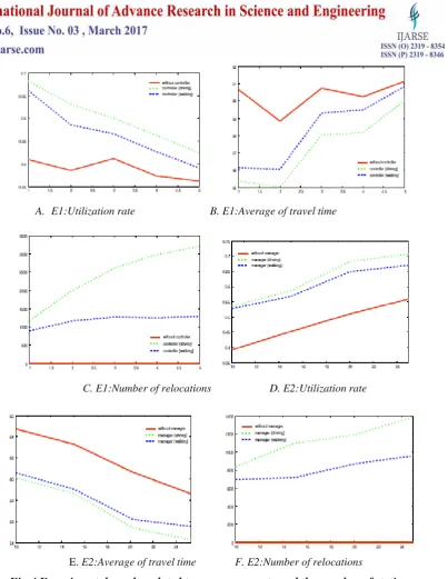
requests is set from 1% to 5%. The number of stations is set to a fixed value 20. Figure 4(a) indicates that
relocating by driving controller can improve from 20% to 40% compared with PT1:without controller.
However, when there are many driving cars occupied by users, the effect is small. Figure 4(b) indicates that
the travel time of users is clearly related to the utilization rate of the system. In other words, high utilization
rate shows convenient access in the service area. Figure 4(c) indicates that the number of relocation strongly
depends on the speed of location controllers. The relocation by walking reaches the limited number about
1000 even in low occurrence rate. On the other hand, relocation by driving reaches the limited number about
3000. Second, we report experimental results related to the number of stations. The number of stations is set
from 10 to 25. The occurrence rate of driving requests is set to a fixed value 1%. Figure 4(d) indicates that a
large number of stations in the service area can satisfy more short-distance driving requests. Figure 4(e)
shows the same tendency in the previous experimental result. Figure 4(f) indicates that a large number of
stations increases the burden on relocation for location controllers. From the experimental results, our
relocation algorithm is effective for on-demand car sharing system. Moreover, improving utilization rate of
211 | P a g e
A. E1:Utilization rate B. E1:Average of travel time
C. E1:Number of relocations D. E2:Utilization rate
E. E2:Average of travel time F. E2:Number of relocations
Fig 4 Experimental results related to occurrence rate and the number of stations.
V. CONCLUSION
Wireless sensor networks (WSNs) have attracted lots of attention in recent years due to their potential in many
applications such as border protection and combat field surveillance. dynamic repositioning of nodes after
deployment or during the normal network operation can be a viable means for boosting the performance. Unlike
the initial careful placement, node repositioning can assist in dealing with dynamic variations in network
resources and the surrounding environment. We have identified the technical issues pertaining to relocating the
nodes; namely when to reposition a node, where to move it and how to manage the network while the node is in
motion. The system provides more convenient access, i.e., users can ride on and drop-off any time and any
stations in a service area. The location balance of cars is a key problem to be solved for improving utilization of
212 | P a g e
the algorithm is estimated by our computer simulation. The results of the simulation show that our algorithm
is effective for on-demand car sharing system. In our future work, we must consider a cooperation among
location controllers and simulate in real city environment.
REFERENCES
[1] I. F. Akyildiz, W. Su, Y. Sankarasubramaniam, E. Cayirci, “Wireless sensor networks: a survey”,
Computer Networks, Vol. 38, pp. 393-422, 2002.
[2] C-Y. Chong and S.P. Kumar, “Sensor networks: Evolution, opportunities, and challenges,” Proceedings
of the IEEE, Vol. 91, No. 8, pp. 1247- 1256, 2003.
[3] K. Akkaya and M. Younis, “A Survey on Routing Protocols for Wireless Sensor Networks,” Elsevier
Journal of Ad Hoc Networks, Vol. 3, No. 3, pp. 325-349, May 2005.
[4] P. Naik and K. M. Sivalingam, “A survey of MAC protocols for sensor networks,” In Wireless Sensor
Networks, C. S. Raghavendra, K. M. Sivalingam, and T. Znati, Eds. Kluwer Academic Publishers,
Norwell, MA, pp. 93-107, 2005.
[5] N. Sadagopan, B. Krishnamachari, and A. Helmy, “Active Query Forwarding in Sensor Networks
(ACQUIRE),” Journal of Ad Hoc Networks, Vol. 3, No. 1, pp.91-113, January 2005.
[6] A. Cerpa and D. Estrin, “ASCENT: Adaptive Self-Configuring Sensor Networks Topologies,”
in the Proceedings of the 21 st
International Annual Joint Conference of the IEEE Computer and
Communications Societies (INFOCOM’02), New York, NY, June 2002.
[7] A. Efrat, S. Har-Peled, J. S. B. Mitchell, “Approximation Algorithms for Two Optimal Location
Problems in Sensor Networks” in the Proceedings of the 3rd International Conference on Broadband
Communications, Networks and Systems (Broadnets’05), Boston, Massachusetts , October 2005.
[8] X. Cheng, DZ Du, L. Wang and B. Xu, “Relay sensor placement in wireless sensor networks,”
ACM/Springer Journal of Wireless Networks (to appear).
[9] S. Poduri, S. Pattem, B. Krishnamachari, and G. S. Sukhatme, “Sensor Network Configuration and the
Curse of Dimensionality,” in the Proceedings of the 3rd IEEE Workshop on Embedded Networked
Sensors, Cambridge, MA, May 2006.
[10] J. Pan, L. Cai, Y. T. Hou, Y. Shi, and S. X. Shen, “Optimal Base-Station Locations in Two-Tiered
Wireless Sensor Networks” IEEE Transactions on Mobile Computing, Vol. 4, No. 5, pp. 458 – 473,
September 2005.
[11] S. S. Dhillon and K. Chakrabarty, “Sensor placement for effective coverage and surveillance in
distributed sensor networks,” in the Proceedings of the IEEE Wireless Communications and Networking
Conference (WCNC’03), New Orleans, LA, March 2003.
[12] T. Clouqueur, V. Phipatanasuphorn, P. Ramanathan and K. K. Saluja, “Sensor deployment strategy for
target detection,” In the Proceedings of the 1st ACM international Workshop on Wireless Sensor
Networks and Applications (WSNA '02), Atlanta, Georgia, September 2002.
[13] K. Akkaya, M. Younis and M. Bangad “Sink Repositioning for Enhanced Performance in Wireless
213 | P a g e
[14] G. Wang, G. Cao, T. La Porta, and W. Zhang, “Sensor Relocation in Mobile Sensor Networks,” in the
Proceedings of the 24th International Annual Joint Conference of the IEEE Computer and
Communications Societies (INFOCOM05), Miami, FL, March 2005.
[15] J. Wu and S. Yang, “SMART: A Scan-based Movement Assisted Sensor Deployment Method in
Wireless Sensor Networks,” in the Proceedings of the 24th International Annual Joint Conference of the