Bio Synthesis Tio
2
Nano Particles Coreshell
Mgo Based Solar Cell
Joseph Sabastin
1, N.Manikandan
2, S.Muruganand
3 1,2,3Department of Electronics and Instrumentation,
Bharathiar University,Coimbatore, (India)
ABSTRACT
The synthesis of metallic nanoparticles is an active area of academic, application research as well and nanotechnology. Different chemical and physical procedures that are currently used for synthesis of metallic nanoparticles present many problems. These problems include generation of hazardous by-products, use of toxic solvents, and high energyconsumption. Biological synthesis of nanoparticles by bacterial, fungi, yeast, and plant extract is the best alternative to develop cost effective, less labor, non-toxic using more green approach, environmentally benign nanoparticles synthesis to avoid adverse effects in many nanomaterials applications. Among the various metal oxide nanoparticles, titanium dioxide nanoparticles have wide applications for dye-sensitized solar cells, in air and water purification, due to their potential oxidation strength, high photo stability and non-toxicity. Till now, titanium dioxide (TiO2) is the cornerstone semiconductors for dye-sensitized (DSSC) nanostructured electrodes for dye-sensitized solar cells. The synthesis of TiO2 nanoparticles, TiO2@MgO core-shell film was obtained by using a simple chemical bath deposition method to coat a thin MgO film around TiO2 nanoparticles. The core-shell configuration was characterized by X-ray diffractometer (XRD), scanning electron microscopy (SEM), Lattice fringes were observed for the TiO2 particles, and the MgO shell showed an amorphous structure, revealing a clear distinction between the core and shell materials. Applying the core-shell film as photoanode to the dye-sensitized solar cells (DSSCs), it shows a superior performance compared to the pure.
Keywords—TiO2@MgO; core-shell; electrode; dye-sensitized solar cell (DSSC).
I.
INTRODUCTION
redox mediator or oxidized dye at the semiconductor surface[5, 6]. The photoinjected electrons are prone to recombination with the oxidized ions or oxidized dye. Coating, although the various table text styles are provided. The formatter will need to create these components, incorporating the applicable criteria that follow.
another semiconductor (e.g., SrTiO3 [7], Al2O3 [8] , Nb2O5 [9], and In2O3 [10]) around the TiO2 particle as a barrier layer is an effective way to retard the electron-hole pair from recombining. The Nb2O5 barrier layer restricts the electrons to the TiO2 particles, therefore, reduces the recombination rate. Consequently, all parameters of the DSSC improved resulting in a 35% increase of the cell efficiency[9]. In common, the core-shell nanoporous elec-trode consists of a nanoporous inorganic semiconductor matrix that is covered with a core-shell of other metal oxide. The thicknesses of the shell films are often determined by X-ray photoelectron spectroscopy[11] by calculating the relative concentrations of the core and shell materials. However, the problem with the use of this method is the requirement for a large scan area over the nanostructure. Menzies et al[10] first introduced high-resolution transmission electron microscopy (HRTEM) technique to illustrate the In2O3 shell on TiO2 core, and the thickness of the shell was observed directly from the HRTEM images. MgO is a typical wide band gap oxide (6.0-7.8 eV). Kumara et al[12] and Taguchi et al[13] reported that a thin layer of MgO coated TiO2 retarded recombination of the holes and back transferred electrons in the solid-state DSSCs. Jung et al[14] blended magnesium methoxide with TiO2 powder first rather than coating the TiO2 electrode with a chemical bath deposition method. Recently, Grinis et al[15] reported a sol-gel electrophoretic deposition method that coated amorphous TiO2 or MgO shell onto photoanodes for DSSC based on plastic substrate in low temperature. In this paper, a thin layer MgO film was coated on the TiO2 nanoparticles by using a simple chemical bath deposition method. We demonstrate that the MgO layer on TiO2 electrode can form a core-shell configuration by energy dispersive X-ray (EDX).
II.EXPERIMENTAL
DETAILS
A. Working electrode preparation )
All the regents used were of analytical purity. Titanium Chloride,The Ru dye, N719 (Ruthenium 535 bis-TBA), and 1,2-dimethyl-3-n-propylimidazolium was purchased from Solaronix (Switzerland). Fluorine-doped SnO2 conductive glass (FTO, transmission>80% in the visible, sheet resistance 20Ω/square) obtained from China Yaohua Glass Group Corporation was used as the substrate for the deposition of TiO2 films. The metal magnesium (purity 99.9%) target was purchased.The TiO2 films (about 10 µm) were prepared as in the reported from method [25]. The MgO was deposited on TiO2 by reactive DC magnetron sputtering to fabricate MgO-coated TiO2 (TiO2/MgO) electrodes. The sputtering target was magnesium metal (purity 99.9%) with the diameter of 60 mm. Different thicknesses of MgO were deposited on TiO2 at a direct current power of 40 W under 1.3 Pa working pressure. The deposition rate of MgO was about 1 nm min−1. The thicknesses of MgO were estimated by different sputtering times. To ensure fair comparison, the TiO2 electrode was prepared and cut into two identical pieces. One was used to deposit MgO and the other served as a reference. A platinized conducting glass was used as a counter electrode. An electrolyte composed of 0.1 M LiI, 0.05 M I2, 0.6 M 1,2-dimethyl-3-n-propylimidazolium and 0.5 M 4-tert-butypyridine in propylene carbonate was employed for DSSCs. Both TiO2 and TiO2/MgO electrodes were dipped in an N719 solution (0.5 mM in dry ethanol solution) for 12 h to adsorb dye.
B. Working electrode characterization
The films' thicknesses were measured with profilometer. Energy-dispersive x-ray spectroscopy (EDX, GENESIS 7000) was used to determine the chemical species of the electrode. The surface morphologies of electrodes were observed by scanning electron microscopy (SEM) The transmission spectra and UV–vis absorption spectra were recorded on a UV–vis–NIR spectrophotometer. The current–voltage (I–V) characteristics of cells were measured with a model 2400 Digital Source Meter. An Oriel 500 W Xe lamp served as the light source in conjunction with a GG420 filter to remove ultraviolet radiation. The Pinz Optics IR-3 filter was placed in the light beam to simulate AM1.5-type solar emission. The active area of the cells was 0.5 cm2 .The TiO2 and TiO2/MgO films (geometric surface area 1 cm2) were employed as working electrodes. A Pt wire and a saturated calomel electrode (SCE) were used as counter electrode and reference electrode, respectively. In order to detect the interfacial electron transfer related reaction in the anodic TiO2/electrolyte, CV was performed at a potential ranging from −1.2 to 0.6 V versus SCE in 0.2 M LiClO4 /PC solution (pH = 2) at a scan rate of 100 mV s−1. The frequency range is 0.01–100 kHz and the magnitude of the modulation signal is 10 mV.
III.
RESULTS
AND
DISCUSSION
The peak at 457.36 eV was in close agreement with TiO2 (458.75 eV) while the peak at 528.34 eV can be attributed to O1s. The binding energies were calibrated by taking the C1s peak (284.64 eV) as reference. To further confirm the formation of MgO on TiO2, an EDX measurement was carried out as shown in figure 1(b). Due to the small thickness of MgO, it was difficult to distinguish the peak position of MgO from others. The peak positions of FTO and Pt are marked in figure 1(b). It can been seen from figure 1(b) that TiO2/MgO 30 min is composed of Ti, Mg and O elements, besides Sn, Si of FTO and Pt element (resulting from vacuum deposition of Pt to increase conductivity). As shown in figure 1(b), chemical atomic wt% composition analyses for titanium, magnesium and oxygen estimated from the EDX spectrum well supported the formation of MgO on TiO2. Figure 2 shows SEM micrographs for bare.
TiO2 and TiO2/MgO 30 min. It can be seen that the average particle size in TiO2/MgO 30 min is a little smaller than that of bare TiO2.
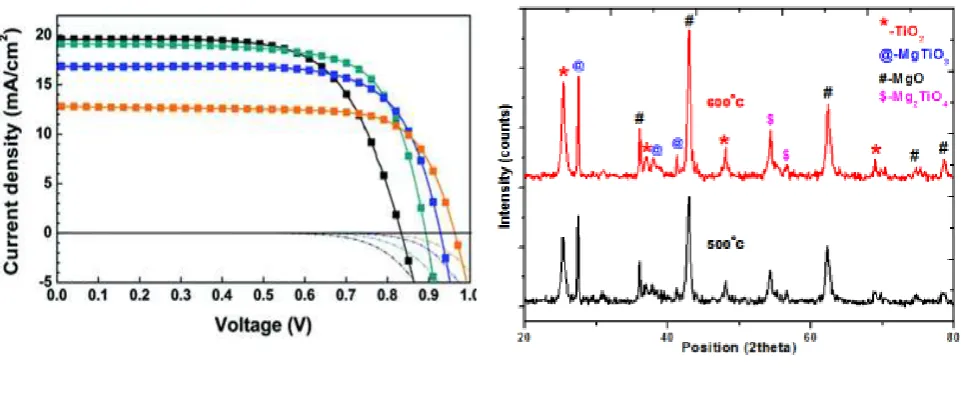
Figure 3 shows I–V curves for TiO2 and TiO2/MgO in the dark and under illumination with a light intensity of 60 mW cm−2. The corresponding solar cell parameters were summarized in table 1. Compared with TiO2, the TiO2 sputtering MgO for 3 min (TiO2/MgO 3 min) electrode gives higher short-circuit photocurrent (Jsc), open-circuit photovoltage (Voc) and fill factor (FF). The efficiency is significantly enhanced from 6.45 to 7.57%. It shows the merits DSSCs. Upon increasing sputtering time to 15 min, the Voc and FF further increase but Jsc decreases, resulting in the decreased conversion efficiency. On increasing sputtering time to 30 min, due to the drastic drop of all parameters, the TiO2/MgO 30 min cell gives poor conversion efficiency. It indicated that the excessively thick MgO layer beyond the tunneling distance plays a negative of TiO2/MgO electrodes by reactive DC magnetron sputtering in improving the performance of role in the photoelectron conversion process.
Fig 1.current and voltage of Tio2/Mgo Fig 2: XRD of Tio2/Mgo
(JCPDS Card No. 07-6173). The peaks are very sharp, implying that the TiO2 films were well crystallized. The XRD pattern (not shown here) of the MgO coated TiO2 film is found to be similar as that of pure TiO2 film. No separate MgO phase is detected in the sample due to the extremely thin MgO layer.
Fig4.Sem Image of coreshell
Electrode
J
sc(mA cm−2)V
oc(V)FFη (%)TiO28.740.6620.6696.45TiO2/MgO 3 min9.510.6820.7007.57. TiO2/MgO 15 min7.160.7010.7165.99 TiO2/MgO 30 min4.470.6430.6483.10
addition, the dark currents for the DSSCs were measured and are shown in figure 3. It can be seen that the dark currents change slightly while the magnitude of the dark current is reduced to some extent in TiO2/MgO 3 min and TiO2/MgO 15 min cells. The variations of dark current explain the fact that the Voc is not changed noticeably. The dark current at potentials more negative than that of TiO2 is reduced in TiO2/MgO 3 min and TiO2/MgO 15 min, which also indicates that the reaction between triiodides and conduction band electrons is suppressed. Based on these results, it can be seen that the cell performance is so sensitive that an appropriate sputtering time is needed in the DSSCs. More detailed analyses were carried out to understand the properties of TiO2/MgO.
Since DSSCs were illuminated from the FTO substrate side in working conditions, we carried out absorption and transmission spectra of TiO2 and TiO2/MgO. As shown in figure 4, the absorption and transmission spectra indicate that dye-free TiO2/MgO 3 min has almost the same spectra as TiO2. However, the TiO2/MgO 3 min cell gives better Jsc, Voc and FF, which indicates that the increase of Jsc is not due to the higher light harvest.
supported by the absorption spectra in figure 5. As shown in figure 5, since the degree of dye adsorption on the electrode is proportional to the intensity of the optical adsorption of the dye, TiO2/ MgO electrodes apparently enhance the dye adsorption with increasing sputtering time, which suggests the merit of TiO2/ MgO electrodes.
IV.CONCLUTION
In summary, a surface modification method based on TiO2 electrodes coated with MgO was successfully developed in DSSCs by reactive DC magnetron sputtering. The study results show that the O2 plasma treatment and MgO coating in the sputtering increases dye adsorption, decreases trap states and suppresses charge recombination at the TiO2 /dye/electrolyte interface. Sputtering MgO for 3 min on TiO2 increases all cell parameters, resulting in improving efficiency.
REFERENCES
[1] O’Regan B and Grätzel M 1991 Nature 353 737-40
[2] Palmars E, Clifford J N, Haque S A, Lutz T and Durrant J R 2002 Chem. Commun. 1464-5
[3] Wang Z-S, Yanagida M, Sayama K and Sugihara H 2006 Chem. Mater. 18 2912-6
[4] Wu X, Wang L, Luo F, Ma B, Zhan C and Qiu Y 2007 J. Phys. Chem. C 111 8075-9
[5] Wang Z-S, Huang C H, Huang Y Y, Hou Y J, Xie P H, Zhang B W and Cheng H M 2001 Chem. Mater. 13 678-82
[6] Chappel S, Chen S and Zaban A 2002 Langmiur 18 3336-42
[7] Yang S M, Huang Y Y, Huang C H and Zhao X S 2002 Chem. Mater. 14 1500-4
[8] Chen S G, Chappel S, Diamant Y and Zaban A 2001 Chem. Mater. 13 4629-34
[9] Palomares E, Clifford J N, Haque S A, Lutz T and Durrant J R 2003 J. Am. Chem. Soc. 125 475-82
[10] Diamant Y S, Chen S G, Melamed O and Zaban A 2003 J. Phys. Chem. B 107 1977-81
[11] Roh S J, Mane R S, Min S K, Lee W J, Lokhande C D and Han S H 2006 Appl. Phys. Lett. 89 253512
[12] Ahn K-S, Kang M S, Lee J K, Shin B C and Lee J W 2006 Appl. Phys. Lett. 89 013103
[13] Nanu M, Schoonman J and Goossens A 2004 Adv. Mater. 16 453-6
[14] Yun J H Nakade S, Kim D and Yanagida S 2006 J. Phys. Chem. B 110 3215-9
[15] Alarcon H, Hedlund M, Johansson E M J, Rensmo H, Hagfeldt A and Boschloo G 2007 J. Phys. Chem. C 111 13267-74\
[16] Kay A and Grätzel M 2002 Chem. Mater. 14 2930-5
[17] Alarcon H, Boschloo G, Mendoza P, Solis J L and Hagfeldt A 2005 J. Phys. Chem. B 109 18483-90
[18] Han J-B, Wang N, Yu G-P, Wei Zh-H, Zhou Zh-G and Wang Q-Q 2005 Sol. Energy Mater. Sol. Cells 88 293-99
[19] Han J-B, Wang X, Wang N, Wei Zh-H, Yu G-P, Zhou Zh-G and Wang Q-Q 2006 Surf. Coat. Technol. 200 4876-8
[20] Kim Y, Yoon C, Kim K and Lee Y 2007 J. Vac. Sci. Technol. A 25 1219-2\
[21] Kim Y, Yoo B, Vittal R, Lee Y, Park N-G and Kim K-J 2008 J. Power Sources 175 914-9
[22] Bandara J, Hadapangoda C C and Jayasekera W G 2004 Appl. Catal. B 50 83-8
[24] Bandaranyake K M P, Senevirathna M K I, Weligamuwa P M G M P and Tennakone K 2004 Coord. Chem. Rev. 248 1277-81
[25] Willis R L, Olson C, O’Regan B, Lutz T, Nelson J and Durrant J R 2002 J. Phys. Chem. B 106 7605-13
[26] Nazeeruddin M K, Splivallo R, Liska P, Comte P and Grätzel M 2003 Chem. Commun. 1456-7
[27] Nazeeruddin M K, Kay A, Rodicio I, Humphry-Baker R, Müller E, Liska P, Vlachopoulos N and Grätzel M 1993 J. Am. Chem. Soc. 115 6382-90
[28] Shoute L C T and Loppnow G R 2003 J. Am. Chem. Soc. 125 15636-46
[29] Kruger J, Plass R, Gratzel M and Matthieu H-J 2002 Appl. Phys. Lett. 81 367-9
[30] Zhang Z-P, Zakeeruddin S M, O’Regan B C, Humphrey-Baker R and Grätzel M 2005 J. Phys. Chem. B 109 21818-24
[31] Moser J, Punchihewa S, Infelta P P and Grätzel M 1991 Langmuir 7 3012-8
[32] Lee S, Kim J Y, Youn S H, Park M, Hong K S, Jung H S, Lee J-K and Shin H 2007 Langmuir 23 11907-10
[33] Fukai Y, Kondo Y, Mori S, et al. Highly efficient dye-sensitized SnO2 solar cells having sufficient electron diffusion length[J]. Electrochem Commun, 2007, 9: 1439-1443.
[34] Chen Z G, Tang Y W, Zhang L S, et al. Electrodeposited nanoporous ZnO films exhibiting enhanced performance in dye-sensitized solar cells[J]. Electrochim Acta, 2006, 51: 5870- 5875.
[35] Hagfeldt A, Grätzel M. Ligh-induced redox reactions in nanocrystalline systems[J]. Chem Rev, 1995, 95: 49-68.
[36] Hagfeldt A, Lindquist S E, Grätzel M. Charge carrier separation and charge transport in nanocrystalline junctions[J]. Sol Energy Mater Sol Cells, 1994, 32: 245-257.
[37] Tachibana Y, Moser J E, Grätzel M, et al. Subpicosecond interfacial charge separation in dye-sensitized nanocrystalline titanium dioxide films[J]. J Phys Chem, 1996, 100: 20056- 20062.
[38] Diamant Y, Chen S G, Melamed O, et al. Core-shell nanoporous electrode for dye sensitized solar cells: the effect of the SrTiO3 shell on the electronic properties of the TiO2 core[J]. J Phys Chem B, 2003, 107: 1977-1981.
[39] Zhang X T, Sutanto I, Taguchi T, et al. Al2O3-coated nanoporous TiO2 electrode for solid-state dye-sensitized solar cell[J]. Sol Energy Mater Sol Cells, 2003, 80: 315-326.
[40] Chen S G, Chappel S, Diamant Y, et al. Preparation of Nb2O5 coated TiO2 nanoporous electrodes and their application in dye-sensitized solar cells[J]. Chem Mater, 2001, 13: 4629- 4634.
[41] Menzies D B, Bourgeois L, Cheng Y B, et al. Characterization of nanostructured core-shell working electrodes for application in dye-sensitized solar cells[J]. Surf Coat Technol, 2005, 198: 118-122.
[43] Kumara G R A, Okuya M, Murakami L, et al. Dye-sensitized solid-state solar cells made from magnesiumoxide-coated nanocrystalline titanium dioxide films: enhancement of the efficiency[J]. J Photochem Photobiol A, 2004, 164: 183-185.
[44] Taguchi T, Zhang X T, Sutanto I, et al. Improving the performance of solid-state dye-sensitized solar cell using MgOcoated TiO2 nanoporous film[J]. Chem Commun, 2003, (19): 2480- 2481.
[45] [44] O’Regan B, Grätzel M. A low-cost, high-efficiency solar cell based on dye-sensitized colloidal TiO2
films[J]. Nature, 1991, 353: 737-739.
[46] G. Eason, B. Noble, and I.N. Sneddon, “On certain integrals of Lipschitz-Hankel type involving products of Bessel functions,” Phil. Trans. Roy. Soc. London, vol. A247, pp. 529-551, April 1955. (references)
[47] J. Clerk Maxwell, A Treatise on Electricity and Magnetism, 3rd ed., vol. 2. Oxford: Clarendon, 1892, pp.68-73.
[48] I.S. Jacobs and C.P. Bean, “Fine particles, thin films and exchange anisotropy,” in Magnetism, vol. III, G.T. Rado and H. Suhl, Eds. New York: Academic, 1963, pp. 271-350.
[49] K. Elissa, “Title of paper if known,” unpublished.
[50] R. Nicole, “Title of paper with only first word capitalized,” J. Name Stand. Abbrev., in press.
[51] Y. Yorozu, M. Hirano, K. Oka, and Y. Tagawa, “Electron spectroscopy studies on magneto-optical media and plastic substrate interface,” IEEE Transl. J. Magn. Japan, vol. 2, pp. 740-741, August 1987 [Digests 9th Annual Conf. Magnetics Japan, p. 301, 1982].