Analytical Method for Calculation of Cogging Torque Reduction
Due to Slot Shifting in a Dual Stator Dual Rotor Permanent
Magnet Machine with Semi-Closed Slots
Praveen Kumar*, Md M. Reza, and Rakesh K. Srivastava
Abstract—Radial flux Dual Stator Dual Rotor Permanent Magnet (DSDRPM) machine can be considered as an exterior rotor Permanent Magnet (PM) machine kept over an interior rotor PM machine. This facilitates with a scope for optimization of the relative placement of inner and outer stator slots of the machines to achieve cogging torque minimization. This paper deals with the analytical prediction of flux density distribution in an internal and external rotor PM machines with semi-closed slots and further utilizes it to calculate the cogging torque in DSDRPM machine. An optimal angle of shift between the stator slots of the two machines has been determined to obtain a reduction in the resultant cogging torque of DSDRPM machine. The analytical results are verified with the Finite Element Analysis (FEA) results and found to be in close agreement with each other.
1. INTRODUCTION
The emergence of rare earth permanent magnets in the recent past has engendered the development of high torque, high power density permanent magnet machines. In view of this, the use of two PM rotors in a machine will further increase the torque and power capability of the machine. The potential application of dual-rotor PM machine can be the in-wheel motor drive for Electric Vehicles (EV) due to its compactness, light weight and high torque to weight ratio. Such machines with enhanced torque capability are much efficient and can prove its suitability in varied industrial, automotive and power generation applications. In all such applications, especially in direct-drive EVs, smooth and noiseless operation is a prerequisite. However, owing to the presence of permanent magnets, a well-known phenomenon called cogging is inherent in PM machines, which introduces torque ripples, vibrations and noise, thus, obstructing its smooth operation. Cogging may be more pronounced in double rotor PM machines if not designed properly. In view of this, cogging torque minimization in DSDRPM machines is of much significance.
Several methods have been suggested till now for cogging torque reduction in PM machines. The techniques such as slot skewing [1–4], magnet skewing [1, 3, 5], tooth shape variation [4, 6], slot opening variation [1, 4–6], magnet shape variation [5, 7], optimizing magnet pole arc to pole pitch ratio [1, 5, 6, 8], etc., can be applied to both radial and axial flux PM machines. However, very few papers have been reported on cogging minimization techniques in DSDRPM machines. In [6], Qu and Lipo proposed a dual-rotor Radial Flux Toroidally wound PM (RFTPM) machine and suggested three approaches to reduce cogging, namely, slot opening shifting, varying slot opening angular width, and PM angular width variation. The method was validated using FEA results and experimental measurements. Since the machine can be considered as an interior PM machine nested inside an exterior PM machine, with
Received 5 May 2018, Accepted 22 June 2018, Scheduled 10 July 2018 * Corresponding author: Praveen Kumar ([email protected]).
This paper suggests a method for cogging torque minimization in radial flux DSDRPM machine by assuming the machine as an outer rotor machine kept over an inner rotor machine and making a relative angular shift between the inner and outer stator slots. The slots can be displaced with respect to each other in steps and cogging torque because inner and outer rotor machines can be calculated separately at each step. The resultant cogging torque being the algebraic sum of the two torques can be obtained by the superposition of cogging torque due to inner and outer rotor machines. An optimal displacement between the inner and outer slots can be determined to achieve a position of minimum resultant cogging torque. For precise determination of this optimal displacement, analytical or numerical techniques can be adopted. In this paper, an analytical model has been developed to calculate the cogging torque for various relative angular displacements between inner and outer stator slots and obtain an optimal angular shift at which cogging is minimum. The numerical technique based Finite Element method has been used to validate the analytical results. In the next section, the models of internal and external rotor PM machines having semi-closed slots have been developed. The magnetic field distribution due to magnets in both the machines has also been obtained considering the effect of slotting. Section 3 describes the analytical calculation of cogging torque and its minimization technique, which is the main contribution of this paper. Results and discussions are covered in Section 4. Section 5 finally concludes the paper.
2. FIELD DISTRIBUTION DUE TO MAGNETS IN DSDRPM MACHINE WITH SEMI-CLOSED SLOTS
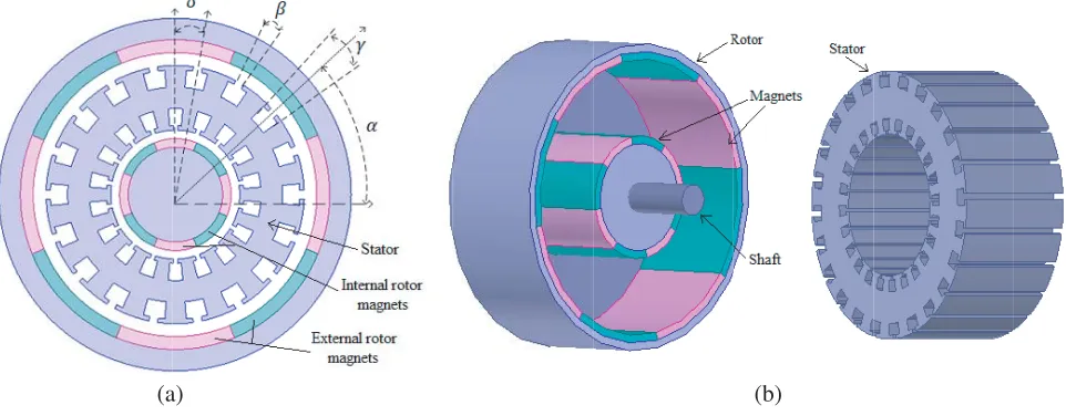
The model of a DSDRPM machine consisting of inner and outer PM rotors and an intermediate stator with semi-closed slots at both inner and outer peripheries is shown in Figure 1. The stator is fixed to a stationary frame while the inner and outer PM rotors are mechanically coupled to each other as well as to the output shaft through an end plate. Both the rotors have 8 PM poles. The stator may have separate 3 phase distributed windings in the inner and outer slots. The windings of the inner and outer stators may be connected either in series or parallel depending on the specific application rating. Toroidal winding may also be used for such a type of stator structure as discussed in [6]. The windings of the machine are fed with 3 phase inverters to provide a proper switching sequence for starting and operation.
The magnetic field distribution produced by permanent magnets in a DSDRPM machine can be obtained by solving the governing equations in the slotless geometry of the machine and then multiplying
(a) (b)
(a) (b)
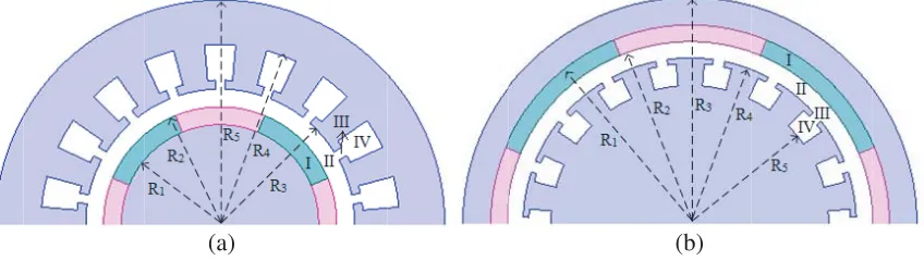
Figure 2. (a) Internal rotor PM machine. (b) External rotor PM machine.
the obtained field distribution by a permeance function to account for slotting effect. Alternatively, it can also be determined using subdomain method which gives more accurate results.
As discussed earlier, the DSDRPM machine is considered as a combination of an internal and external rotor PM machines sharing a common stator. So, to obtain the field distribution inside it, instead of solving it as a single machine, the two machines can be solved independently, and their fields can be superimposed to obtain the resultant field distribution.
The models of the two machines used for analysis are shown in Figure 2. In Figure 1(a),αrepresents the initial angle of jth slot from the reference position, β the angular slot opening, γ the angular slot width, and δ the relative angular shift between inner and outer stator slots. For both machines, the field solution is obtained in each subdomain, viz. magnet (I), air gap (II), slot opening (III) and slot (IV). The analysis is done using the following assumptions.
1) Stator and rotor iron cores have infinite permeability. 2) The magnets are radially magnetized.
3) The machine is assumed to be unsaturated.
In the present case, the DSDRPM machine is considered as two separate machines, and the field analysis is confined to the above-discussed regions of both machines as shown in Figure 2. The field vectors B and H are linked together by the following set of equations:
Bi = μ0μirHi+μ0M i∈I (1a)
Bi = μ0Hi i∈II (1b)
where M is the remnant magnetization of permanent magnets, and μIr and μ0 are the relative
permeability of magnet and air gap region, respectively. The magnetization vector M in polar coordinates is given by
M =Mrr+Mθθ (2)
where r and θ denote the direction vectors in the radial and tangential directions. The radial magnetization componentsMr may be expanded into the Fourier series as follows:
Mr=
∞
n=1,3.5...
Mrncos (npθ) (3)
where n is the number of harmonics, p the number of pole-pairs, and θ the variable spatial (or mechanical) angle.
Mrn=
4Br
μ0nπ
sin
nπαp
2
(4)
whereαp = θθm
Br = ∂Ar∂θz (5a)
Bθ = −∂A∂rz (5b)
The governing field equations in the given regions are defined as
∇2A iz =
−μ0(∇ ×M); i∈I
0; i∈II, III, IV (6)
The above equation can be expressed in polar form as
∂2A I
∂r2 +
1 r ∂AI ∂r + 1 r2
∂2A I
∂θ2 = −
∞
n=1,3,5...
μ0Mrn
r sin (npθ) (7a)
∂2A i
∂r2 +
1 r ∂Ai ∂r + 1 r2
∂2A i
∂θ2 = 0 i∈II, III, IV (7b)
The boundary conditions at the interfaces of various subdomains of internal and external rotor PM machines are as given in Equation (8). The continuity of radial component of flux density at various interfaces leads to
AI(R2, θ) =AII(R2, θ) ; AII(R3, θ) =AIII(R3, θ) ; AIII(R4, θ) =AIV (R4, θ) (8a)
The tangential component of flux density at the sides of slots and slot openings is null as stator core permeability is assumed to be infinite. This leads to
∂AIII
∂θ
θ=α−β
= 0; ∂AIII ∂θ θ=α+β = 0 ∂AIV ∂θ θ=α−γ
= 0; ∂AIV ∂θ θ=α+γ = 0 (8b)
At the inner and outer boundaries of both machines, the boundary conditions can be defined as
∂AI
∂r
r=R1
= 0; ∂AIV ∂r
r=R5
= 0 (8c)
The general solution of Equation (7) for both machines can be stated as [9, 10]: For PM subdomain,
AI(r, θ) = ∞
n=1
a1nrnp+b1nr−np− Mrnr
1−(np)2
cos (npθ)
+ ∞
n=1
c1nrnp+d1nr−np− Mrnr
1−(np)2
sin (npθ) (9a)
For air gap subdomain,
AII(r, θ) = ∞
n=1
a2nrnp+b2nr−np
cos (npθ) + ∞
n=1
a2nrnp+b2nr−np
sin (npθ) (9b)
Forith slot opening subdomain,
AiIII(r, θ) =Aio+Boilnr+ ∞
m=1
a3nr
mπ
2β −b3nr−mπ2β
cos mπ
2β (θ−α+β)
Forjth slot subdomain,
AjIV (r, θ) =Ajo+ μoJj 2
R25lnr−
r2 2
∞
k=1
Ajm
a4nr
kπ
2γ −b4nr−kπ2γ
cos kπ
2γ (θ−α+γ)
(9d)
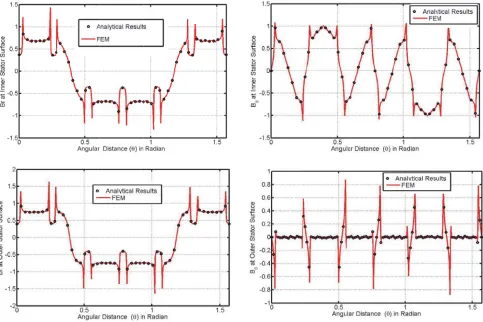
The coefficients of Equation (9) can be obtained by using the boundary conditions given in Equation (8) and are defined in [11]. The radial and tangential components of the flux density in various subdomains can be calculated using Equation (5). Thus, the analytical method discussed here is helpful in determining the flux density components in both the internal and external rotor PM machines. The analytical plots of radial and tangential components of flux density at the stator surface of the two machines for the parameters given in Table 1 are shown in Figure 3.
Figure 3. Radial and tangential components of flux density at the inner and outer stator surface of DSDRPM machine for NS configuration.
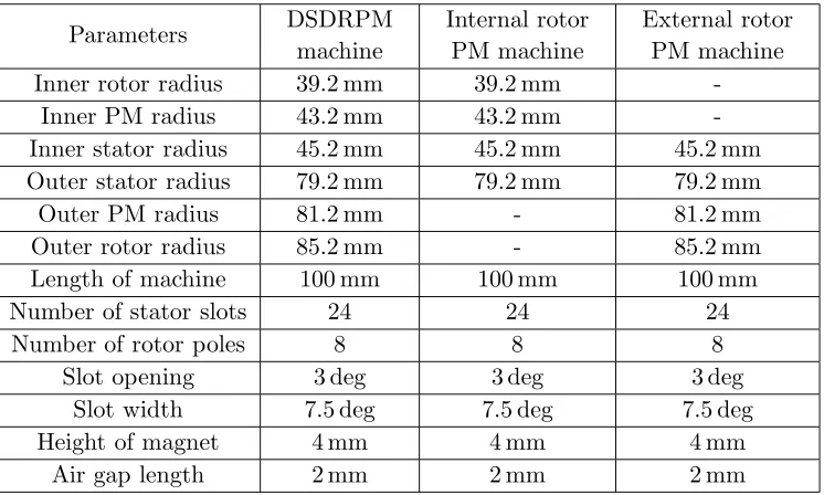
The flux density distribution inside the two machines should match with that obtained when the two are merged to obtain DSDRPM machine, which is the machine under consideration. Thus, the modeling of DSDRPM machine with semi-closed slots is done on Ansoft Maxwell software using the parameters given in Table 1 to obtain its numerical based solution. The FEM results are obtained for the inner and outer slots kept in aligned position, i.e., for δ= 0 in Figure 1.
Parameters DSDRPM machine
Internal rotor PM machine
External rotor PM machine Inner rotor radius 39.2 mm 39.2 mm
-Inner PM radius 43.2 mm 43.2 mm -Inner stator radius 45.2 mm 45.2 mm 45.2 mm Outer stator radius 79.2 mm 79.2 mm 79.2 mm
Outer PM radius 81.2 mm - 81.2 mm
Outer rotor radius 85.2 mm - 85.2 mm Length of machine 100 mm 100 mm 100 mm
Number of stator slots 24 24 24
Number of rotor poles 8 8 8
Slot opening 3 deg 3 deg 3 deg
Slot width 7.5 deg 7.5 deg 7.5 deg
Height of magnet 4 mm 4 mm 4 mm
Air gap length 2 mm 2 mm 2 mm
of flux density reaches maximum at the tooth edges due to maximum leakage at the edges. Since the FEM results validate the analytical results, the analytical field equations developed can be successfully utilized to calculate the cogging torque in DSDRPM machine.
3. COGGING TORQUE CALCULATION AND ITS MINIMIZATION
Various methods have been proposed till now for the calculation of cogging torque in a PM machine. A general approach to cogging torque determination involves the calculation of net lateral force acting on the stator teeth. For this, very accurate field solution is required in the stator tooth and slot regions. Although the numerical method provides sufficient accuracy, numerical errors are introduced due to the finite discretization of the computational domains at the slot sides [12, 13]. However, the analytical prediction of cogging torque using complex permeance [14] or subdomain methods [11, 15] provide very accurate results.
In most of the available literature, the cogging torque is calculated in a single step by utilizing the resultant air gap flux density distribution. However, the authors in [16, 17] used the cogging torque due to a single slot to obtain the resultant cogging torque using superposition method. In [12] also, the synthesis of resultant cogging torque using the cogging torque due to a single slot has been discussed. Yet all these calculations were limited to open slot machines.
In this paper, subdomain method was used for the precise calculation of radial and tangential components of flux density in the internal and external rotor machines with semi-closed slots, as already discussed. The accuracy of these flux density components can be propagated to cogging torque calculation in both the machines using Maxwell stress tensor [18] and is given as
Tc= Lr
2
2μo
2π
0
BrBθdθ (10)
Figure 4. Cogging torque in 24 slots 8 pole internal rotor PM machine.
Figure 5. Cogging torque in 24 slots 8 pole external rotor PM machine.
The cogging torque in inner and outer machines due to a single slot can be represented as
Tcsi = ∞
h=1
Tihsin 2phθ (11a)
Tcso = ∞
h=1
Tohsin 2phθ (11b)
The resultant cogging torque due to Qs number of stator slots in each machine can be calculated by
the superposition of cogging torque due to a single slot [12]. Since the DSDRPM machine was assumed as an internal rotor PM machine nested inside an external rotor PM machine sharing a common stator core, their cogging torque in a common reference frame can be expressed as
Tci = Qs
k=1
∞
h=1
Tihsin 2ph
θ+ 2π
Ns(k−1)
(12a)
Tco =
Qs
k=1
∞
h=1
Tohsin 2ph
θ+ 2π
Ns(k−1) +δ
(12b)
where Tci and Tco are the resultant cogging torques in the internal and external rotor machines,
respectively, and Tih and Toh are the peak values of cogging torque due to a single slot. Qs is the
number of stator slots, 2p the number of poles, andδ the angle of displacement between the stator of inner and outer rotor machines.
The resultant cogging torque in DSDRPM machine can be obtained by the superposition of cogging torques due to the internal and external rotor machines. The validity of the superposition can be justified as there is no air gap between the two stators, and the stator core is infinitely permeable. Thus, the resultant cogging torque can be represented as
Tcr =Tci+Tco (13)
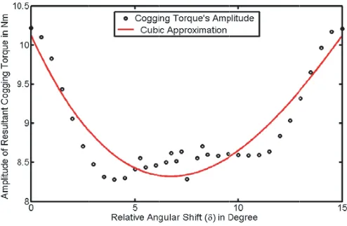
This furnishes a scope for cogging torque minimization in DSDRPM machine. From this prospect, the outer machine stator can be slid over inner machine stator to vary the angle δ, between the inner and outer stator slots. This angular drift in small steps can serve as a significant tool to obtain an optimal angular shift for minimal cogging torque in DSDRPM machine. It is also clear from Equations (13) and (14) that forδ = 0, the resultant cogging torque,Tcr, is maximum. Asδ increases, the peak ofTcr
Figure 6. Variation of the peak of resultant cogging torque withδ.
4. RESULTS AND DISCUSSIONS
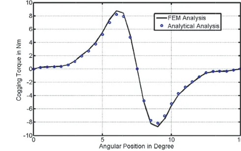
The plot of cogging torque waveform for internal and external rotor machine shown in Figure 4 and Figure 5 reveals that the peak value of cogging torque in internal rotor machine is much less than that in the external rotor machine. As stated earlier, when the two machines are merged in a way that the centers of their slots are aligned (δ= 0), the peaks of cogging torque waveforms of the two machines are also in phase as shown in Figure 7. Thus, an enhanced resultant cogging torque having a peak value of 10.2 N-m is obtained for the resulting DSDRPM machine. If the stator of the outer machine is shifted from this position relative to the inner stator, the peak of the cogging torque waveform of the outer machine also gets relocated accordingly. For a mechanical angular shift of outer stator by 7.5 degrees from the aligned position, the cogging torque waveforms of the two machines along with the resultant waveform are depicted in Figure 8. At this position, the maximum reduction in the resultant cogging torque has been achieved. The values of cogging torque and the reduction achieved are summarized in Table 2. For a shift greater than this angle, the resultant cogging torque again tends to increase. Thus, an optimal angular shift between the stators of the two machines or the inner and outer stator slots of DSRRPM machine has been attained using the analytical method discussed here. The validity of the obtained results is verified with 2-D FEM results obtained using Ansoft Maxwell platform, and their close agreement can be seen from various plots.
Figure 7. The resultant cogging torque of the two machines for δ= 0.
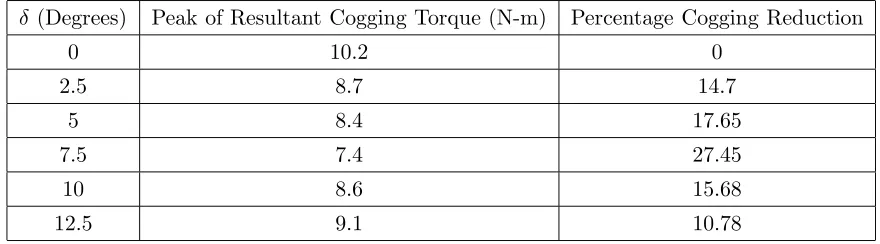
Table 2. Cogging torque variation withδ.
δ (Degrees) Peak of Resultant Cogging Torque (N-m) Percentage Cogging Reduction
0 10.2 0
2.5 8.7 14.7
5 8.4 17.65
7.5 7.4 27.45
10 8.6 15.68
12.5 9.1 10.78
5. CONCLUSION
This paper discusses the subdomain approach for the calculation of no-load flux density distribution in a radial flux Dual Stator Dual-Rotor PM machine with semi-closed slots. Analytical calculation of cogging torque and its reduction by relative shifting of the inner and outer stator slots is established. The analytical expressions developed facilitate their usefulness for design optimization of the relative position of stator slots to achieve minimum cogging in DSDRPM machine. It is found that a relative mechanical angular shift between the inner and outer stator slots by 7.5 degrees results in the reduction of cogging torque of the machine by 27.45 percent. Thus, it can be established that maximum reduction in cogging torque in a DSDRPM machine can be achieved by relative shifting of inner and outer stator slots by a half slot pitch. The analytical results are compared with FEM results, and their close agreement verifies the analytical solution. Thus, a faster and more accurate method compared to FEM, which can be helpful in determining and reducing cogging torque in semi-closed slotted DSDRPM machine, has been developed.
REFERENCES
1. Zhu, Z. Q. and D. Howe, “Influence of design parameters on cogging torque in permanent magnet machines,”IEEE Trans. Energy Convers., Vol. 15, No. 4, 407–412, Dec. 2000.
2. Hanselman, D. C., “Effect of skew, pole count and slot count on brushless motor radial force, cogging torque and back EMF,” Proc. Inst. Elect. Eng. — Electr. Power Appl., Vol. 144, No. 5, 325–330, Sep. 1997.
3. Bianchi, N. and S. Bolognani, “Design techniques for reducing the cogging torque in surface-mounted PM motors,” IEEE Transactions on Industry Applications, Vol. 38, No. 2, 1259–1265, Sep./Oct. 2002.
4. Wanjiku, J., M. A. Khan, P. S. Barendse, and P. Pillay, “Influence of slot openings and tooth profile on cogging torque in axial-flux PM machines,” IEEE Trans. Ind. Electron., Vol. 62, No. 12, 7578–7589, Dec. 2015.
5. Aydin, M., Z. Q. Zhu, T. A. Lipo, and D. Howe, “Minimization of cogging torque in axial-flux permanent-magnet machines: Design concepts,” IEEE Transactions on Magnetics, Vol. 43, No. 9, 3614–3622, Sep. 2007.
6. Qu, R. and T. A. Lipo, “Dual-rotor, radial flux, toroidally wound, permanent-magnet machines,”
IEEE Transactions on Industry Applications, Vol. 39, No. 6, 1665–1673, Nov./Dec. 2003.
7. Chang, S. K., S. Y. Hee, W. N. Ki, and S. C. Hong, “Magnetic pole shape optimization of permanent magnet motor for reduction of cogging torque,” IEEE Transactions on Magnetics, Vol. 33, No. 2, 1822–1827, Mar. 1997.
No. 12, paper ID: 8114910, Dec. 2015.
10. Binns, K. J. and P. J. Lawrenson, Analysis and Computation of Electric and Magnetic Field Problems, Pergamon Press, 1973.
11. Lubin, T., S. Mezani, and A. Rezzoug, “2-d exact analytical model for surface-mounted permanent-magnet motors with semi-closed slots,” IEEE Transactions on Magnetics, Vol. 47, No. 2, 479–492, 2011.
12. Zhu, Z. Q., S. Ruangsinchaiwanich, and D. Howe, “Synthesis of cogging-torque waveform from analysis of a single stator slot,” IEEE Transactions on Industry Applications, Vol. 42, No. 3, 650– 657, 2006.
13. Howe, D. and Z. Q. Zhu, “The influence of finite element discretization on the prediction of cogging torque in permanent magnet excited motors,” IEEE Transactions on Magnetics, Vol. 42, No. 2, 1080–1083, 1992.
14. Zarko, D., D. Ban, and T. A. Lipo, “Analytical calculation of magnetic field distribution in the slotted air gap of a surface permanent-magnet motor using complex relative air-gap permeance,”
IEEE Transactions on Magnetics, Vol. 42, No. 7, 1828–1837, 2006.
15. Wu, L., Z. Zhu, D. Staton, M. Popescu, and D. Hawkins, “An improved subdomain model for predicting magnetic field of surface-mounted permanent magnet machines accounting for tooth-tips,” IEEE Transactions on Magnetics, Vol. 47, No. 6, 1693–1704, 2011.
16. Zhu, Z. Q. and D. Howe, “Analytical prediction of the cogging torque in radial-field permanent magnet brushless motors,”IEEE Transactions on Magnetics, Vol. 28, No. 2, 1080–1083, Mar. 1992. 17. Proca, A. B., A. Keyhani, A. E. Antably, W. Lu, and M. Dai, “Analytical model for permanent magnet motors with surface mounted magnets,” IEEE Trans. Energy Convers., Vol. 18, No. 3, 386–391, Sep. 2003.
18. Kumar, P. and P. Bauer, “Improved analytical model of a permanent-magnet brushless DC motor,”