A New Active Power Factor Correction
Controller Using Cuk Converter
Brijesha Patel 1, Jay Patel 2, Umang Wani 2
PG Student [Power System], Dept. of EE, CGPIT College, Bardoli, Gujarat, India1
Assistant Professor, Dept. of EE, CGPIT College, Bardoli, Gujarat, India2
Assistant Professor, Dept. of EE, CGPIT College, Bardoli, Gujarat, India2
ABSTRACT: Cuk converter is dc-dc converter; it can be used for step up and step down the voltage by varying duty ratio. Cuk converter has low ripples in output. Cuk converter can use for power factor correction application by operating in discontinuous mode, there switching occurs in zero values of current. Here discontinuous means current approaches to zero, when supply voltage and current are in phase, power factor approaches nearer to unity. High frequency switching dc-dc converters is new technology to control load and supply side simultaneously. Due to additional harmonics generated by these switching converters power factor correction has become necessity in utility side. This paper focuses on controlling of power factor correction employing high switching frequency dc-dc converters with this, explanation of converter controlled loop and its strategy is also briefed. The simulated results have been shown to ascertain accepted performance of power factor correction converter.
KEYWORDS: Average Current Control, Cuk Converter, Control Techniques, Hysteresis Control, Linear Loads, MATLAB(student version), Peak Current Control, PI Controller, PID Controller, Power Factor, Power Factor Correction.
I. INTRODUCTION
Nowadays power supplies with active power correction techniques are required for wide range of applications for
communications, automotive, computer and biomedical industries. Power supplies with active power factor correction techniques are becoming more necessary for many types of electronic equipment to meet harmonic regulations and some standards.
Most of power factor correction rectifiers uses boost converter at their front end. Boost converter provides many advantages such as natural power factor correction capability and simple control. However, low voltage applications such as telecommunications or computer industry additional converter or isolation transformer is required to step down voltage. In addition, boost converters suffer from high inrush current which increases the cost of safety required disconnection devices between load and line voltage.
Cuk converter topology is typically lower efficiency converter; however it presents many advantages, such as isolation capability, step up/step down output voltage, continuous output current and lower ripple factor. In this paper, high efficiency cuk topology is proposed. The proposed topology performance is evaluated based on component count, efficiency, total harmonic distortion and complexity. The proposed topology has low ripple factor.
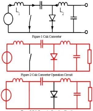
II. CUK CONVERTER
Cuk Converter is dc-dc converter , it can step up and step down voltage according to variation in duty ratio,
= 1−
The cuk converter allows energy to flow bidirectional by using diode and switch. The cuk converter comprises of two inductors, two capacitors, switch used as transistor, diode.
Vol. 5, Issue 4, April 2016
Figure 1 Cuk Converter
Figure 2 Cuk Converter Operation Circuit
Figure 3 Cuk Converter Operation Circuit
The two inductors and are used to convert respectively input voltage source and output voltage source into current
source. In short time inductor can be considered as current source as it maintains constant current. Charging capacitor with current source prevents resistive current limiting and its associated energy loss.
Cuk converter can either be operated in continuous or discontinuous current mode. However it can be operated in voltage discontinuous mode.
Continuous Mode: In steady state, energy stored in inductors has to remain same at beginning and at commutation cycle. The energy in inductor is
=1 2
This implies that current through inductors has to be same at beginning and end of commutation cycle. As evolution of current through inductor is related to voltage across it:
=
It can be seen that average value of inductor voltages over commutation period have to be zero to satisfy steady state requirements.
In off state, inductor is connected in series with and C. Therefore = − . As diode D is forward biased, is directly connected to output capacitor. Therefore = .
In on state, inductor is directly connected to input source. Therefore = . Inductor is connected in series with C and output capacitor, so = + .
The converter operates in on state from t = 0 to t = D·T (D is duty Cycle), and in off state from D·T to T. The average
value of and are therefore:
= ∙ + (1− )∙ − = ( − (1− ) ∙ )
= ( + ) + (1− )∙ = ( + ∙ )
As both average voltages have to be zero to satisfy steady state conditions, using last equation we can write:
=−
So average voltage across becomes:
= + (1− )∙ = 0 Which can be written as:
= − 1−
Discontinuous Mode: Like all dc-dc converters ability of inductors in circuit to provide continuous current, in much same way capacitor in rectifier filter provides continuous voltage. If this inductor is too small, then current will be discontinuous.
The minimum inductance is given by:
=(1− ) 2
Where is switching frequency.
III. POWER FACTOR CORRECTION
The quality of absorbed from utility line by electronic equipment is increasing due to several reasons. In fact, low power factor reduces the power available from utility grid, while high harmonic distortion of line current which causes and cross-interferences, through the line current impedance, between different systems connected to a same grid. An ideal power factor should emulate resistor on supply side while maintaining regulated output voltage. In case of sinusoidal line voltage, means that converter must draw sinusoidal current from utility; in order to do that, suitable sinusoidal reference is generally needed and control objective is to force input current to follow as possible to reference current.
IV. RESULTS AND DISCUSSION
This paper involves simulation of simple circuits with gradual increase in complexity by inclusion of new components. All simulation work is done in MATLAB Simulink. First I have explained only cuk converter without any technique. Then its THD calculation and ripple factor. Then I have shown different control techniques using cuk converter. So, results shows that without control technique power factor is not improved and also THD is very high and ripple factor is high. So to improve power factor, THD and ripple factor, I have selected few control techniques.
The simulations of simple cuk converter using control techniques are shown as below.
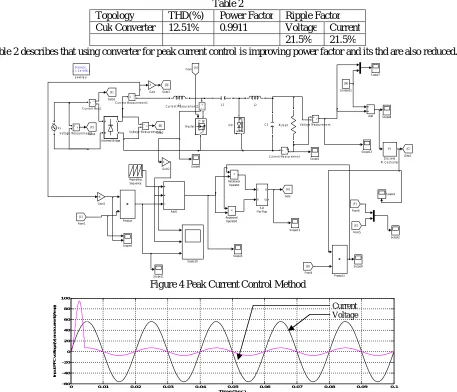
a. Peak Current Control Method Using Cuk Converter
Vol. 5, Issue 4, April 2016
Table 1 Circuits Parameter Used In Simulation
Components / Parameters Values
Input Voltage 56.4 RMS
Inductor
0.26e-3 H
Capacitor
3000e-6 F
Resistor 50 Ohm
Switching frequency 20 kHz
Reference Voltage 100 V
Table1 shows circuits parameters used in simulation i.e. voltage, inductor, capacitor, resistor, frequency Parameters. The circuit diagram of peak current control method using Cuk converter is shown in figure 3. It is in MATLAB software. The value of each component is shown in table. I am using 56.4 RMS in input and it gets step up/down in output. Values of PI controller are set according to circuit. The table shows basic component of circuit diagram.The results of simulation are shown in below.
Table 2
Topology THD(%) Power Factor Ripple Factor
Cuk Converter 12.51% 0.9911 Voltage Current
21.5% 21.5%
Table 2 describes that using converter for peak current control is improving power factor and its thd are also reduced.
Figure 4 Peak Current Control Method Discrete,
Ts = 1e-0 06 s.
p owerg ui
Vs +v
-Voltage Measurement2 v + -Voltage Measurement1 v + -Voltage Measurement A B + -Universal Bridge Sco pe9 Sco pe8 Scope7 Sco pe6 Scop e5 Scop e4 Scope3 Sco pe2 Sco pe13 Scope1 2 Sco pe11 Scope 10 Scope1 S R Q !Q S-R Flip -Flop Repe ating Sequ ence < Relat ional Operator1 > Rel ationa l
Op erator RLload Product1 Prod uct g D S Mosfet L2 L1 [F] Goto 5 [ E] Go to4 [D] Go to3 [B] Goto2 [C] Goto 1 [A] Goto 1 Ga in2 -K-Gain1 3 Gain [F] From 6 [E] From 5 [B] From3 [C] From 1 [ A] From m a k Dm PI Discrete PI Controller i + -Current Measurement2 i + -Current Measurement1 i + -Current Measurement i +
-C urrent Mea1
100 Co nstant 1
C2 C1
Add1
Add
0 0.01 0.02 0.03 0.04 0.05 0.06 0.07 0.08 0.09 0.1
Figure 6 DC Output Voltage
b. Average Current Control Method Using Cuk Converter
The circuit diagram of average current control method using cuk converter. It is also in MATLAB software. The value of each component is shown in table 1.
The results of simulation are shown as below.
Table 3
Topology THD
(%)
Power Factor Ripple Factor
Current Control Method
38.42% 0.9993 Voltage Current
8.7% 8.5%
Table 3 shows values of average current control technique for cuk converter is also improving power factor and also reduces THD.
Figure 7 Average Current Control Method
Figure 8 Input PFC Of Voltage And Current
0 0.1 0.2 0.3 0.4 0.5 0.6 0.7 0.8 0.9 1
0 10 20 30 40 50 60 70 80 90 100
Tim e (Se c)
D C O u tp u t V o lt a g e Discrete , Ts = 1e-006 s.
powe rgui Vs v + -Voltage Measurement2 v + -Voltage Measurement1 v + -Voltage Measurement A B + -Universal Bridge Scope8 Scope7 Scope6 Scope5 Scope4 Scope3 Scope2 Scope1 Repeating Sequence >= Relational Operator RLload Product PID PID Controller3 PID PID Controller2 g D S Mosfet L2 L1 [Iref] Goto7 [Vref] Goto6 [Iin] Goto5 [Vs] Goto4 [pi] Goto3 [Gate] Goto2 [Is] Goto1 3 Gain2 -K-Gain1 0.7 Gain [Iin] From4 [Vref] From3 [Vs] From2 [Is] From1 [Gate] From m a k Dm i + -Current Measurement2 i + -Current Measurement1 i + -Current Measurement i + -C urrent Mea1
1 Constant2 100 Constant1 C2 C1 Add
0 0.01 0.02 0.03 0.04 0.05 0.06 0.07 0.08 0.09 0.1
-200 -150 -100 -50 0 50 100 150 200 Time(Sec) In p u t P F C o f v o lt a g e (V ) a n d C u rr e n t( a m p ) Voltage Current
Vol. 5, Issue 4, April 2016
Figure 9 DC Output Voltage
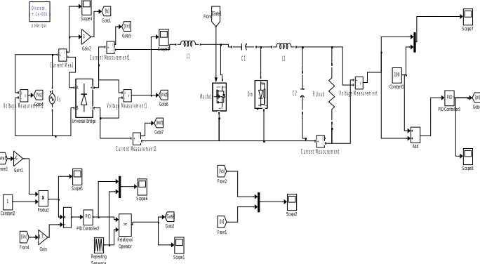
c. Hysteresis Control Method
The circuit diagram of hysteresis current control method using cuk converter. It is also in MATLAB software. The value of each component is shown in table 1.
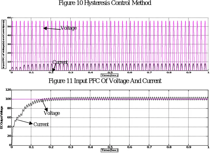
Figure 10 Hysteresis Control Method
Figure 11 Input PFC Of Voltage And Current
Figure 12 DC Output Volatge
0 0.1 0.2 0.3 0.4 0.5 0.6 0.7 0.8 0.9 1
-20 0 20 40 60 80 100 Time(Sec) D C o u tp u t v o lt a g e Discre te, Ts = 1e-006 s.
po we rgui
Vs v + -Voltage Measurement2 v + -Voltage Measurement1 v + -Voltage Measurement A B + -Universal Bridge Scope8 Scope7 Scope6 Scope5 Scope4 Scope3 Scope2 Scope1 Repeating Sequence >= Relational Operator RLload Product PID PID Controller3 PID PID Controller2 g D S Mosfet L2 L1 [Iref] Goto7 [Vref] Goto6 [Iin] Goto5 [Vs] Goto4 [pi] Goto3 [Gate] Goto2 [Is] Goto1 3 Gain2 -K-Gain1 0.7 Gain [Iin] From4 [Vref] From3 [Vs] From2 [Is] From1 [Gate] From m a k Dm i + -Current Measurement2 i + -C urrent Measurement1
i + -Current Measurement i
+
-C urrent Mea1
1 Constant2 100 Constant1 C 2 C 1 Add
0 0.1 0.2 0.3 0.4 0.5 0.6 0.7 0.8 0.9 1
0 10 20 30 40 50 60 Tim e(Sec) In p u t P F C o f V o lt a g e (V ) a n d C u rr e n t( a m p )
0 0.1 0.2 0.3 0.4 0.5 0.6 0.7 0.8 0.9 1
Table 4
Topology THD (%) Power Factor Ripple Factor
Hysteresis Control 3.65% 0.9998 Voltage Current
6.6% 7.00%
Table 4 shows improved power factor nearer o unity and reduced THD using Hysteresis Control by cuk converter topology.
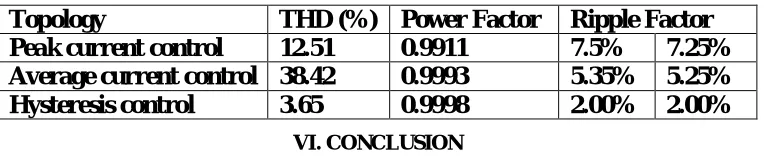
Comparative results of performance parameters of cuk converter topology with various current control strategies incorporated from below table, it can be preferable that hysteresis control technique is most preferable as it affords low THD for supply voltage and improved power factor.
Table 5
Topology
THD (%) Power Factor Ripple Factor
Peak current control
12.51
0.9911
7.5%
7.25%
Average current control 38.42
0.9993
5.35%
5.25%
Hysteresis control
3.65
0.9998
2.00%
2.00%
VI. CONCLUSION
A cuk converter using various topologies has been studied and it is found that proposed topology has improved power factor and supply current, THD and ripple factor. The current control technique for improving power quality for cuk converter has been analyzed. Comparative analysis of peak current, average current and hysteresis has been also carried out in MATLAB Simulink. The simulation obtained show that hysteresis control offers power factor very close to unity and supply current THD is 3.00% compared to other techniques.
REFERENCES
[1] A. A. Fardoun, E. H. Ismail, A. J. Sabzali and M. A. Al- Saffar, “A Comparision Between Three Proposed Bridgeless Cuk Topologies and
Conventional Topologies For Power Factor Correction,” IEEE Transaction on Power Electronics,Vol. 27, no. 7, pp. 3292-3301, July 2012.
[2] M. R. Sahid, A. H. Yatim, and N. D. Muhammad “A bridgeless Cuk PFC converter”, IEEE Applied Power Electronics Colloquium (IAPEC),
pp. 81 – 85, 2011.
[3] Lin, B.-T., Lee, Y.-Sh: ‘Power-factor correction using Cuk converters in discontinuous-capacitor-voltage mode operation’, IEEE Trans. Ind.
Electron., (44), pp. 648–653, 1997, 5,.
[4] Fardoun, A.A.; Ismail, E.H.; Sabzali, A.J.; Al-Saffar M.A., "New Efficient Bridgeless Cuk Rectifiers for PFCApplications," Power
Electronics, IEEE Transactions on , vol.27, no.7, pp.3292, 3301, July 2012.
[5] Ashima Kulshreshtha, Anmol R. Saxena, A. K. Wadhwani, “Average current control of DC-DC Cuk Converters as Power Factor Corrector”,
Int. Journal of Engineering Research and Applications, ISSN : 2248-9622, Vol. 5, Issue 5, pp.56-61,( Part -1) May 2015
[6] Md. Ismail Hossain and Dr. Mohammad Jahangir Alam, “Cuk Topology Based Power Factor Correction and Output Voltage Regulation of
AC-DC Converter”, International Conference on Electrical Engineering and Information & Communication Technology (ICEEICT) 2014
[7] Wang Wei, “A novel bridgeless buck-boost PFC converter” Power Electronics Specialists Conference, IEEE Page(s): 1304– 1308 PESC 2008.
2008.
[8] Muhammad H. Rashid “Power Electronics Handbook 3rd edition devices circuits and application” Elsevier Inc, Burlington USA, 2011
[9] Mr. Damodhar Reddy, K. Pavan Kumar, Goud K. Pradeep Kumar Reddy, “Analysis Of Different Topologies For Active Power Factor
Correction Using DC-DC Converters”, IJATER, 2014.