June 2017
Available online: https://edupediapublications.org/journals/index.php/IJR/ P a g e | 105
Control strategy for 3-phase Inverter with PI based Micro
grid with Induction motor Application
S.�PRIYANKA ASSISTANT PROFFESER
Department of Electrical & Electronics Engineering,
PRINCETON INSTITUTE OF ENGINEERING AND TECHNOLOGY FOR WOMEN, RANGA REDDY (Dt); Telangana, India
Abstract— The increasing presence of single-phase distributed generators and unbalanced loads in the electric power system may lead to unbalance of the three phase voltages, resulting in increased losses and heating. This presents a unified control strategy that enables both islanded and grid-tied operations of three-phase inverter in distributed generation, with no need for switching between two corresponding controllers or critical islanding detection. Intentional islanding describes the condition in which a microgrid or a portion of the power grid, which consists of a load and a distributed generation (DG) system, is isolated from the remainder of the utility system. When the microgrid is cut off from the main grid, each DG inverter system must detect this islanding situation and must switch to a voltage control mode. The control strategy composes of an inner inductor current loop, and a novel voltage loop in the synchronous reference frame. Induction motor is one of the load in grid. The inverter is regulated as a current source just by the inner inductor current loop in grid-tied operation, and the voltage controller is automatically activated to regulate the load voltage upon the occurrence of islanding. The proposed converter applied to induction motor drive application to check the performance speed and torque of induction motor drive.
Index Terms— Unified Power Quality Conditioner, Three Phase Inverter, Distributed generation (DG), islanding, load current, seamless transfer.
I. INTRODUCTION
In contemporary world interconnection of distributed generations (DG) which operate in parallel with electrical power networks, is currently changing the paradigm we are used to live with. Distributed generation is gaining worldwide interest because of environmental issues and rising in energy prices and power plant construction costs. Distributed generations are relatively small and many of them make use of renewable energy such as fuel cells, gas turbines, micro-hydro, wind turbines and photovoltaic. Many DGs use power electronic inverters, instead of rotating generators. The inverters typically have fast current limiting functions for self protection, and may not be damaged by out-of-phase reclosing. The operation of distributed generation will enhance the power quality in power system and this interconnection especially with reverse power flow may lead to some problems like voltage and frequency deviation, harmonics, reliability of the power system and islanding phenomenon. Islanding is one of the most technical concerns associated with the proliferation of distributed generation connected to utility networks. Islanding can be defined as a condition in which a portion of the utility system contains both load and distributed
generation remains energized while being isolated from the remainder of the utility system. Islanding detection is a mandatory feature for grid-connected inverters as specified in international standards and guidelines. Inverters usually operate with current control and unity power factor and employ passive monitoring for islanding detection methods based on locally measured parameters. Under islanding conditions, the magnitude and frequency of the voltage at the point of common coupling (PCC) tend to drift from the rated grid values as a function of the power imbalance (ΔP and ΔQ). As it is known that distribution system does not have any active power generating source and does not receive power in case of a fault in transmission line.
However, with Distributed Generation this presumption is no longer valid. In current practice DG is required to disconnect the utilities from the grid in case of islanding. The main issues about islanding are:1). Safety issues since a portion of the system remains energized while it is not expected.2).Islanded system may be inadequately grounded by the DG interconnection.3).Instantaneous reclosing could cause out of phase in the system.4). Loss of control over voltage and frequency in the system. 5). Excessive transient stresses upon reconnection to the grid. 6). Uncoordinated protection. The strategy of islanding detection is to monitor the DG output parameters for the system and based on the measurements decide whether an islanding situation has occurred from monitoring of these parameters. Islanding detection techniques can be divided into remote and local techniques. A multilevel inverter is a power electronic system that synthesizes a desired output voltage from several levels of dc voltages as inputs. Recently, multilevel power conversion technology has been developing the area of power electronics very rapidly with good potential for further developments. As a result, the most attractive applications of this technology are in the medium to high voltage ranges [3].
Fig.1 Schematic diagram of the DG based on the proposed control strategy.
Its applications are in the field of high-voltage high-power applications such as laminators, mills, conveyors, compressors, large induction motor drives, UPS systems, and static var compensation. Its working principle is based on producing small output voltage steps which results in better
includes more number of switching devices, diodes, and other passive elements. Hence inverter becomes bulky, more control complexity and introduces voltage-imbalance. To solve the above problem, an asymmetric topology H-bridge inverter with three unequal DC sources is used. This topology has the capability of utilizing different DC voltages on the individual H-bridge cells.
A.Passive methods
This method is fast to detect the islanding. But it has large non detection zone and it need special care to set the thresholds for it is parameters. Passive method can classified into: Rate of change of output power, Rate of change of frequency, rate of change of frequency over power, Change of impedance, voltage unbalance, and harmonic distortion
B.Active Methods
Active method tries to overcome the shortcomings of passive methods by introducing perturbations in the inverter output. Active method can detect the islanding even under the perfect match of generation and load, which is not possible in case of the passive detection schemes but it caused degradation of power quality. Active method can be classified into: Reactive power export error detection , Impedance measurement method, Phase (or frequency) shift methods , Active Frequency Drift ,Active Frequency Drift with Positive Feedback Method , Adaptive Logic Phase Shift ,Current injection with positive feedback.
C.Hybrid Methods
Hybrid method based on implementing of two assortment of active and passive method. The active technique is implemented only when the islanding is suspected by the passive technique. It can be classified into: Technique based on voltage and reactive power shift, Technique based on positive feedback and voltage imbalance In current into the utility for mitigating the harmonic component of the grid
current, is presented in [41]. general, once the main grid source supply is lost the DG has to take charge of the remaining network and the connected loads. Passive detection scheme, on the other hand, monitors parameters for detecting the islanding operations of DG: voltage unbalance, frequency, active and reactive power along with total harmonic distortion (THD).
In the hybrid voltage and current mode control, there is a need to switch the controller when the operation mode of DG is changed. During the interval from the occurrence of utility outage and switching the controller to voltage mode, the load voltage is neither fixed by the utility, nor regulated by the DG, and the length of the time interval is determined by the islanding detection process. Therefore, the main issue in this approach is that it makes the quality of the load voltage heavily reliant on the speed and accuracy of the islanding detection method [6]–[10]. Another issue associated with the aforementioned approaches is the waveform quality of the grid current and the load voltage under nonlinear local load. In the grid-tied mode, the output current of DG is generally desired to be pure sinusoidal.
Fig.2 Overall block diagram of the proposed unified control strategy
When the nonlinear local load is fed, the harmonic component of the load current will fully flow into the utility. The voltage mode control is enhanced by controlling the DG to emulate a resistance at the harmonic frequency, and then the harmonic current flowing into utility can be mitigated. This paper proposes a unified control strategy that avoids the aforementioned shortcomings. First, the traditional inductor current loop is employed to control the three-phase inverter in DG to act as a current source with a given reference in the synchronous reference frame (SRF). Second, a novel voltage controller is presented to supply reference for the inner inductor current loop, where a proportional-plus-integral (PI) compensator and a proportional (P) compensator are employed in D-axis and Q-axis, respectively. In the grid-tied operation, the load voltage is dominated by the utility, and the voltage compensator in D-axis is saturated, while the output of the voltage compensator in Q-axis is forced to be
zero by the PLL. Therefore, the reference of the inner current loop cannot regulated by the voltage loop, and the DG is controlled as a current source just by the inner current loop. Moreover, the proposed control strategy, benefiting from just utilizing the current and voltage feedback control, endows a better dynamic performance, compared to the voltage mode control.
II. PROPOSED CONTROL STRATEGY
D.Power Stage
June 2017
Available online: https://edupediapublications.org/journals/index.php/IJR/ P a g e | 107 electrical energy, which is then converted to dc by the
front-end power converter, and the output dc voltage is regulated by it. Therefore, they can be represented by the dc voltage source Vdc in Fig. 1. In the ac side of inverter, the local critical load is connected directly. It should be noted that there are two switches, denoted by Su and Si , respectively, in Fig. 1, and their functions are different [1]-[5]. The inverter transfer switch Si is controlled by the DG, and the utility protection switch Su is governed by the utility. When the utility is normal, both switches Si and Su are ON, and the DG in the grid-tied mode injects power to the utility. When the utility is in fault, the switch Su is tripped by the utility instantly, and then the islanding is formed. After the islanding has been confirmed by the DG with the islanding detection scheme [6]–[10], the switch Si is disconnected, and the DG is transferred from the grid-tied mode to the islanded mode. When the utility is restored, the DG should be resynchronized with the utility first, and then the switch S I is turned ON to connect the DG with the grid .
B. Basic Idea
With the hybrid voltage and current mode control [17]–[40], the inverter is controlled as a current source to generate the reference power PDG+jQDG in the grid-tied mode. And its
output power PDG+jQDG should be the sum of the power
injected to the grid Pg +jQg and the load demand P load + jQ load, which can be expressed as follows by assuming that the load is represented as a parallel RLC circuit:
(1)
(2)
In (1) and (2), Vman dω represent the amplitude and frequency of the load voltage, respectively. When the nonlinear local load is fed, it can still be equivalent to the parallel RLC circuit by just taking account of the fundamental component. During the time interval from the instant of islanding happening to the moment of switching the control system to voltage mode control, the load voltage is neither fixed by the utility nor regulated by the inverter, so the load voltage may drift from the normal range [6]. And this phenomenon can be explained as below by the power relationship. During this time interval, the inverter is still controlled as a current source, and its output power is kept almost unchanged. However, the power injected to utility decreases to zero rapidly, and then the power consumed by the load will be imposed to the output power of DG. If both active power Pg and reactive power Qg injected into the grid are positive in the grid-tied mode, then P load and Q load will increase after the islanding happens, and the amplitude and frequency of the load voltage will rise and drop, respectively, according to (1) and (2) With the previous analysis, if the output power of inverter PDG+jQDG
could be regulated to match the load demand by changing the current reference before the islanding is confirmed, the load voltage excursion will be mitigated. And this basic idea is utilized in this paper. In the proposed control strategy, the output power of the inverter is always controlled by
regulating the three-phase inductor current iLabc, while the
magnitude and frequency of the load voltage vCabc are
monitored. When the islanding happens, the magnitude and frequency of the load voltage may drift from the normal range, and then they are controlled to recover to the normal range automatically by regulating the output power of the inverter.
C. Control Scheme
Fig. 2 describes the overall block diagram for the proposed unified control strategy, where the inductor current iLabc
,the utility voltage vg abc, the load voltage vCabc, and the
load current iLLabc are sensed. And the three-phase inverter
is controlled in the SRF, in which, three phase variable will be represented by dc quantity. The control diagram is mainly composed by the inductor current loop, the PLL, and the current reference generation module. In the inductor current loop, the PI compensator is employed in both D- and Q-axes, and a decoupling of the cross coupling denoted byω0Lf/k PWM is implemented in order to mitigate the couplings due to the inductor. The output of the inner current loop dd q , together with the decoupling of the capacitor voltage denoted by 1/k PWM, sets the reference for the standard space vector modulation that controls the switches of the three-phase inverter. It should be noted that k PWM denotes the voltage gain of the inverter, which equals to half of the dc voltage in this paper.
Fig.3 Block diagram of the current reference generation module
The block diagram of the proposed current reference generation module is shown in Fig. 3, which provides the current reference for the inner current loop in both grid-tied and islanded modes. In this module, it can be found that an unsymmetrical structure is used in D- and Q-axes. The PI compensator is adopted in D-axes, while the P compensator is employed in Q-axis. Besides, an extra limiter is added in the D-axis. Moreover, the load current feed forward is implemented by adding the load current iLL dq to the final
inductor current reference iLref dq. The benefit brought by
the unique structure in Fig. 3 can be represented by two parts: 1) seamless transfer capability without critical islanding detection; and 2) power quality improvement in both grid-tied and islanded operations. The current reference iLre dq composes of four parts in D-and Q-axes respectively: 1) the output of voltage controller iref dq; 2) the
grid current reference Igref dq; 3) the load current iLLdq;
and 4) the current flowing through the filter capacitor Cf.
In the grid-tied mode, the load voltage vC dq is clamped by
the utility. The current reference is irrelevant to the load voltage, due to the saturation of the PI compensator in D-axis, and the output of the P compensator being zero inQ-axis, and thus, the inverter operates as a current source. Upon occurrence of islanding, the e voltage by regulating the current reference, and the inverter acts as a voltage source to supply stable voltage to the local load; this relieves the need for switching between different control architectures. Another distinguished function of the current reference generation module is the load current feed forward. The sensed load current is added as a part of the inductor current reference iLref dq to compensate the harmonic component in the grid current under nonlinear local load. In the islanded mode, the load current feed forward operates still, and the disturbance from the load current, caused by the nonlinear load, can be suppressed by the fast inner inductor current loop, and thus, the quality of the load voltage is improved [9]-[13].
The inductor current control in Fig. 2 was proposed in previous publications for grid-tied operation of DG, and the motivation of this paper is to propose a unified control strategy for DG in both grid-tied and islanded modes, which is represented by the current reference generation module in Fig. 3. The contribution of this module can be summarized in two aspects. First, by introducing PI compensator and P compensator in D-axis and Q-axis respectively, the voltage controller is in activated in the grid-tied mode and can be automatically activated upon occurrence of islanding.
III. OPERATING PRINCIPLE OF DG
The operation principle of DG with the proposed unified control strategy will be illustrated in detail in this section, and there are in total four states for the DG, including the grid-tied mode, transition from the grid-tied mode to the islanded mode, the islanded mode, and transition from the islanded mode to the grid-tied mode.
A. Grid-Tied Mode
When the utility is normal, the DG is controlled as a current source to supply given active and reactive power by the inductor current loop, and the active and reactive power can
be given by the current reference of D- and Q-axis independently. First, the phase angle of the utility voltage is obtained by the PLL, which consists of a Park transformation expressed by (3), a PI compensator, a limiter, and an integrator
(3) Second, the filter inductor current, which has been transformed into SRF by the Park transformation, is fed back and compared with the inductor current reference iLref dq, and the inductor current is regulated to track the reference iLref dq by the PI compensator GI. The reference of the inductor current loop iLref dq seems complex and it is explained as below. It is assumed that the utility is stiff, and the three-phase utility voltage can be expressed as
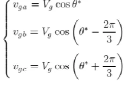
(4) Where Vg is the magnitude of the grid voltage, and θ∗ is the actual phase angle. By the Park transformation, the utility voltage is transformed into the SRF, which is shown as
(5) vgq is regulated to zero by the PLL, so vgd equals the magnitude of the utility voltage Vg. As the filter capacitor voltage equals the utility voltage in the gird-tied mode,vCd equals the magnitude of the utility voltage Vg, and vCq equals zero, too. In the D-axis, the inductor current reference iLref d can be expressed by (6) according to Fig. 3
(6) The first part is the output of the limiter. It is assumed that the given voltage reference Vmaxis larger than the magnitude of the utility voltage vCd in steady state, so the PI compensator, denoted by GVD n the following part, will saturate, and the limiter outputs its upper value Igref d. The second part is the load current of D-axis LLd, which is determined by the characteristic of the local load. The third part is the proportional part −ω0Cf ·vCq, where ω0 is the rated angle frequency, and Cf is the capacitance of the filter capacitor. It is fixed as vCq depends on the utility voltage. Consequently, the current reference iLref d is imposed by the given reference Igref d and the load current iLLd, and is independent of the load voltage.
In theQ-axis, the inductor current reference i Lref q consists of four parts as
June 2017
Available online: https://edupediapublications.org/journals/index.php/IJR/ P a g e | 109 output of GVQ which is zero as the vCq has been regulated
to zero by the PLL. The second part is the given current reference Igref q, and the third part represents the load current in Q-axis. The final part is the proportional part−ω0Cf ·vCd, which is fixed since vCd depends on the utility voltage. Therefore, the current reference ILr efq cannot be influenced by the external voltage loop and is determined by the given reference Igref q and the load current iLLq.
Fig.4 Simplified block diagram of the unified control strategy when DG operates in the grid-tied mode
B. Transition from the Grid-Tied Mode
To the Islanded Mode When the utility switch Suspense, the islanding happens, and the amplitude and frequency of the load voltage will drift due to the active and reactive power mismatch between the DG and the load demand. The transition, shown in Fig. 5, can be divided into two time interval. The first time intervals is from the instant of turning off Suto the instant of turning off S i when islanding is confirmed. The second time interval begins from the instant of turning off inverter switch Si During the first time interval, the utility voltage vg abcis still the same with the load voltage vCabc as the switch Si is in ON state. As the dynamic of the inductor current loop and the voltage loop is much faster than the PLL [52], while the load voltage and current are varying dramatically, the angle frequency of the load voltage can be considered to be not varied. The dynamic process in this time interval can be described by Fig. 6, and it is illustrated later.
Fig.5 Operation sequence during the transition from the grid-tied mode to the islanded mode
Fig.6 Transient process of the voltage and current when the islanding happens
In the grid-tied mode, it is assumed that the DG injects active and reactive power into the utility, which can be expressed by (8) and (9), and that the local critical load, shown in (10), represented by a series connected RLC circuit with the lagging power factor
(8)
(9)
(10) When islanding happens ,igd will decrease from positive to zero, and igq will increase from negative to zero. At the same time, the load current will vary in the opposite direction. The load voltage in D- andQ-axes is shown by (11) and (12), and each of them consists of two terms. It can be found that the load voltage in D-axis vCd will increase as both terms increase.
However, the trend of the load voltage in Q-axis vCq is uncertain because the first term decreases and the second term increases,and it is not concerned for a while
(11)
(12) With the increase of the load voltage in D-axis vCd, when it reaches and exceeds Vmax, the input of the PI compensator GVD will become negative, so its output will decrease. Then, the output of limiter will not imposed to Igref dany longer, and the current reference iLref dwill drop. With the regulation of the inductor current loop, the load current in D-axis iLLd will decrease. As a result, the load voltage inD-axis vCd will drop and recover to Vmax. After iLLd has
interval, the load voltage in D-axis vCdw ill be increased to and fixed at Vmax, and the angle frequency of the load voltage ωwill drop. If it is higher than the lower value of the limiter ωmin, the PLL can still operate normally, and the load voltage in Q-axis vCq will be zero. Otherwise, if it is fixed at ωmin, the load voltage inQ-axis vCq will be negative. As the absolute values of vCd and vCq,at least the one of vCd, are raised, the magnitude of the load voltage will increase finally.
The variation of the amplitude and frequency in the load voltage can also be explained by the power relationship mentioned before. When the islanding happens, the local load must absorb the extra power injected to the grid, as the output power of inverter is not changed instantaneously. According to (1), the magnitude of the load voltage Vm will rise with the increase of P load. At the same time, the angle frequency ω should drop, in order to consume more reactive power with (2). Therefore, the result through the power relationship coincides with the previous analysis. The second time interval of the transition begins from the instant when the switch S i is open after the islanding has been confirmed by the islanding detection method. If the switch Si opens, the load voltage vCabc is independent with the grid voltage vgabc. At the same time, vgabc will reduce to zero theoretically as the switch Su has opened. Then, the input of the compensator GPLL becomes zero and the angle frequency is invariable and fixed to the value at the end of the first interval. Under this circumstance, vCdq is regulated by the voltage loop, and the inverter is controlled to be a voltage source. With the previous analysis, it can be concluded that the drift of the amplitude and frequency in the load voltage is restricted in the given range when islanding happens. And the inverter is transferred from the current source operation mode to the voltage source operation mode autonomously. In the hybrid voltage and current mode control [10], the time delay of islanding detection is critical to the drift of the frequency and magnitude in the load voltage, because the drift is worse with the increase of the delay time. However, this phenomenon is avoided in the proposed control strategy.
C. Islanded Mode
In the islanded mode, switching Si and Su are both in OFF state. The PLL cannot track the utility voltage normally, and the angle frequency is fixed. In this situation, the DG is controlled as a voltage source, because voltage compensator GVD and GVQ can regulate the load voltage vCdq. The voltage references in D and Q-axis are Vmax and zero, respectively. And the magnitude of the load voltage equals to Vmax approximately, which will be analyzed in Section IV. Consequently, the control diagram of the three-phase inverter in the islanded mode can be simplified as shown in Fig. 7. In Fig. 7, the load current iLLdq is partial reference of the inductor current loop. So, if there is disturbance in the load current, it will be suppressed quickly by the inductor current loop, and a stiff load voltage can be achieved.
Fig.7 Simplified block diagram of the unified control strategy when DG operates in the islanded mode
D. Transition from the Islanded Mode
To the Grid-Tied Mode If the utility is restored and the utility switch Su is ON, the DG should be connected with utility by turning on switch Si. However, several preparation steps should be performed before turning on switch S First, as soon as utility voltage is restored, the PLL will track the phase of the utility voltage. As a result, the phase angle of the load voltage vCabc will follow the grid voltage vgabc.If the
load voltage vCabc is in phase with the utility voltage, vgd will
equal the magnitude of the utility voltage according to (5). Second, as the magnitude of the load voltage Vmax is larger than the utility voltage magnitude Vg, the voltage reference Vref will be changed to Vg by toggling the selector S from terminals 1 to 2. As a result, the load voltage will equal to the utility voltage in both phase and magnitude. Third, the switch Si is turned on, and the selector S is reset to terminal 1. In this situation, the load voltage will be held by the utility. As the voltage reference Vref equals Vmax, which PI compensator GVD will saturate, and the limiter outputs its upper value Igref d. At the same time, vCq is regulated to
zero by the PLL according to (5), so the output of GVQ will be zero. Consequently, the voltage regulators GVD and GVQ are inactivated, and the DG is controlled as a current source just by the inductor current loop.
IV.MATLAB/MODELING & RESULTS
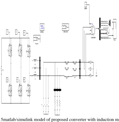
Here simulation is carried out in different cases, in that 1). Proposed Three Phase Three level Inverter Fed Distributed Generation Scheme using Unified Control Scheme. 2). Proposed converter with induction motor drive applications
June 2017
Available online: https://edupediapublications.org/journals/index.php/IJR/ P a g e | 111 Fig.8 Matlab/Simulink Model of Proposed Three Phase Three level Inverter
Fed Distributed Generation Scheme using Unified Control Scheme Fig.8 shows the Matlab/Simulink Model of Proposed Three Phase Three level Inverter Fed Distributed Generation Scheme using Unified Control Scheme using Matlab/Simulink tool.
Fig.9 Simulation waveforms of load voltage vC a , grid current iga, and inductor current iLa when DG is in the grid-tied mode under condition of the step down of the grid current reference from 9 A to 5 A with proposed unified control strategy.
Fig.10 Simulation waveforms of load voltage vC a , grid current iga, and inductor current iLa when DG is transferred from the grid-tied mode to the islanded mode with proposed unified control strategy.
Fig. 11 simulation waveform when DG feeds nonlinear load in islanded mode with load current feed-forward and
Fig. 12 simulation waveform when DG feeds nonlinear load in islanded mode without load current feed-forward
Fig.13 simulation waveforms when DG feeds nonlinear load in the gridtied mode with load current feed-forward
Fig.14 simulation waveforms when DG feeds nonlinear load in the gridtied mode without load current feed-forward
Case 2: Proposed converter with induction motor drive applications
Fig.16 output waveforms of stator current, speed and electromagnetic torque of the induction motor drive
V. CONCLUSION
In this concept PI based control strategy for 3-phase Inverter in Micro grid with Induction motor application is to check the performance of drive. A unified control strategy was proposed for three-phase inverter in DG to operate in both islanded and grid-tied modes, with no need for switching between two different control architectures or critical islanding detection. It is inactivated in the grid-tied mode, and the DG operates as a current source with fast dynamic performance. Upon the utility outage, the voltage controller can automatically be activated to regulate the load voltage. Moreover, a novel load current feed forward was proposed, and it can improve the waveform quality of both the grid current in the grid-tied mode and the load voltage in the islanded mode. A advanced control strategy was proposed for three-phase inverter in DG to operate in both islanded and grid-tied modes, with no need for switching between two different control architectures or critical islanding detection. The above all simulation results are verified through Matlab/simulink software
REFERENCES
[1] R. C. Dugan and T. E. McDermott, “Distributed generation,” IEEE Ind. Appl. Mag., vol. 8, no. 2, pp. 19–25, Mar./Apr. 2002.
[2] R. H. Lasseter, “Microgrids and distributed generation,” J. Energy Eng., vol. 133, no. 3, pp. 144–149, Sep. 2007.
[3] C. Mozina, “Impact of green power distributed generation,” IEEE Ind. Appl. Mag., vol. 16, no. 4, pp. 55–62, Jul./Aug. 2010.
[4] IEEE Recommended Practice for Utility Interface of Photovoltaic(PV) Systems, IEEE Standard 929-2000, 2000.
[5] IEEE Standard for Interconnecting Distributed Resources with Electric Power Systems, IEEE Standard 1547-2003, 2003.
[6] J. Stevens, R. Bonn, J. Ginn, and S. Gonzalez, Development and Testing of an Approach to Anti-Islanding in Utility-Interconnected Photovoltaic Systems. Livermore, CA, USA: Sandia National Laboratories, 2000.
[7] A. M. Massoud, K. H. Ahmed, S. J. Finney, and B. W. Williams, “Harmonic distortion based island detection technique for inverter-based distributed generation,” IET Renewable Power Gener., vol. 3, no. 4, pp. 493– 507, Dec. 2009.
[8] T. Thacker, R. Burgos, F. Wang, and D. Boroyevich, “Single-phase islanding detection based on phase-locked loop stability,” inProc. 1st IEEE Energy Convers. Congr. Expo., San Jose, CA, USA, 2009, pp. 3371–3377. [9] S.-K. Kim, J.-H. Jeon, J.-B. Ahn, B. Lee, and S.-H. Kwon, “Frequency shift acceleration control for anti-islanding of a distributed-generation inverter,” IEEE Trans. Ind. Electron., vol. 57, no. 2, pp. 494–504, Feb. 2010.
[10] A. Yafaoui, B. Wu, and S. Kouro, “Improved active frequency drift anti islanding detection method for grid connected photovoltaic systems,” IEEE Trans. Power Electron., vol. 27, no. 5, pp. 2367–2375, May 2012.
[11] J. M. Guerrero, L. Hang, and J. Uceda, “Control of distributed uninterruptible power supply systems,” IEEE Trans. Ind. Electron., vol. 55, no. 8, pp. 2845–2859, Aug. 2008.
[12] M. C. Chandorkar, D. M. Divan, and R. Adapa, “Control of parallel connected inverters in standalone AC supply systems, ”IEEE Trans. Ind. Appl., vol. 29, no. 1, pp. 136–143, Jan./Feb. 1993.
[13] Y. Li, D. M. Vilathgamuwa, and P. C. Loh, “Design, analysis, and realtime testing of a controller for multibus microgrid system,” IEEE Trans. Power Electron., vol. 19, no. 5, pp. 1195–1204, Sep. 2004.