Kammula.Jyothi
M.Tech, E.C.E Department
A.K.R.G College of Engineering &
Technology
Nallajerla, A.P. India
A.Vasanth Roy
Assistant Professor, E.C.E Department A.K.R.G College of Engineering & Technology
Nallajerla, A.P. India
ABSTRACT: This system makes protection against soft errors as a requirement for many
applications in this portable world.
Communications and signal processing systems have no exceptions to this trend. For some of the
applications, brilliant option is to use
algorithmic based fault tolerance (ABFT) techniques that are helpful to exploit the
algorithmic properties for detecting and
correcting the errors. Soft errors are responsible for a reliable threat to modern electronic circuits.
Signal processing and communication
applications are good enough to use ABFT. One of the best examples is fast Fourier transforms (FFTs) that are the basic building blocks in many systems. Many protection schemes have been proposed to detect and correct errors in FFTs. Among these, probably the uses of the Parseval or sum of squares check is the most widely known and used techniques. In these modern communication systems, it is most common to find several blocks operating in parallel. Recently, a technique that exploits this fact to implement fault tolerance on parallel filters has been proposed. This technique is first applied to save FFTs. Then, two schemes were implemented for the protection that combines the use of error correction codes and Parseval checks are evaluated. The results show that the proposed schemes can further reduce the implementation cost of protection. The proposed architecture of this paper analysis the logic size, area and reduction of power consumption using Xilinx.
I.INTRODUCTION
The difficulty has been automatically corporate into the devices and systems that are implemented by these ICs. While the number of components that can be integrated on a chip is increasing, the chip itself is becoming responsible for increasing variety of failures and damages ranging from internal opens and shorts for encapsulation and bonding failures. The
complexity of the ICs and digital systems, and
accepting that their complex design and construction are susceptible to the inherent fallibility of those who design and construct, and also taking into account the limitations imposed by the technology used, it would be surprising that if any modern computing system provides its intended service with ultra-high reliability. It is not sufficient just to design and manufacture complex ICs and digital systems, but system designers and manufacturers must also present measures to improve the reliability of these complex devices and systems.
The drastically increase in the reliability requirements of digital systems force the designers to attempt methods to achieve high reliability. As an example the reliability for the Saturn V launch computer (1964) was only 0.99
for 250 hours, in comparison to the late 1970s
FTMP and SIFT computers with reliability
requirements of 10 -91.2 - General Methods of
By taking this approach designers and
manufacturers try to prevent system failure by
ensuring that all possible causes of unreliability
have been removed from the system before the
system is put into service. Fault prevention has two aspects, namely, fault avoidance, and fault removal. Fault avoidance is concerned with
design methodologies and the selection
techniques which are used to avoid the introduction of faults during the design and manufacturing of a system. The use of reliable components is an example of fault avoidance. Fault removal is concerned with checking the implementation of a system and removing those faults which are exposed.
Design for Testability (DFT) which concerns the improvement of the controllability and the observability of VLSI circuits to ease testing of these devices has been very successful, but even under this technique testing of VLSI devices is a
serious problem for the designers and
manufacturers of these devices. In many ways, testing a very large scale integrated circuit is more difficult than designing it. It is both possible and likely that a large integrated circuit will contain embedded
For complex circuits, exhaustive testing
becomes unrealistic. For instance, an exhaustive test of the 8080 microcomputer, only modestly complicated by today's standards, would take over 10 to 20 years, at one million tests or a microprocessor such as Motorola 68000 would
take many years of CPU time to test
exhaustively. Thus one may conclude that the primary stumbling blocks in VLSI circuit development are therefore testing of the devices, not design and fabrication. The problem of testing VLSI devices is aggravated by the shortage of test engineers and the high costs of testing, in addition to the difficulties of developing programmers that control the Automated Test Equipment.
However, despite the adoption of fault prevention techniques, faults will occur during
the operation of systems. So when operation
without failure is required despite the presence of faults, the adoption of the above strategies
alone in general is insufficient. There is also an
upper limit for improvement of component or
system reliability due to design methodology, cost limitations, and available manufacturing techniques. Indeed this is the most important reason behind the implementation of designs taking another approach called fault-tolerance.
II.LITERATURE SURVEY
Fault-tolerance is incorporated in a system by adding redundancy (i.e. a system or a component will be replicated many times). The redundancy can be in the form of software, hardware, or a combination of both. To obtain the correct output of a system designed to tolerate failures, the following blocks are generally used.
I) a voting mechanism to vote on the outputs of the replicated modules or components.
II) A disagreement detection circuit to detect any failures occurring during the operation of the system.
III) A switching mechanism to take measures for reconfiguration of the system when failures occur.
This research discusses the above compartments in detail and develops three new fault-tolerant designs to improve the overall system reliability. This research discusses the above compartments in detail and develops three new fault-tolerant designs to improve the overall system reliability. The first design concentrates on the number of gates used in the switching mechanism. As a result a switching circuit is developed which use fewer gates than other similar designs proposed
by others. In the second design, the
the other switch components. This feature has a beneficial effect for reliability improvement. The structure of the switch in the third design is such that it has the same features as in the second design, in addition, it can tolerate more failures than other techniques including the above schemes and thus a better reliability improvement can be achieved by this technique. As the voting component in any fault-tolerant design is the most critical component, an approach will be presented in this work to implement this component as simply as possible. To be able to implement a highly reliable voter, a modular structure is used to minimize the chip area as well as using as few transistors as possible. A new reliability model has been developed and used in an extensive comparison of fault-tolerant techniques (including the new designs).
The reliability improvement made by the designs is also shown. The last part of this research involves the initial development of an expert system which can be used as part of a CAD tool. The expert system will use the knowledge resulting from the comparative study to advice on the fault-tolerant technique that best suits a particular application.
III.EXISTING SYSTEM
Signal processing and communications circuits are well suited for ABFT as they have regular structures and many algorithmic properties. Over the years, many ABFT techniques have been proposed to protect the basic blocks that are commonly used in those circuits. Several works have considered the protection of digital filters. For example, the use of replication using reduced precision copies of the filter has been proposed as an alternative to TMR but with a lower cost. The knowledge of the distribution of the filter output has also been recently exploited to detect and correct errors with lower overheads. The protection of fast Fourier transforms (FFTs) has also been widely studied.
IV.PROPOSED SYSTEM
The rapidly increasing application of computers to areas where the loss of real-time computing power could be catastrophic has brought with it the need for very high reliability. For example process control systems in big plants, control systems in nuclear power stations, or systems which undertake patients' monitoring in care units and the like, should be operational at all times, and must operate continuously without interruption . This means that a failure must be diagnosed, and appropriate measures should be taken to repair or reconfigure the system within a fraction of a second. Therefore techniques should be designed developed and applied to minimize or even eliminate service interruptions of the system. In another words appropriate techniques should be used to increase the reliability of the system. There are generally two approaches to the improvement of reliability of computing systems. The first approach is called fault-prevention (fault intolerance), and the second one is fault-tolerance. In the next section we briefly describe the fault avoidance approach. Then in the following sections the fault-tolerance approach will be reviewed. Fault – prevention
practice however it is impossible to design and develop a system in which there is a guarantee that no failure will occur. During its manufacturing and operation time, a component or element may fail which may cause the entire system to fail (hence the name fault intolerance).There are many cases in which fault prevention alone cannot meet system design specifications. In these cases fault-tolerance techniques should be used. In the fault tolerance approach, faults are expected to occur during the operation of the system, but by using redundancy, the faults will be masked or the faulty units will be replaced by good units automatically (reconfiguration) without any interruption in the system operation: the system can continue to function correctly in spite of fault presence.
Fault Tolerance
Fault-tolerance is defined as the ability to
produce correct results even in the presence of faults, [Av67] [GoLeSh66] [GrMiRo62]. Fault-tolerance is not a replacement of fault-prevention approach but a complement to it. Research activities in the area of fault-tolerant design has increased recently due to the following factors which have had a major impact on the design of these systems.
Error is a condition when the output information does not match with the input information. During transmission, digital signals suffer from noise that can introduce errors in the binary bits travelling from one system to other. That means a 0 bit may change to 1 or a 1 bit may change to 0.
The proposed techniques provide new
alternatives to protect parallel FFTs that can be more efficient than protecting each of the FFTs independently. The proposed schemes have been evaluated using FPGA implementations to assess the protection overhead. The results show that by combining the use of ECCs and Parseval checks, the protection overhead can be reduced
compared with the use of only ECCs as proposed Fault injection experiments have also been conducted to verify the ability of the implementations to detect and correct errors. The rest of this brief is organized as follows. Presents the two proposed schemes. In the implementation overheads and fault tolerance of the schemes are evaluated. Finally, the conclusions are drawn
Fig. 1. Parallel FFT protection using ECCs.
The starting point for our work is the protection scheme based on the use of ECCs that was
presented in for digital filters
.
In this example, asimple single error correction Hamming code is used. The original system consists of four FFT modules and three redundant modules is added to detect and correct errors.
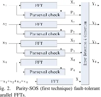
Fig. 2. Parity-SOS (first technique) fault-tolerant parallel FFTs.
used to check linear combinations of the outputs. For example, the input to the first redundant module is
x5 = x1 + x2 + x3 (1)
and since the DFT is a linear operation, its
output z5 can be used to check that
z5 = z1 + z2 + z3. (2)
This will be denoted as c1 check. The same
reasoning applies to the other two redundant
modules that will provide checks c2 and c3.
Based on the differences observed on each of the checks, the module on which the error has occurred can be determined. The different patterns and the corresponding errors are summarized in Table I. Once the module in error is known, the error can be corrected by reconstructing its output using the remaining
modules. For example, for an error affecting z1,
this can be done as follows:
z1c[n] = z5[n] − z2[n] − z3[n]. (3)
Similar correction equations can be used to correct errors on the other modules. More advanced ECCs can be used to correct errors on multiple modules if that is needed in a given application.
The overhead of this technique, as discussed is lower than TMR as the number of redundant FFTs is related to the logarithm of the number of original FFTs. For example, to protect four FFTs, three redundant FFTs are needed, but to protect eleven, the number of redundant FFTs in only four. This shows how the overhead decreases with the number of FFTs.
In Section I, it has been mentioned that over the years, many techniques have been proposed to protect the FFT. One of them is the Sum of Squares (SOSs) check that can be used to detect errors. The SOS check is based on the Parseval
theorem that states that the SOSs of the inputs to the FFT are equal to the SOSs of the outputs of the FFT except for a scaling factor. This relationship can be used to detect errors with low overhead as one multiplication is needed for each input or output sample (two multiplications and adders for SOS per sample). For parallel FFTs, the SOS check can be combined with the ECC approach to reduce the protection overhead. Since the SOS check can only detect errors, the ECC part should be able to implement the correction. This can be done using the equivalent of a simple parity bit for all the FFTs. In addition, the SOS check is used on each FFT to detect errors. When an error is detected, the output of the parity FFT can be used to correct the error. This is better explained with an example. In, the first proposed scheme is illustrated for the case of four parallel FFTs. A redundant (the parity) FFT is added that has the sum of the inputs to the original FFTs as input. An SOS check is also added to each original
FFT. In case an error is detected (using P1, P2,
P3, P4), the correction can be done by
recomputing the FFT in error using the output of
the parity FFT (X) and the rest of the FFT
outputs. For example, if an error occurs in the first FFT, P1 will be set and the error can be corrected by doing
X1c = X − X2 − X3 − X4. (4)
parity- SOS scheme is to reduce the number of SOS checks needed. The error location process is the same as for the ECC scheme in Fig. 1 and correction is as in the parity-SOS scheme. In the following, this scheme will be referred to as
parity-SOS-ECC (or second proposed
technique).The overheads of the two proposed schemes can be initially estimated using the number of additional FFTs and SOS check blocks needed. This information is summarized in Table II for a set of k original FFT modules
assuming k is a power of two. It can be observed
that the two proposed schemes reduce the number of additional FFTs to just one. In addition, the second technique also reduces the number of SOS checks. In Section III, a detailed evaluation for an FPGA implementation is discussed to illustrate the relative overheads of the proposed techniques. In all the techniques discussed, soft errors can also affect the elements added for protection. For the ECC technique, the protection of these elements was discussed In the case of the redundant or parity FFTs, an error will have no effect as it will not propagate to the data outputs and will not trigger a correction. In the case of SOS checks, an error will trigger a correction when actually there is no error on the FFT. This will cause an unnecessary correction but will also produce the correct result. Finally, errors on the detection and correction blocks in Figs. 2 and 3 can propagate errors to the outputs. In our implementations, those blocks are protected with TMR. The same applies for the adders used to compute the inputs to the redundant FFTs in Fig. 1 or to the SOS checks. The triplication of these blocks has a small impact on circuit complexity as they are much simpler than the FFT computations.
A final observation is that the ECC scheme can detect all errors that exceed a given threshold (given by the quantization used to implement the FFTs). On the other hand, the SOS check detects
most errors but does not guarantee the detection of all errors. Therefore, to compare the three techniques for a given implementation, fault injection experiments should be done to determine the percentage of errors that are actually corrected. This means that an evaluation has to be done both in terms of overhead and error coverage.
Fig.3 Parity SOS (second technique) fault tolerant parallel FFT
TABLE1
ERROR LOCATION IN HAMMING CODES
V.EVALUATION
The results show that all techniques have a cost
factor of <2. This demonstrates that the
than TMR. The parity-SOS-ECC technique has the lowest resource use in all cases and, therefore, is the best option to minimize the implementation cost. On the other hand, the parity-SOS scheme needs less resources than the ECC scheme when the number of FFTs but more when the number of FFTs is 11. This can be explained as in the ECC scheme, the number of additional FFTs grows logarithmically with the number of FFTs, while in the parity-SOS technique, the number of SOS checks grows linearly. This means that as the number of FFTs to protect increases, the ECC scheme becomes more competitive. For the parity-SOS-ECC scheme, the number of SOS checks also grows logarithmically and they are simpler to implement than FFTs. Therefore, it remains more competitive than the ECC scheme regardless of the number of FFTs protected. To better illustrate this phenomenon, the number of slices required for the different schemes and number of FFTs is plotted in Fig. 6. It can be observed that eight is the value for which parity-SOS and ECC have almost the same cost. For larger values, the ECC scheme outperforms the parity-SOS technique in our implementation.
As a summary, the results show that the parity-SOS scheme outperforms only the ECC scheme for small number of parallel FFTs, and the parity-SOS-ECC scheme always provides the best results. As mentioned before, a key aspect of any fault tolerant scheme is to validate that it can effectively correct errors. To that end, fault injection experiments have been done on the two proposed schemes and the ECC only scheme. In each simulation run, one error is inserted to mimic the behavior of soft errors that occur in isolation. In particular, 20 000 errors have been randomly injected on the registers for the Fourier coefficients and on the RAMs for the results of each stage of the FFT calculation, respectively. For ECC protected parallel FFTs, a tolerance level of 1 is used for the equation
checks. All faults that introduce errors out of range of [−1, 1] were detected and corrected, which is the same as that reported for parallel FIR filters. For the parity-SOS and parity-SOS-ECC schemes, the fault coverage is determined
by the tolerance level τ used in the Parseval
check (the absolute difference between the input power and the output power). In the
experiments, we have set τ = 1, and the fault
coverage is ∼99.9%, which is similar to the
results reported. This means that approximately 1 out of 1000 errors will not be corrected. Since soft errors are rare events, the residual error rate will be very low and, therefore, acceptable for many communication and signal processing applications.
The two proposed schemes and the ECC scheme presented in have been implemented on an FPGA and evaluated both in terms of overhead and error coverage. A four-point decimation-in-frequency FFT core is used to compute the FFT iteratively. This core has been developed to implement MIMO-OFDM for wireless systems.. The number of FFT points is programmable and the rotation coefficients are calculated on-line for each stage and stored in registers. For the evaluation, a 1024 points FFT is configured with five stages calculation (log41024 = 5), so in total
5∗1024 = 5120 cycles are needed to calculate
function of the number of parallel FFTs in the original system. The error detection and
correction blocks are implemented as
multiplexers that select the correct output depending on the error pattern detected. As mentioned before, these blocks are tripled to ensure that errors that affect them do not corrupt the final outputs. The FFT and the different protection techniques have been implemented using Verilog. Then, the design has been mapped to a Virtex-4 xc4vlx80 FPGA setting the maximum effort on minimizing the use of resources. The results obtained are summarized in Tables. The first table provides the resources needed to implement a single FFT and an SOS check. The results show that the FFT is more complex than the SOS check as expected. The difference will be much larger when a fully parallel FFT implementation is used show the results when different number of parallel FFTs are protected. The objective is to illustrate how the relative overheads of the different techniques vary with the number of parallel FFTs. In parentheses, the cost relative to an unprotected implementation is also provided.
VI.RESULTS
VII.CONCLUTION
The results show that the proposed schemes can further reduce the implementation cost of protection. The proposed architecture of this paper analysis the logic size, area and reduction of power consumption using Xilinx. This technique is first applied to save FFTs. Then, two schemes were implemented for the protection that combines the use of error correction codes and Parseval checks are evaluated.
N. Kanekawa, E. H. Ibe, T. Suga, and Y.
Uematsu, Dependability in Electronic Systems:
Mitigation of Hardware Failures, Soft Errors, and Electro-Magnetic Disturbances. New York, NY, USA: Springer-Verlag,2010.
[2] R. Baumann, “Soft errors in advanced
computer systems,” IEEE Des. Test Comput.,
vol. 22, no. 3, pp. 258–266, May/Jun. 2005. [3] M. Nicolaidis, “Design for soft error
mitigation,” IEEE Trans. Device Mater. Rel.,
vol. 5, no. 3, pp. 405–418, Sep. 2005.
[4] A. L. N. Reddy and P. Banerjee, “Algorithm based fault detection for signal processing
applications,” IEEE Trans. Comput., vol. 39, no.
10, pp. 1304–1308, Oct. 1990.
[5] T. Hitana and A. K. Deb, “Bridging concurrent and non-concurrent error detection in
FIR filters,” in Proc. Norchip Conf., Nov. 2004,
pp. 75–78.
[6] S. Pontarelli, G. C. Cardarilli, M. Re, and A. Salsano, “Totally fault tolerant RNS based FIR
filters,” in Proc. 14th IEEE Int. On-Line Test
Symp. (IOLTS), Jul. 2008, pp. 192–194.
[7] B. Shim and N. R. Shanbhag, “Energy efficient soft error-tolerant digital signal
processing,” IEEE Trans. Very Large Scale
Integr. (VLSI) Syst., vol. 14, no. 4, pp. 336–348, Apr. 2006.
[8] E. P. Kim and N. R. Shanbhag, “Soft N
modular redundancy,” IEEE Trans. Comput.,
vol. 61, no. 3, pp. 323–336, Mar. 2012.
[9] J. Y. Jou and J. A. Abraham, “Fault-tolerant
FFT networks,” IEEE Trans. Comput., vol. 37,
no. 5, pp. 548–561, May 1988.
[10] S.-J. Wang and N. K. Jha,
“Algorithm-based fault tolerance for FFT networks,” IEEE
Trans. Comput., vol. 43, no. 7, pp. 849–854, Jul. 1994.
[11] P. P. Vaidyanathanm, Multirate Systems
and Filter Banks. Englewood Cliffs, NJ, USA: Prentice-Hall, 1993.
[12] A. Sibille, C. Oestges, and A. Zanella,
MIMO: From Theory to Implementation. San Francisco, CA, USA: Academic, 2010.
[13] G. L. Stüber, J. R. Barry, S. W. McLaughlin, Y. Li, M. A. Ingram, and T. G. Pratt, “Broadband MIMO-OFDM wireless
communications,” Proc. IEEE, vol. 92, no. 2,
pp. 271–294, Feb. 2004.
[14] S. Sesia, I. Toufik, and M. Baker, LTE The
UMTS Long Term Evolution: From Theory to Practice, 2nd ed. New York, NY, USA: Wiley, Jul. 2011.
[15] M. Ergen, Mobile Broadband—Including
WiMAX and LTE. New York, NY, USA: Springer-Verlag, 2009.
[16] P. Reviriego, S. Pontarelli, C. J. Bleakley, and J. A. Maestro, “Area efficient concurrent error detection and correction for parallel filters,” IET Electron. Lett., vol. 48, no. 20, pp. 1258–1260, Sep. 2012.
[17] Z. Gao et al., “Fault tolerant parallel filters
based on error correction codes,” IEEE Trans.
Very Large Scale Integr. (VLSI) Syst., vol. 23, no. 2, pp. 384–387, Feb. 2015.
[18] R. W. Hamming, “Error detecting and error
correcting codes,” Bell Syst. Tech. J., vol. 29,