Design and Simulation of Parallel CRC
Generation Architecture for High Speed
Application
Deepali P. Atrawalkar
1, Manoj D. Bagde
2PG Student [Digital Electronics], Dept. of ECE, G. H. Raisoni Institute of Engineering & Management, Jalgaon,
Maharashtra, India1
Dept. of ECE [Digital Electronics], G. H. Raisoni Institute of Engineering & Management, Jalgaon, Maharashtra,
India2
ABSTRACT: High speed data transmission is the current scenario in networking environment. Cyclic redundancy
check (CRC) is essential method for detecting error when the data is transmitted. With challenging the speed of transmitting data, to synchronize with speed, it’s necessary to increase speed of CRC generation. Starting from the serial architecture identified a recursive formula from which parallel design is derived. For simulation and functional verification we will use ModelSim and AlteraQuartus 2. A cyclic redundancy check (CRC) is an error detecting code commonly used in digital networks and storage devices to detect accidental changes to raw data. This paper is based on pipelined CRC method is designed to achieve high throughput by cascading buffers, which improves the time further.
KEYWORDS: VHDL, CRC, FPGA
I. INTRODUCTION
A cyclic redundancy check (CRC) is an error detecting code commonly used in digital networks and storage devices to detect accidental changes to raw data. Blocks of data entering these systems get a short check value attached, based on the remainder of a polynomial division of their contents. On retrieval the calculation is repeated, and corrective action can be taken against presumed data corruption if the check values do not match. CRCs are so called because the check (data verification) value is a redundancy (it expands the message without adding information) and the algorithm is based on cyclic codes. CRCs are popular because they are simple to implement in binary hardware, easy to analyze mathematically, and particularly good at detecting common errors caused by noise in transmission channels. Because the check value has a fixed length, the function that generates it is occasionally used as a hash function.
CRC is an established technique for detecting errors on serial data communication links and in mass storage devices. A frame check sequence is appended to the message for transmission error detection. Many (high-speed) serial data communication protocols employ CRC including fiber distributed data interface (FDDI) and asynchronous transfer mode (ATM). The common hardware solution for CRC calculation is the linear feedback shift register (LFSR), a simple bit serial architecture for both coding and decoding messages. The bit-serial approach lacks efficiency for processing a parallel data stream, since every n-bit data word needs n clock cycles to calculate the check sum. Digital communication system is used to transport an information bearing signal from the source to a user destination via a communication channel. Cyclic redundancy check is commonly used in data communication and other fields such as data storage and data compression, as a essential method for dealing with data errors.
CRCs are used in applications like CRC-16 BISYNC protocols, CRC32 in Ethernet frame for error detection, CRC8 in ATM, CRC-CCITT in X-25 protocol, disc storage, SDLC, and X MOD.
Fig:- 1: 4 Bit Shift Register
The diagram shows four flip-flops connected to form a input output shift register. At arrival of a clock pulse, data at the D input of each flip-flop is transferred to its Q output. First, the contents of the register can be set to zero by means of the CLEAR line. If 1 is applied to the input of the first flip-flop, then the arrival of the first clock pulse, this 1 is transferred to the output of flip-flop 1 (input of flip-flop 2). After 4 clock pulses 1 will be at the output of flip-flop 4. In this way, a four bit number can be stored in the register. After 4 more clock pulses, this data will be shifted out of the register. The implementation of CRC check generation circuit can be done with the use of linear feedback circuit. Basic methodology for generating Serial CRC is based on the Linear Feedback Shift Register (LFSR). The main operation of Serial CRC is similar as the binary division. Generally binary division is executed by a sequence of shifts and subtractions.
CRC can generate in 2 ways: 1. Serial CRC generation 2. Parallel CRC generation
II. LITERATURE REVIEW
In networking environments, the cyclic redundancy check (CRC) is widely utilized to determine whether errors have been introduced during transmissions over physical links. We focus on the CRC calculation in WLAN where the packet size is huge and hence slow CRC calculation may become bottleneck for communication process[1]. . A Cyclic Redundancy Check (CRC) is the remainder, or residue, of binary division of a potentially long message, by a CRC polynomial[2]. Parallel processing is a very efficient way to increase the throughput rate[3].
The parallel CRC generation deal with 64bit parallel processing based on built in F matrix with order of generator polynomial is 32. This gives CRC with half number of cycles[4]. A fast cyclic redundancy check (CRC) algorithm that performs CRC computation for an arbitrary length of message in parallel. For a given message with any length, the algorithm first chunks the message into blocks, each of which has a fixed size equal to the degree of the generator polynomial[5].
throughput rate. Although parallel processing increases the number of message bits that can be processed in one clock cycle, it can also lead to a long critical path (CP)[8].
III. PROPOSED WORK
A cyclic redundancy check (CRC) is an error detecting code commonly used in digital networks and storage devices. It is popular method because they are simple to implement and easy to analyse. It can be used to test the integrity of the process in data transmission or data compression. The receiver calculates the data of received from transmitter with the same CRC algorithm.
Serial CRC
In this CRC checking is done serially, the data input will be single (binary) and every clock pulse the data input will be one. Serial CRC is based on linear feedback shift registers (LFSR). The main operation of LFSR for CRC calculations is nothing more than the binary division. Generally binary division is executed by a sequence of shifts and subtraction.
Fig:-The Serial CRC generation using LFSR
As shown in fig, d is serial data input, X is present state (generated CRC), X' is next
state and p is generator polynomial . Working of LFSR architecture is expressed in terms of following equations.
Parallel CRC
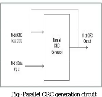
The another method of generating CRC code is parallel CRC generation. In parallel CRC generation, number of flip flops equal to the degree of generator polynomial are cascaded as shown in diagram, and input is given to each flipflop at a time. According to clock cycles it processes the data in parallel way.
Fig:-Parallel CRC generation circuit
CRCs are specifically designed to protect against common types of errors on communication channels.CRC is burst error detecting code designed to detect accidental changes to digital data in computer networks. CRC is characterized by specification called G(x), Generator Polynomial. Goal is to maximize the probability of detecting an error. In a scheme, the transmitter sends the original data, then attaches a fixed number of check bits which are derived from the data bits by some deterministic algorithm
There are different techniques for parallel CRC generation given as follow. 1. Fast CRC Update
2. Table based algorithm
3. F matrix parallel CRC generation
4. Unfolding, retiming and pipelining algorithm
Pipelined architecture
A pipeline is a technique used in the design of computers to increase their instruction throughput (the number of instructions that can be executed in a unit of time). The basic instruction cycle is broken up into a series called a pipeline. Rather than processing each instruction sequentially, each instruction is split up into a sequence of steps so different steps can be executed concurrently and in parallel by different circuitry. In this technique the next state CRC output is a function of the current state CRC and data. A linear pipeline processor is a series of processing stages which are arranged linearly to perform a specific function over a data stream.
Fig:- Pipelined architecture of parallel CRC generator circuit
The pipelined architecture in Figure has eight blocks to store input. They are used to read data from the message in each iteration. They are converted into CRC using lookup tables. LUT contains CRC values for the input. The rightmost block does not need any lookup table. It is because this architecture assumes CRC-16, the most popular CRC, and byte blocks. If the length of a binary string is smaller than the degree of the CRC generator, its CRC value is the string itself. The rightmost block it does not have any following zero and thus its CRC is the block itself. The results are combined using XOR, and then it is combined with the output of LUT n, the CRC of the value from the previous.
In order to shorten the critical path, we introduce another stage called the temporary register stage. This makes the algorithm more scalable because more blocks can be added without increasing the critical path of the pipeline. With the pre-XOR stage, the critical path is the delay of LUT and a two-input XOR gate, and the throughput increases. Since the CRC of the first block is the first block itself, it can be easily combined with the following four blocks by appending zeros using LUT. To exploit this property, the first iteration loads the first eight bits from the message. Small lookup tables to construct LUT kin the CRC for blocks is calculated in the first iteration. The CRC is calculated according to the standard of CCITT crc-16. This standard defines the CRC generator polynomial by which the generator circuit is constructed.
set to be greater than the longest delay between pipeline stages, so that when the registers are clocked, the data that is written to them is the final result of the previous stage.
Technique uses a buffer to store the input data in bytes, which allows the computation to run at one cycle per byte (instead of one cycle per bit).
At the same time generated crc automatically processed with the data and stores into buffer.
Calculates the CRC of a message in parallel to achieve better throughput.
IV. RESULT AND DISCUSSION
This project shows the comparison between the serial and parallel implementation of CRC circuits using pipelining technique. The generator polynomial used is crc-16. The design is implemented in VHDL, simulated using Modelsim and synthesized by Altera Quartus II. The correct output is obtained after 12 clock cycles, After application of the pipelining algorithm to the same design, the output is generated after 6 clock cycle for parallel, Hence it reduces the clock cycles and thus increases the speed of the circuit.
Simulation:
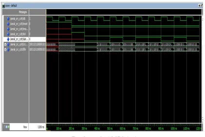
Following figures shows the simulation of circuits of serial, parallel and pipelined CRC circuits. It shows that the number of clock cycles reduces significantly in parallel design that is 8, while in serial design requires 12 clock cycles. Pipelined architecture again reduces it to 6 clock cycles which helps to increase the speed of processing
Fig :-Output of serial CRC circuit
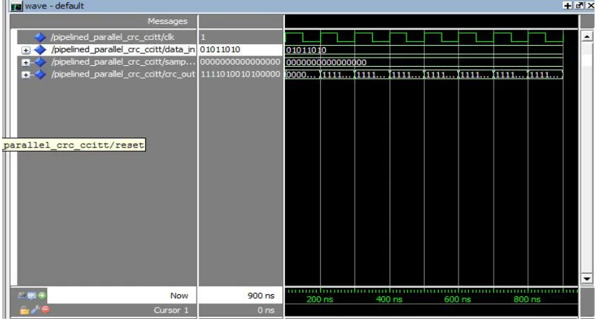
Fig :- Output of pipelined parallel CRC circuit
Above figure shows the parallel CRC simulation, it requires 8 clock cycles to produce output, less than serial clock cycles and more than the pipelined parallel cycles.
Above figure shows the pipelined parallel CRC simulation, it requires 6 clock cycles to generate the output. Hence it
requires least time to generate the output, So this method is efficient.
Implementation Comparison
Table: Comparison of implementation method
V. CONCLUSION AND FUTURE WORK
The project implements pipelining method for high-speed parallel CRC circuits. By pipelining technique we can increased the throughput of the circuit and thereby reduced the critical path delay. So applying pipelining, to the CRC, has reduced the clock cycles to achieve high speed design. The pipelined CRC method is designed to achieve high throughput by cascading buffers. The design can be implemented with DSP algorithms which improve the time further, which increase speed in practice.
ACKNOWLEDGMENTS
My special thanks to all that experts who have contributed towards development of this research paper.
REFERENCES
1. Ms.Sonali D.Solekar, Mr.P.H.Rangaree; “Design and Implementation of CRC Code Generator based on Parallel Execution Method for High Speed Wireless LAN,”IJERA.
2. Mr. Chaitali Tohgaonkar, Prof. Sanjay Tembhurne Prof. Vipin Bhure; “Design and Implementation of High Speed 64-Bit Parallel CRC
Generation,”IJAICT .
3. P.Ashok Babu, R.Vinod Kumar; “ Design and Implementation of High Speed 64-Bit Parallel CRC Generation,” IJIREC.
4. . Hitesh H. Mathukiya; Naresh M. Patel; “A Novel Approach for Parallel CRC generation for high speed application,” 2012 IEEE DOI 5. Yan Sun and Min Sik Kim; “High Performance Table-Based Algorithm for Pipelined CRC Calculation”.
6. C.Arun Kumar Chowdary, C. Kumara Narayana Swamy; “Implementation of ‘n’ bit parallel CRC using Unfolding, Retiming, Pipelining for high speed applications”
7. MING-DER SHIEH,MING-HWA SHEU, CHUNG-HO CHEN AND HSIN-FU LO; “A Systematic Approach for Parallel CRC Computations,” JOURNAL OF INFORMATION SCIENCE AND ENGINEERING.
8. Sangeeta Singh, S. Sujana, I. Babu, K. Latha, “ VLSI Implementation of Parallel CRC Using Pipelining, Unfolding and Retiming,”IOSR-JVSP,June 2013
9. B. Naveen, K. Swaraja, M. C. P Jagdissh, “Parallel CRC Generation for High Speed application,”IJITEE Oct 2013
Serial Parallel Pipelined parallel
No. of clock cycles 12 8 16
Throughput(Bytes/cycle) 63 95 127
Tp(ns) 10.118 9.742 8.76
No. of pins 21 28 28
Total logic elements 16 19 35