Strata
®
DK
Technical Bulletin
4 0 3 1 0 4 0
Strata DK424 Releases 3.2 and 4.0
I&M and Programming Updates
Version C to D
The pages included with this bulletin will update your Strata DK Installation and
Maintenance (I&M) and Programming Manuals to documentation version D. These pages provide documentation for Strata DK Software Releases 3.2 and 4.0.
This bulletin gives information on:
♦ Updating Your Office-of-Record I&M and Programming Manuals
♦ Updating Your Field I&M and Programming Manuals
♦ What’s New in Release 3.2
♦ What’s New in Release 4.0
Updating Your Office-of-Record (Paper) I&M and
Programming Manual
If you received this bulletin by mail, it has the entire Version “D” I&M and Programming manuals (insides only) attached to it. Follow these steps:
1. Remove the Version “C” insides from your I&M Manual binder. Discard these pages, or if you like, save them in your archives.
2. Insert the new Version “D” manual into the binder.
3. Remove the old black and red insert from the spine of your binder and replace it with the new one (located in the front of the Version “D” manual).
4. Repeat Steps 1~3 above with the Programming Manual.
Updating Your Field (Paper) I&M and Programming
Manual
Method #1:
➤ Refer to the I&M and/or Programming Update Pages Checklist in this section. Copy the pages listed from the updated office-of-record copy and insert them into your manual. Create your own tabs as required.
TBDK-0009 June 1, 1998
Print Version
C to D Update
Prel
imi
nary and
Con
fid
ent
ial
Method #2
Use the electronic update package on the Strata DK Library CD-ROM, Version B, June 1998:
1. Follow the instructions on the DK Library to access Adobe™ Reader® and the Home Page.
2. I&M: from the Home Page, click Installation & Maintenance, then click “Version C to Version D I&M Update Pages.”
3. Click File, then Print. If your printer is capable of duplex printing, be sure to select the two-sided setting. Or, print single-sided sheets and make two-sided photocopies.
4. Programming: from the Home Page, click Programming, then click “Version C to Version D Programming Update Pages.” Repeat Step 3.
5. Create your own tabs as required.
Important! The update files mentioned in the previous steps are intended for printing only. Therefore some buttons, hypertext links and extended search capabilities do not function.
I&M Manual Update Pages Checklist
➤ Replace the existing tabs with the enclosed tabs, which include ISDN and HMIS. Also, replace or insert the enclosed pages to update your Strata DK I&M Manual for Releases 3.2 and 4.0:
Chapter/Section Updated Pages Description
¸
Cover Page, Table of Contents, Introduction
Replace entire
sections Updated for Releases 3.2 and 4.0.
Chapter 4 Replace the entire
chapter Updated for Release 4.0. Includes E911 and ISDN information.
Chapter 5 5-47~5-62 Revised for Release 4.0.
Chapter 7
7-1/7-2 Updated for Release 4.0. Added E911 CAMA Trunk (RCMU/ RCMS) information.
7-21/7-22 Correction.
7-55~7-58 Updated for Release 4.0. Added E911 CAMA Trunk (RCMU/ RCMS) information.
Chapter 8 8-27/8-28 Updated for Release 4.0. Added E911 wiring diagram.
Chapter 13 13-5~13-16 Updated for Release 3.2. Added System Open Architecture Interface (OAI) information.
Chapter 14 Add new chapter Updated for Release 4.X. ISDN information.
Chapter 15 Add single page Reserved for future Hospitality Management Information System (HMIS) chapter.
Glossary Replace Glossary Includes ISDN, E911 terms.
Index Replace Index Updated for Releases 3.2 and 4.0. Print
Version C to D Update
TBDK-0009
Prel
imi
nary and
Con
fid
ent
ial
Programming Manual Update Pages Checklist
➤ Replace the existing tabs with the enclosed tabs, which include ISDN and E911. Also, replace or insert the enclosed pages to update your Strata DK Programming Manual for Releases 3.2 and 4.0:
Note Some of the Programming information for Release 3.2 was already updated in the Version “C” Programming Manual.
What’s New in Strata DK Release 3.2
The following contains an explanation of the new items provided in DK424 Release 3.2 software available on all RCTU, R3 processors.
Important! When upgrading RCTU3 hardware from Release 2.0, 3.0 or 3.1 software to Release 3.2, you must initialize the RCTU (Program 91-9) and restore the customer database after you change to Release 3.2 ROMs. For detailed Release 3.2 upgrade instructions, refer to bulletin TBDK-0012.
Chapter/Section Updated Pages Description
¸
Cover Page, Table of Contents, Introduction
Replace entire
section Updated for Releases 3.2 and 4.0.
Chapter 1 1-1~1-10 Updated for Releases 3.2 and 4.0.
Chapter 3
3-7~3-8 Program 03 – Updated for Release 4.0. Added ISDN cards. 3-19~3-20 Program 5 – Updated for Release 3.2.
3-25~3-36 Programs 10-1, 10-2, 10-3 – Updated for Releases 3.2 and 4.0. 3-39~3-40 Program 12 – Correction.
3-45~3-46 Program 15 – Updated for Release 3.2.
3-73~3-76 Program 30 – Updated for Releases 3.2 and 4.0. 3-97~3-102 Program 35 – Correction.
3-111~3-128 Program *38 (new), Program 39 updated for Releases 3.2 and 4.0. 3-139~3-142 Program 59 – Updated for Release 4.0.
3-161~3-162 Program 76-2 – Correction.
3-177~3-178 Program *80 – Updated for Release 3.2.
Chapter 4 4-29~4-40 Toll Restriction – Added Program *45-4.
Chapter 5 5-3~5-24 Revised for HMIS.
Chapter 6 6-7~6-8 Updated for Release 4.0. Added ISDN information.
Chapter 7 Add new chapter Updated for Release 4.0. Added ISDN information.
Chapter 8 Add new chapter Updated for Release 4.0. Added E911 CAMA information.
Glossary Replace Glossary Updated for Release 4.X. Added ISDN, E911 terms.
Index Replace Index Updated for Releases 3.2 and 4.0 Print
Version C to D Update
Prel
imi
nary and
Con
fid
ent
ial
Station Control of Ground/Loop Start CO Line Call Forward
This feature enables the installer to assign the station which controls Call Forward for each ground and loop start line. The station that controls CO line Call Forward must be the only station assigned to ring in the ringing assignment for the forwarded line. This feature also enables a group of stations to ring and answer CO line calls. If the calls are not answered, they can be sent to voice mail.
♦ Program *80–Call Forward Station Ring Assignment (new program) defines the CO line Call Forward ringing assignment (Immediate, Delay1, or Delay2) for the Day, Day2, and Night Ring modes. This record sheet provides an example of how to control Call Forward for ground/loop start CO line calls.
Once assigned, the CO line follows the Call Forward setting (Busy, No answer, etc.) of the designated control station. This feature does not apply to Tie, DID ANI, or DNIS lines which ring to a particular Directory Number (DN) and follow the Call Forward setting of the DN.
Standard Telephone Tandem Connection/Drop Out
This feature enables standard telephones and Voice Mail/Auto Attendant ports to set up a conference with two CO lines (tandem) and then drop out of the conference leaving the two CO lines connected.
The station that sets up the two CO line connection can reconnect to the tandem connection by dialing a pickup code (). If more than one tandem connection is set up by a station, the pickup code reconnects that station to the tandem connection that has the lowest CO line number as a priority.
Prior to Release 3.2 software, standard telephones could set up two CO line conferences, but they could not drop out of the connection. The Pickup Code function applies only to the station that sets up the tandem connection; a station cannot pickup a tandem connection which was set up by another station.
No new special programming is required to enable this feature; however, stations, VM ports and CO lines that must be allowed in tandem connections must be enabled in:
♦ Program 15–Ground/Loop/tie/DID Line Options, Code 5
♦ Program 31–Station Class of Service, LED 09 must be OFF for VM ports
♦ Program 10-1–System Assignments, LED 19 and 20 must be on station and VM ports
Fixed-Call-Forward Destination Enhancement
Distributed Hunt and Phantom Directory Numbers (PhDNs) can be assigned as a station’s Fixed-Call-Forward destination. Prior to R3.2 software, only Primary Directory Numbers (PDNs) could be assigned as a station’s Fixed-Call-Forward destination.
♦ Program 36–Fixed-Call-Forward assigns Distributed Hunt DN and PhDN Fixed Call Forward destinations
Ring Transfer Privacy Mode Enhancement
If Transfer Privacy is enabled in Program 10-1 (LED 08 OFF), a call that is ringing (or blind transferred) to a multiple appearing DN or CO button only rings on the DN of the primary or owner station. For example, for PDNs, this is the primary station and for PhDNs, it’s the station designated as the PhDN owner in Program *33.
Print Version
C to D Update
TBDK-0009
Prel
imi
nary and
Con
fid
ent
ial
The transferred call rings on all stations having the transferred-to DN per Programs *71, *72, and *73 before the transferring station releases (hangs-up) the call; but, rings only on the primary/owner station after the call is released.
Prior to Release 3.2 software, a transferred call rang all stations having the transferred-to DN per Programs *71, *72, *73, even after the transferring station released the call.
♦ Program 10-1–System Assignments, LED 08 OFF invokes Transfer Privacy
Voice Mail Control During Analog CO Line Conference Calls
This feature enables Toshiba digital and electronic telephones to transmit Dual-Tone Multi-frequency (DTMF) tones during CO line conference calls. The basic application of this feature enables a user to call voice mail during a conference call and play messages to all parties in the conference. This feature operates with analog ground, loop, DID and Tie lines, but not with any type of T1 (RDTU) lines.
DTMF tones can be sent from any station in the conference. When DTMF tones are sent, all parties in the conference (CO lines and telephones) receive the tones. An analog CO line must be in the conference in order for DTMF tones to be sent during a conference call. Prior to Release 3.2, DTMF tones could not be sent during any type of conference call.
No programming is required for this feature.
Camp-on Tone During I-Hold and Exclusive Hold
This enhancement sends a camp-on tone to a telephone when the telephone receives any type of call while having the DN that receives the call on I-hold or exclusive hold. The camp-on tone is two muted ring tones three seconds apart.
Prior to Release 3.2, if a DN received a call while it was on hold there was no audible or visual indication that another call was camped on to the DN. This assumed that there were no idle appearances of the DN, which would ring if called, while another appearance of the DN was on hold or exclusive hold.
No programming is required for this feature.
Disable Hold Display Scroll Option
This feature enables an installer to disable or enable the Hold Display Scroll feature
independently for each telephone. When more than one call is on hold, the Hold Display Scroll feature enables a user to scroll through the held lines. When scrolling held lines, the selected held line flashes at a faster rate than the other held lines and its number displays on the telephone’s LCD.
This flashing rate difference between held lines is confusing to some users. By using this option to turn off the Hold Display Scroll feature, held lines all flash at the same rate unless the held line recalls the telephone.
Prior to Release 3.2 software, Hold Display Scroll was enabled on all telephones and could not be disabled.
♦ Program 35–Station Class of Service, LED 6 enables/disables Hold Display Scroll.
Selective Pickup of All Call Page
This option enables pickup code to pick up All Call Page (and External Page
depending on LED 15 in Program 10-2), exclusive of ringing line pickup. If this option is ON, the pickup code picks up All Call Page and External Page only; it does not pick up ringing station-to-station or door phone calls.
Print Version
C to D Update
Prel
imi
nary and
Con
fid
ent
ial
Prior to Release 3.2, the pickup code would pick up a ringing station-to-station or door phone call as a priority over All Call Page, if the internal call was ringing at the same time as the AC or External Page needed to be picked up.
♦ Program 30–Station Class of Service, LED 04 assigns selective pickup of All Call Page.
♦ Program 10-2–System Assignments, LED 15 specifies External Page pickup.
System Open Architecture Interface (OAI) Port
With Release 3.2, an optional system-wide RS-232 application processor interface port can send caller information, plus ANI, DNIS, and Caller ID data for ACD calls, only to a centralized LAN application computer.
This application requires special software in the application computer. This port is provided for third-party developers to connect their applications when developed.
♦ Program 76-1–WSIU, TSIU and RSIU/RSIS/RMDS Port Assignments specifies the OAI port
♦ Program 76-2–WSIU, TSIU and RSIU/RSIS/RMDS Baud Rate Assignments
♦ Program 77-4–RSIU Open Architecture Interface (OAI) Data Output Assignments, LED 01 and 02 enables/disables DNIS and Caller ID/ANI independently
LCR + Toll Restriction After Dialing Special Codes
Prior to Release 3.2, calls with special dialing codes always went out as a local call using LCR. This feature enables users to dial special CO feature access codes that begin with or , plus a telephone number. Then the call is either routed via LCR or toll restricted, depending on the assigned treatment for the dialed digits. This feature is added to Program *45-3.
Example: A user can dial access code *67, to block Caller ID, plus the telephone number. The call then routes via LCR or toll restricted according to the telephone number.
Music-on-hold or Ring Back Tone for Transferred Calls
Prior to Release 3.2, transferred parties would hear Music-on-hold (MOH) or silence. With Release 3.2 and higher, transferred parties can hear MOH or Ring Back Tone (RBT). Either option is set in Program 10-2, LED 05. When LED 05 is ON, MOH plays for transferred parties; if LED 05 is OFF, RBT is sent.
What’s New in Strata DK Release 4.0
Strata DK424 Release 4.0 includes Integrated Services Digital Network (ISDN) compatibility; enhanced 911 CAMA trunk interface; Hotline Service (Emergency Ringdown); hookswitch flash operation on T1 two-way DID, ground start, and Tie lines. Another feature of Release 4.0 is that DID and Tie lines no longer require station ports in software, thus enabling higher potential capacities when using digital or analog DID or Tie lines.
Refer to the ISDN sales bulletin SBDK-0018, literature number 4027074, for more
information on Release 4.0 features. Refer to bulletin TBDK-0012 for detailed instructions on upgrading to Release 4.0. Release 4 ISDN capabilities will be released in three phases:
♦ Release 4.0 supports ISDN PRI and the other general new features.
♦ Release 4.1 will support ISDN S/T BRI capabilities. This is scheduled to become available a few weeks after Release 4.0.
♦ Release 4.2 will support ISDN U BRI and some additional PRI services. This is scheduled to become available a few months after Release 4.1.
Print Version
C to D Update
Digital Business Telephone Solutions
Installation and Maintenance
Manual
Software Releases 3.2, 4.0
and ACD
Software Release 3.1
Software Release 3.1
PrintVersion C to D Update
Publication Information
Toshiba America Information Systems, Inc., Telecommunication Systems Division, reserves the right, without prior notice, to revise this information publication for any reason, including, but not limited to, utilization of new advances in the state of technical arts or to simply change the design of this document.
Further, Toshiba America Information Systems, Inc.,
Telecommunication Systems Division, also reserves the right, without prior notice, to make such changes in equipment design or
components as engineering or manufacturing methods may warrant. Version A, December 1996
© Copyright 1996~1998
Toshiba America Information Systems, Inc. Telecommunication Systems Division
All rights reserved. No part of this manual, covered by the copyrights hereon, may be reproduced in any form or by any means—graphic, electronic, or mechanical, including recording, taping, photocopying, or information retrieval systems—without express written permission of the publisher of this material.
Stratagy and Strata are registered trademarks and Call Center Viewer is a trademark of Toshiba America Information Systems, Inc. Trademarks, registered trademarks, and service marks are the property The Strata DK Digital Business Telephone System is registered in
accordance with the provisions of Part 68 of the Federal Communications Commission’s Rules and Regulations.
FCC Requirements
Means of Connection: The Federal Communications Commission (FCC) has established rules which permit the Strata DK system to be connected directly to the telephone network. Connection points are provided by the telephone company—connections for this type of customer-provided equipment will not be provided on coin lines. Connections to party lines are subject to state tariffs.
Incidence of Harm: If the system is malfunctioning, it may also be disrupting the telephone network. The system should be disconnected until the problem can be determined and repaired. If this is not done, the telephone company may temporarily disconnect service. If possible, they will notify you in advance, but, if advance notice is not practical, you will be notified as soon as possible. You will be informed of your right to file a complaint with the FCC.
Service or Repair: For service or repair, contact your local Toshiba telecommunications distributor. To obtain the nearest Toshiba telecommunications distributor in your area, call Toshiba America Information Systems, Inc., Telecommunication Systems Division in Irvine, CA (714) 583-3700.
Telephone Network Compatibility: The telephone company may make changes in its facilities, equipment, operations, and procedures. If such changes affect the compatibility or use of the Strata DK system, the telephone company will notify you in advance to give you an opportunity to maintain uninterrupted service.
Notification of Telephone Company: Before connecting a Strata DK system to the telephone network, the telephone company may request the following:
1. Your telephone number. 2. FCC registration number:
♦ Strata DK may be configured as a Key or Hybrid telephone system. The appropriate configuration for your system is dependent upon your operation of the system.
♦ If the operation of your system is only manual selection of outgoing lines, it may be registered as a Key telephone system.
♦ If your operation requires automatic selection of outgoing lines, such as dial access, Least Cost Routing, Pooled Line Buttons, etc., the system must be registered as a Hybrid telephone system. In addition to the above, certain features (tie Lines, Off-premises Stations, etc.) may also require Hybrid telephone system registration in some areas.
DK14 and DK40
Key system: CJ6MLA-74479-KF-E
Hybrid: CJ6MLA-74478-MF-E DK424
Hybrid: CJ69XA-10243-MF-E
Key system: CJ69XA-10242-KF-E
PBX: CJCHN-22757-PF-E
3. Ringer equivalence number: 0.3B. The ringer equivalence number (REN) is useful to determine the quantity of devices which you may connect to your telephone line and still have all of those devices ring when your number is called. In most areas, but not all, the sum of the RENs of all devices connected to one line should not exceed five (5.0B). To be certain of the number of devices you may connect to your line, as determined by the REN, you should contact your local telephone company to ascertain the maximum REN for your calling area.
4. Network connection information USOC jack required: RJ1CX, RJ2EX, RJ2GX, RJ48C, RJ48X, RJ11, RJ14C, RJ21X (see Network Requirements in this document). Items 2, 3 and 4 are also indicated on the equipment label.
Radio Frequency Interference
Warning: This equipment generates, uses, and can radiate radio frequency energy and if not installed and used in accordance with the manufacturer’s instruction manual, may cause interference to radio communications. It has been tested and found to comply with the limits for a Class A computing device pursuant to Subpart J of Part 15 of FCC Rules, which are designed to provide reasonable protection against such interference when operated in a commercial environment. Operation of this equipment in a residential area is likely to cause interference, in which case, the user, at his/her own expense, will be required to take whatever measures may be required to correct the interference.
This system is listed with Underwriters Laboratory. UL Requirement: If wiring from any telephone exits the building or is subject to lightning or other electrical surges, then secondary protection is required. Secondary protection is also required on DID, OPS, and tie lines. (Additional information is provided in this manual.)
Important Notice — Music-On-Hold
In accordance with U.S. Copyright Law, a license may be required from the American Society of Composers, Authors and Publishers, or other similar organization, if radio or TV broadcasts are transmitted through the music-on-hold feature of this telecommunication system. Toshiba America
U L
®Print Version
C to D Update
Contents
Introduction
Organization ... vii Conventions... ix Related Documentation ... x
Chapter 1 – DK14 Installation
Inspection ... 1-1 Packaging and Storage ... 1-1 Site Requirements ... 1-1 AC Power and Grounding Requirements... 1-3 KSU Mounting Considerations ... 1-5 Reserve Power Battery ... 1-8 Power Supply Removal and Replacement ... 1-9 Printed Circuit Board (PCB) Installation ... 1-11 Built-in CO Line, Digital, Telephone, and Other Circuits ... 1-13 QCDU2 CO Line Digital Telephone Interface Unit ... 1-14 QSTU2A Standard Telephone Interface Unit ... 1-16 QRCU3 DTMF Receiver/ABR Tone Detector Unit ... 1-18 WSIU1 Serial Interface Board ... 1-19 DK8/DK14 Compatibility ... 1-21 DK14 Secondary Protection... 1-22 DK14 Wiring Diagrams ... 1-23
Chapter 2 – DK40 Configuration
Base Key Service Unit (KSU)... ... 2-1 Expansion KSU ... 2-3 Feature Capacities ... 2-7 Station Considerations ... 2-9 Telephone Circuit (Port) Types... 2-10 Worksheet 1 – System PCB Assignment Guide ... 2-12 Worksheet 2 – System Power Factor (PF) Check ... 2-48 Strata DK16/DK16e/DK40 Component Compatibility ... 2-51 Print
Version C to D Update
Packaging and Storage ... 3-1 Site Requirements ... 3-1 AC Power and Grounding Requirements... 3-4 KSU Mounting Considerations ... 3-5 Reserve Power Option... 3-17 Power Failure Emergency Transfer Option ... 3-19 Power Supply Removal and Replacement ... 3-20 Printed Circuit Board (PCB) Installation ... 3-21 K4RCU3 and K5RCU DTMF Receiver/ABR Tone Detector Unit ...3-23 KKYS Auto Attendant ...3-24 KSTU2 Four-circuit Standard Telephone Interface Unit...3-25 TCIU Caller ID ...3-28 TCOU Four-circuit Loop Start CO Line Board ...3-30 TDDU Four-circuit DID Line Digital Telephone Interface Unit...3-33 TSIU Serial Interface Board...3-36 Universal Slot PCBs... 3-38 Loop Limits ... 3-39 DK40 Secondary Protection... 3-40 MDF Wiring Diagrams ... 3-41
Chapter 4 – DK424 Configuration
System Configuration... 4-1 System Capacity... 4-8 Printed Circuit Boards... 4-12 Telephones ... 4-16 Attendant Position Options ... 4-16 Direct Station Selection (DSS) Consoles and Door Phones (MDFBs)... 4-16 AC and Reserve Power Hardware... 4-18 Floor Mount Installation Hardware... 4-18 Worksheets ... 4-19 Worksheet 1 – System PCB (Slot) Requirements... 4-20 Worksheet 2 – System Cabinet Assignment Guide ... 4-28 Worksheet 3 – System PCB Assignment Guide ... 4-29 Worksheet 4 – Option Configuration Guide ... 4-31 Worksheet 5 – System Power Factor Check ... 4-34
Chapter 5 – DK424 Installation
Inspection ... 5-1 Packaging and Storage ... 5-1 Site Requirements ... 5-2 Cabinet Installation Considerations ... 5-8 Power Supply Installation ... 5-9 Wall Mounting the Base Cabinet ... 5-12 Cabinet Floor Mounting ... 5-22 AC Power and Grounding Requirements... 5-29 AC Power Cabling Installation ... 5-31 Print
Version C to D Update
Reserve Power Installation... 5-33 Printed Circuit Board (PCB) Installation ... 5-47 RCTUA, RCTUBA/BB, RCTUC/D, RCTUE/F
Common Control Units ... 5-48
Chapter 6 – DK424 T1
Channelization... 6-1 Slot Assignments... 6-1 Installation Guidelines ... 6-10 Applications ... 6-11 Hardware and Cabling... 6-13 Loop Back Testing ... 6-16 Performance Monitoring ... 6-18 T1 Fault Isolation ... 6-20
Chapter 7 – DK40/DK424 Universal Slot PCBs
PCB Chapter Layout ... 7-3 KCDU CO Line/Digital Telephone Interface Unit ...7-4 PDKU2 Digital Telephone Interface Unit... 7-6 PEKU Electronic Telephone Interface Unit...7-8 PEPU External Page Interface Unit ... 7-11 PESU Standard/Electronic Telephone Interface Unit ...7-13 PIOU, PIOUS Option Interface Units ...7-17 RATU Attendant Console Interface Unit...7-21 RCIU1, RCIU2, RCIS Caller ID Interface...7-22 RCOU, RCOS Four-Circuit Loop Start CO Line Interface Unit ...7-27 RDDU Direct Inward Dialing Line Interface Unit ...7-32 RDSU Digital/Standard Telephone Interface Unit ...7-35 RDTU T1 Interface Unit ... 7-37 REMU Tie Line Unit ...7-38 RGLU2 Loop/Ground Start CO Line Interface Unit ...7-42 RSIU, RSIS, RMDS RS-232/Modem Interface Unit... 7-44 RSSU PC Interface Unit...7-50 RSTU2 Standard Telephone Interface Unit ...7-51 RMCU/RCMS E911 CAMA Trunk Direct Interface ...7-54
Chapter 8 – DK40/DK424 Universal Slot PCB Wiring
Station Wiring Diagrams... 8-2 Digital Station Wiring ... 8-2 Power Failure Cut Through (DPFT) Wiring Pin-outs... 8-21 CO Line Wiring Diagrams ... 8-23 Option Interface PCB Wiring Diagrams ... 8-33
Chapter 9 – Station Apparatus
Types of Telephones ... ... 9-1 Telephone Installation ... ... 9-3 Telephone Upgrades... ... 9-6 Print
Version C to D Update
Door Phone (MDFB)... 9-22 Lock Control Unit and Door Phone ... 9-22 Cordless Digital Telephone (DKT2004-CT) ... 9-24 Digital Add-on Module Installation ... 9-31 PC Attendant Console ... 9-33 Conventional Attendant Console ... 9-52
Chapter 10 – Peripheral Installation
Power Failure Options... 10-1 Music-on-Hold (MOH)/ Background Music (BGM) Options ... 10-3 Relay Control Options and Door Lock Control ... 10-10 External Speaker Unit (HESB) Options... 10-19 External Page Options... 10-26 Two-CO Line External Amplified Conference... 10-32 SMDR Printer/Call Accounting Device Options ... 10-35 System Database Printout Using SMDR Port... 10-41 Voice Mail Options ... 10-42 PC/Data Communications Interface Units ... 10-47 DK Alarm Sensor ... 10-75 Auto Attendant ... 10-76 Multiple PIOU, PIOUS, RSSU Installation ... 10-83 Enhanced 911 Service (E911) ... 10-85
Chapter 11 – DK424 ACD Installation
Installation... 11-2 ACD Installation Guidelines ... 11-4 ACD Line Operation/Programming Considerations ... 11-6 Call Center Viewer (CCV)... 11-15 CCV Configuration ... 11-17 CCV Configuration Instructions ... 11-20 Spectrum Electronic Wall Boards ... 11-24
Chapter 12 – Fault Finding
Fault Classification... 12-1 Fault Clearing Procedures ... 12-1 Defective Parts Return ... 12-3 KSU/RCTU Fault Isolation... 12-3 DK424 RPSU280 Power Supply Test... 12-4 Station Cable Continuity Check... 12-7 Fault Isolation Flowcharts... 12-10
Chapter 13 – Computer Telephony Integration
About Strata DK and TAPI ... ... 13-1 Requirements... 13-1 StrataLink and TAPI Service Provider for Windows 95 ... 13-2 Print
Version C to D Update
System Open Architecture ... 13-6 CTI Application Bulletin Contents ... 13-15
Chapter 14 – DK424 ISDN Interfaces
Timing and Synchronization ... 14-11 RPTU Call Monitoring (PRI)... 14-13 SMDR Output for ISDN ... 14-18
Chapter 15 – Hospitality Management Information System (HMIS)
Glossary
... ... GL-1Index
...IN-1Print Version
C to D Update
Introduction
This manual provides detailed step-by-step instructions for installing and maintaining the Strata DK14 / DK40 / DK424 digital business telephone systems. It is intended for qualified service technicians and system programmers. At the time of this printing, this book contains Release 4.0 information for the DK424. It also contains some pre-release information for software beyond Release 4.0.
Important! Information beyond Release 4.0 is preliminary and given prior to product release. Be careful when using this information as the software will change and updates/additions will be required upon final release.
Use this manual in conjunction with the Strata DK Programming Manual which covers the programs related to the Strata DK systems discussed in this book.
Organization
In this manual, information specific to one system is clearly marked for that system whether in a chapter title or within a chapter (e.g., DK40 CO Line/Digital Telephone Interface Unit (KCDU) found in Chapter 7). Unmarked information should be considered to be general to all Strata DK systems discussed in this book.
This manual is organized into these sections/chapters for your convenience:
♦ General Description provides an overview of the Strata DK systems and associated
hardware.
♦ Chapter 1 – DK14 Installation covers site requirements and explains how to install
Strata DK14 Key Service Unit (KSU). Includes power requirements, cable lengths/ network and grounding requirements.
♦ Chapter 2 – DK40 Configuration explains how to configure a Strata DK40 system. It
also provides space to record the hardware and station devices that make up the system.
♦ Chapter 3 – DK40 Installation covers site requirements and cabinet installation
information. Defines the installation site requirements necessary to ensure a proper operating environment for the Strata DK40. Also included are input power requirements, cable lengths/network requirements, and grounding requirements. Explains how to install both the Base Key Service Unit (KSU) and the Expansion KSU. Instructions are also provided on how to remove and replace cabinets on installed systems.
♦ Chapter 4 – DK424 Configuration explains how to configure a Strata DK424 system. It
also provides worksheets for determining hardware and station equipment placement and requirements.
♦ Chapter 5 – DK424 Installation covers site requirements and cabinet installation
information. Defines the installation site requirements necessary to ensure a proper operating environment for the Strata DK424. Also included are input power requirements, Print
Version C to D Update
cable lengths/network requirements, and grounding requirements. Explains how to install both the Base and the Expansion Cabinets. Instructions are also provided on how to remove and replace cabinets on installed systems.
♦ Chapter 6 – DK424 T1 provides information on T1/DS-1 interfacing for the DK424. T1/
DS-1 interfacing is not available for the DK14 and DK40.
♦ Chapter 7 – DK Universal Slot PCBs provides procedures for Strata DK40/DK424
system Printed Circuit Boards (PCBs) for installation into universal slots. It includes installation instructions, optional configuration information, and wiring and programming considerations for each PCB.
Note PCBs that cannot be installed into universal slots can be found in the installation chapter for the system (e.g., Chapter 3 – DK40 Installation).
♦ Chapter 8 – DK Universal Slot PCB Wiring contains point-to-point wiring diagrams for
connection of telephones, lines, peripheral equipment, and power supplies to the Strata DK systems.
Note Wiring diagrams for PCBs that cannot be installed into universal slots can be found in the installation chapter for the system (e.g., Chapter 3 – DK40 Installation).
♦ Chapter 9 – Station Apparatus provides instructions on how to connect telephones to the
Strata DK systems and how to configure and upgrade them for optional features.
Procedures for installing direct station selection consoles, PC and conventional attendant consoles, and door phones also appear.
♦ Chapter 10 – Peripheral Installation provides connection procedures for optional
peripheral equipment to Strata DK systems. The instructions for each option include hardware requirements, PCB configuration, interconnection/wiring requirements, and programming considerations.
♦ Chapter 11 – DK424 ACD Installation includes installation instructions for Automatic
Call Distribution (ACD) and Management Information System (MIS) for the Strata DK424 (applies to all common control processors except the RCTUA). Includes
installation instructions for Call Center Viewer. ACD and MIS is not available to the DK14 and DK40.
♦ Chapter 12 – Fault Finding for troubleshooting and fixing problems.
♦ Chapter 13 – Computer Telephony Integration (CTI) contains CTI, TAPI, and System
Open Architecture Interface information. CTI application notes can be inserted here.
♦ Chapter 14 – ISDN contains an overview of the ISDN hardware with specific information
on the ISDN Primary Rate Interface (PRI) and Basic Rate Interfaces (BRI). It includes instructions for installation, hardware requirements, wiring requirements, and some programming considerations.
♦ Chapter 15 – Hospitality Management Information System (HMIS) (This chapter
will be issued upon release of the product.)
♦ Appendix A – Technical Bulletins provides a place for your updates and bulletins.
♦ Glossary/Index Print
Version C to D Update
Introduction Conventions
Conventions
This manual uses these conventions:
Note Elaborates specific items or reference other information. Within some tables, General Notes apply to the entire table and numbered Notes apply to specific items.
Important! Calls attention to important instructions or information.
CAUTION! Advises you that hardware, software applications or data could be damaged
if the instructions are not followed closely.
Why Are Some Cross References and Text Grey in the Paper Version?
Grey cross references and text in the paper version of this manual indicate the blue hypertext links in the electronic version (DK Library CD-ROM or FYI Internet download). They are included in the paper version to help speed up locating these links when using in conjunction with the electronic version.
WARNING! Alerts you when the given task could cause personal injury or death.
represents telephone buttons.
[DN] any Directory Number button (also known as an Extension or Intercom Number).
[PDN] Primary Directory Number button (the Extension Number for the telephone).
[SDN] Secondary appearance of a [PDN]. A [PDN] which appears on another telephone is considered an [SDN].
[PhDN] Phantom Directory Number button (an additional Directory Number).
Courier shows a computer keyboard entry or screen display. “Type” indicates entry of a string of text. “Press” indicates entry of a single key.
Example of both: Type prog then press Enter.
+ shows a multiple PC keyboard or phone button entry. Entries without spaces between them show a simultaneous entry.
Example: Delete+Enter.
Entries with spaces between them show a sequential entry.
Example: + .
~ means “through”.
➤
denotes the beginning of step-by-step instructions.➤ denotes the step in a one-step procedure. Print
Version C to D Update
Related Documentation
The following is a list of Strata DK reference documents:
♦ Strata DK Programming Manual provides all instructions necessary to program the
system and system record sheets, including ACD. It also contains the user guides in a reduced-size format.
♦ Digital Telephone User Guide provides necessary procedures to operate
Toshiba-proprietary digital and digital Liquid Crystal Display (LCD) telephones. It also includes operating instructions for add-on modules and DSS consoles.
♦ Digital Telephone Quick Reference Guide provides a quick reference for
frequently-used digital telephone features.
♦ Electronic Telephone User Guide provides necessary procedures to operate
Toshiba-proprietary electronic and electronic Liquid Crystal Display (LCD) telephones. It also includes operating instructions for add-on modules and HDSS consoles.
♦ Electronic Telephone Quick Reference Guide provides a quick reference for
frequently-used electronic telephone features.
♦ Standard Telephone User Guide gives procedures to operate rotary dial and push-button
standard telephones.
♦ Cordless Telephone User Guide shows how to use the DKT2004-CT cordless digital
telephone as a single unit or in conjunction with a digital telephone.
♦ PC Attendant Console User Guide provides necessary procedures to operate the
Toshiba-proprietary PC Attendant Console.
♦ PC Attendant Console Quick Reference Guide provides a quick reference for
frequently-used PC Attendant Console features.
♦ PC/Data Interface User Guide explains all the procedures necessary to operate
stand-alone data interface units while in the data mode of the Integrated Personal Computer Interface. Also provides instructions on connecting to Telephone Application
Programming Interface (TAPI).
♦ PC Digital Telephone User Guide provides installation and operation information for
Toshiba’s Personal Computer Digital Key Telephone (PC-DKT) system working with Strata DK systems. The PC Digital Telephone works with Microsoft® Windows® software. ♦ System Administrator's Guide gives instructions for the System Administrator to
manage the system. Contains instructions for Station Relocation, System Speed Dial, and other features only activated by the System Administrator.
♦ Feature Description Manual describes each feature associated with the Strata DK
systems. Also describes compatible Toshiba-proprietary telephones and peripherals.
♦ DKQuote Guide shows how to use this interactive software with an IBM-compatible PC,
to assist you with configuration and pricing worksheets.
♦ DKBackup/Admin Guide explains how to use the DKBackup storage and retrieval
administration software, which enables you to backup and restore Strata DK customer programmed data and save the data on an IBM-compatible PC. This guide also describes how to use DKAdmin, an interactive software application that lets you easily and quickly custom program and update all Strata DK systems with a user-friendly PC display. Print
Version C to D Update
Introduction Related Documentation
♦ Keyprint 2000 Guide provides instructions for the Keyprint 2000 software printing
package which allows you to print and store custom button label keystrips for Strata DK 2000-series 10-button or 20-button digital telephones, 20-button add-on modules, and 60-button digital DSS consoles.
♦ Strata DK Library CD-ROM enables you to view, print, navigate and search
publications for Strata DK14, DK40 and DK424 Digital Business Telephone Systems.
♦ Hospitality Management Information System (HMIS) General Description provides
an overall view of the system’s hardware, software, applications and features. The HMIS is a PC-based solution, designed to meet the specific operational needs of small- to medium-sized hotel/motels and includes both the PC and software.
♦ Hospitality Management Information System (HMIS) User Guide describes the
product’s many software features and gives step-by-step instructions for using them.
Print Version
C to D Update
Print Version
C to D Update
DK424 Configuration
4
This chapter explains how to configure the Strata DK424 system. The system has a modular design which enables it to support a number of station and CO line configurations. The main component of the system is the common control unit (RCTU) Printed Circuit Board (PCB).
The focus of this chapter is a series of worksheets, providing a systematic procedure for determining the system’s size. The worksheets also provide space to record the hardware and station devices that make up the system. Tables and example worksheets are included to assist you in filling out the worksheets.
Important! Prior to Release 4, tie and DID lines used station ports. With Release 4
processors, these lines do not use station ports, allowing larger capacity systems when tie and DID lines are required.
System Configuration
Important!
System Configuration can be complex and time consuming. For best results:
● Use DKQuote to provide easy, fast, automated configuration. It runs on an
IBM-compatible Pentium® PC or higher, equipped with a 110MB or larger hard drive, a 3.5” 1.44 MB high density floppy disk drive, 16MB RAM, and Windows® 95 or Windows NT®. See the DKQuote User Guide for more information.
● If the above software is not available, use the Worksheets in this chapter.
The DK424’s main components are: the DK424 Base Cabinet (DKSUB424), DK424 Expansion Cabinets (DKSUE424), and four system processors (RCTUA4, RCTUBA3/BB4, RCTUC3/D4, and RCTUE3/F4). The processor used in the system depends on the features and number of telephones and CO lines required. Each cabinet is shipped with its required Power Supply (RPSU280); the same power supply used in DK280 cabinets.
See Chapter 5 – DK424 Installation for detailed information on installing RCTU PCBs.
Base Cabinet
The DK424 Base Cabinet provides two designated slots for the RCTU processor and six universal slots for station, line, and feature PCBs. It provides six connectors for expanding the system to a maximum of six Expansion Cabinets. It comes with a Motherboard Jumper Unit (MBJU) installed between the R11 and RCTU slot on the front side of the backplane
motherboard. The MBJU is removed only when RCTUE/F is installed. MBJU is installed for all other DK Release 1~4 RCTU processor PCBs.
Print Version
C to D Update
Expansion Cabinets
Cabinet and Universal Slot Capacity: Up to six DK424 Expansion Cabinets can be connected to a DK424 Base Cabinet. The number of DK424 Expansion Cabinets allowed depends on which processor is installed in the DK424 Base Cabinet.
The DK424 Expansion Cabinets support either six or eight universal slots, depending on which processor is installed in the DK424 Base Cabinet.
♦ All Expansion Cabinets are six slot cabinets except DK424 Expansion Cabinets. DK424 Expansion Cabinets provide eight slots, but only when connected to a DK424 Base Cabinet controlled by an RCTUE3/F3 processor with the MBJU removed (see Table 4-1
below).
♦ No DK424 Expansion Cabinets are allowed when connected to the DK424 Base Cabinet with an RCTUA processor installed.
♦ One DK424 Expansion Cabinet provides six universal slots when connected to the DK424 Base Cabinet with an RCTUBA/BB processor installed.
♦ Up to five DK424 Expansion Cabinets provide six universal slots each, when connected to the DK424 Base Cabinet with an RCTUC/D processor installed.
♦ Up to six DK424 Expansion Cabinets provide eight universal slots each, when connected to a DK424 Base Cabinet with an RCTUE/F processor installed.
Table 4-1 shows DK424 cabinet and slot capacities for Release 3 and 4 processors.
1 All Cabinets are DK424.
2 Only the RCTUE/F processor allows up to eight universal slots in the DK424 Expansion Cabinet.
DK424 and DK280 Compatibility
DK424 cabinets replace DK280 cabinets in the DK product line structure. DK424 Expansion Cabinets began shipping in June 1995 and DK424 Base Cabinets in February 1997. All old DK280 Release 1~3 processors and DK280 Base/Expansion Cabinets can be mixed with new DK424 Base and Expansion Cabinets with the following criteria (see Tables 4-2,4-3):
Table 4-1 DK424 Cabinet and Expansion Slot Capacity
Processor in DK424 Base Cabinet1
DK424 Expansion Cabinets Allowed
Universal Slots allowed in DK424
Base Cabinet
Universal Slots allowed per DK424 Expansion Cabinet
Universal Slots per System
RCTUA 0 1~6 0 6
RCTUBA/BB 1 1~6 1~6 12
RCTUC/D 5 1~6 1~6 36
RCTUE/F 6 1~6 1~82 54
Print Version
C to D Update
DK424 Configuration System Configuration
1 Last Expansion Cabinet must be a DK424.
2 Depends on the combination of Expansion Cabinets.
♦ DK424 and DK280 Cabinets can be mixed in any combination, with one exception. If
seven cabinets are required, an RCTUE/F processor must be installed in a DK424 Base Cabinet and the sixth Expansion Cabinet must be a DK424. In this case DK280 Expansion Cabinets provide six universal slots and DK424 Expansion Cabinets provide eight
universal slots.
♦ DK280 and DK424 Base Cabinets provide six universal slots maximum in any
configuration and any RCTU processor can be installed.
♦ DK280 Expansion Cabinets provide six universal slots maximum in any configuration.
♦ DK424 Expansion Cabinets provide six universal slots maximum in any configuration with
a DK280 Base Cabinet, including a DK280 Base Cabinet with an RCTUE/F processor.
♦ DK424 Expansion Cabinets provide eight universal slots in one configuration only: when
connected to a DK424 Base Cabinet controlled by an RCTUE/F processor (MBJU jumper must be removed - see installation for details). DK424 cabinets provide six universal slots in all other configurations.
♦ An RCTUE/F processor can be installed in a DK280 Base Cabinet. When an RCTUE/F
processor is installed in a DK280 Base, only five Expansion Cabinets (DK424 and/or DK280) can be installed. These Expansion Cabinets provide only six universal slots. Table 4-2 DK280 Base with DK280 and/or DK424 Expansion Cabinets
Processor in DK280 Base Cabinet
Expansion Cabinets Allowed
Universal Slots allowed in Base
Cabinet
Universal Slots allowed per Expansion Cabinet
Universal Slots per System
RCTUA1, RCTUA3,
RCTUA4 0 1~6 0 6
RCTUB1, RCTUB2, RCTUBA3/BB3 or RCTUBA3/BB4
1 1~6 1~6 12
RCTUC/D2, RCTUC3/D3, RCTUE3/F3 RCTUE3/F4
5 1~6 1~6 36
Table 4-3 DK424 Base with DK280 and/or DK424 Expansion Cabinets
Processor in DK424 Base Cabinet
Expansion Cabinets Allowed
Universal Slots allowed in Base
Cabinet
Universal Slots allowed per Expansion Cabinet
Universal Slots per System
RCTUA1, RCTUA3,
RCTUA4 0 1~6 0 6
RCTUB1, RCTUB2, RCTUBA3/BB3 or RCTUBA3/BB4
1 1~6 1~6 12
RCTUC/D2, RCTUC3/D3, RCTUC3/D4
5 1~6 1~6 36
RCTUE3/F3
RCTUE3/F4 61 1~6
1~6 for DK280 Exp. Cabs.
1~8 for DK424 Exp. Cabs.
36~542 Print
Version C to D Update
♦ All older DK280 Release 1~3 processors will function in the DK424 Base Cabinet. The
features available depend on the respective release and type of the RCTU. These processors include RCTUA1, RCTUA3, RCTUB1, RCTUB2, RCTUBA3/BB3, RCTUC1/D2 and RCTUC3/D3.
♦ When an older processor is installed in the DK424 Base Cabinet, the DK424 and DK280 Expansion Cabinets provide six universal slots and the MBJU jumper must be installed - see RCTU installation for details.
♦ RCTUA in a DK424 Base allows no Expansion Cabinets.
♦ RCTUB or RCTUBA/BB in a DK424 Base allows one DK424 or DK280 Expansion Cabinet with six universal slots.
♦ RCTUC/D in a DK424 Base allows up to five DK424 and DK280 Expansion Cabinets in any combination. These Expansion Cabinets provide six universal slots.
Designated Speaker OCA, DIU Data, and T1 slots
DK424 systems require that PDKU2 PCBs that support Speaker Off-Hook-Call-Announce (OCA) and PDIU-DS and RPCI-DI PCBs for data applications must be placed in the slots designated in Tables 4-4 and 4-5.
Note PDKU2s that support Handset OCA and RPCI TAPI-only can operate in any slot.
Additionally, to enable T1/DS-1 interface, the RDTU PCB(s) must be placed in certain slots, with corresponding slots left vacant. (The operation of certain channels necessitates vacant slots.) RDTU PCBs can be placed in the slots in bold type; the vacant slots are not in bold in the following tables.
Example: for cabinet 1, if an RDTU is placed in slot 13 and you want to use RDTU channels 17~24, then slot 14 must be left vacant. If you installed a second RDTU, it would go into slot 15; slot 16 must also be vacant if you want to use RDTU channels 17~24.
1 Slot must be vacant for RDTU channels 17-24 (2-slot RDTU positions). 2 Slot must be vacant for RDTU channels 9-16 (3-slot RDTU positions). 3 Slot must be vacant for RDTU channels 17-24 (3-slot RDTU positions).
Table 4-4 DK424 Base Cabinet with RCTU3/F with MBJU Removed
Cabinet Total Universal Slots
PDKU2 Data and Speaker
OCA Slots RDTU/Vacant Slots No. Type
1 DK424 (base) 6 11, 12, 13, 14, 15, 16 13/141 15/161
2 DK280 6 21, 22, 23, 24, 25, 26, 21/221 23/241 25/261
2 DK424 8 21, 22, 23, 24 21/221 23/241 25/272/263
3 DK280 6 31, 32 31/321 33/352/343
3 DK424 8 31, 32, 37, 38 31/321 33/352/343 37/381
4 DK280 6 41, 42 41/421 43/452/443
4 DK424 8 41, 42, 47, 48 41/421 43/452/443 47/481
5 DK280 6 51, 52 51/521 53/552/543
5 DK424 8 51, 52, 57, 58 51/521 53/552/543 57/581
6 DK280 6 61, 62 61/621 63/652/643
6 DK424 8 61, 62, 67, 68 61/621 63/652/643 67/681
7 DK280 6 Cannot be seventh cabinet
7 DK424 8 No Data & Spkr OCA 71/772/723 73/752/743 Print
Version C to D Update
DK424 Configuration System Configuration
Table 4-5 pertains to a DK424 Base Cabinet with RCTU-A1, A3, A4, B2, BA3/BB3 or BA3/ BB4, C1/D2, C3/D3 or C3/D4 with MBJU or a DK280 Base Cabinet with RCTU-A1, A3, A4, B2, BA3/BB3, BA3/BB4, C1/D2, C3/D3, C3/D4, E3/F3, E3/F4.
1 Slot must be vacant for RDTU channels 17-24 (2-slot RDTU positions). 2 Slot must be vacant for RDTU channels 9-16 (3-slot RDTU positions). 3 Slot must be vacant for RDTU channels 17-24 (3-slot RDTU positions).
Notes
Applies to Tables 4-4 and 4-5:
● RCTUA does not support RDTU.
● RCTUB and RCTUBA/BB supports Cabinet 1 and 2 only.
DK280 to DK424 Upgrades
To upgrade an existing DK280 Base Cabinet to a DK424 Base Cabinet with an RCTUE/F processor, see “DK280 to DK424 Base Cabinet Upgrade Considerations” on Page 5-54. Table 4-5 DK424 or DK280 Base Cabinet with MBJU
Cabinet Total Universal Slots
PDKU2 Data and
Speaker OCA Slots RDTU /Vacant Slots
No. Type
1 DK424 or DK280 (base) 6 11, 12, 13, 14, 15, 16 13/141 15/161
2 DK424 or DK280 6 21, 22, 23, 24, 25, 26 21/221 23/241 25/261
3 DK280 or DK424 6 31, 32 31/321 33/352/343
4 DK280 or DK424 6 41, 42 41/421 43/452/443
5 DK280 or DK424 6 51, 52 51/521 53/552/543
6 DK280 or DK424 6 61, 62 61/621 63/652/643
Print Version
C to D Update
The features and capacities of DK424 system processors are provided in Tables 4-6~4-8.
Table 4-6 System Feature Capacities
DK424
Features DK14 DK40 RCTUA RCTUBA/
BB RCTUC/D RCTUE/F
Amplified Conferencing1
1. Requires additional customer-supplied hardware.
0 2 4 4 4 4
Auto Attendant (built-in) simultaneous
announcements 3 5 12 12 24 24
Caller ID/ANI/CNIS Abandoned Call Numbers:
stored per station 10~100 10~100 10~100 10~100 10~100 10~100
stored per system 200 200 200 400 1000 2000
CO Line Groups 4 8 8 8 16 16
Distributed Hunt (DH) Calls in Queue per Groups 10 10 10 10 10 10
DH Groups 16 16 16 16 16 16
DH stations per Group 8 28 32 32 32 32
DNIS Network Routing Numbers 0 100 100 200 300 300
DNIS Numbers 0 200 200 350 500 500
DTMF receivers 3 5 12 12 24 24
External Page Zones 0 4 4 4 4 8
Call Park Orbits - general 20 20 20 20 20 20
Call Park Orbits - individual 10 28 32 80 240 336
Personal LCD Messages per DKT2
2. Personal Messages includes: timed reminder memo and station speed dial memo.
10 10 10 10 10 10
Personal Message DKTs 8 16 16 32 96 96
[PhDNs] per System 10 28 32 80 240 336
[PDNs] per System 10 28 32 80 240 336
Ring Tones 3 3 3 3 3 3
Simultaneous Party Conferencing (4-party) 2 3 3 7 7 14
Simultaneous Two-CO Line conferencing
(3-party) 2 4 4 10 10 20
Station Speed Dial 40 40 40 40 40 40
Stratagy DK Systems (per tenant group) 1 1 1 1 1 1
Stratagy DK Systems (per system) 0 2 2 2 4 4
System LCD Messages 40 40 40 40 40 40
System Speed Dial 40 40 40 100 100 800
Telephone Page Groups 5 5 5 5 9 9
Telephone Group Page – simultaneous stations
paged 8 28 32 80 120 120
Telephone Pickup Groups 8 20 20 20 20 20
Tenants 2 2 2 4 4 4
Toll Restriction (AC/OC) Table 8 8 8 8 16 16
Toll Restriction Classes 4 4 4 4 8 8
Verified Account Codes 300 300 300 300 300 500
Voice Mail SMDI Yes Yes Yes Yes Yes Yes
Print Version
C to D Update
DK424 Configuration System Configuration
Table 4-7 Line Capacities and Universal Printed Circuit Board Slots
DK424
Lines and PCB Slots DK14 DK40 RCTUA RCTUBA/BB RCTUC/D RCTUE/F
Universal slots 0 41
1. There are four universal slots in the DK40 expansion unit.
6 12 36 54
CO lines – loop start 4 12 2 16 2
2. All CO line capacities assume a PIOU, PIOUS, PEPU, RSSU, or RSIU is installed for RCTUBA/BB, RCTUC/D or RCTUE/F, but no Caller ID RCIU2/RCIS PCBs.
48 2 144 2 200 2
CO lines – ground start 0 12 16 2 40 2 136 2 200 2
DID lines (analog) 0 12 16 3
3. Limits apply to analog DID and tie lines, not T1 DID/tie lines.
40 3 136 3 200 3
Tie lines (analog) 0 12 16 3 40 3 136 3 200 3
T1 (DS-1) lines each) 0 0 0 484
4. T1 lines can be loop start, ground start, tie, or DID (maximum 24 lines per unit, any type or combination).
144 4 192 4 ISDN BRI (S/T or U) B channel lines 0 0 85
5. BRI lines provide CO line services, including Caller ID, DID and Direct Inward Lines (DIL).
16 5 16 5 16 5
ISDN PRI (T) B channel lines 0 0 0 47 6
6. PRI lines provide CO line services, including Caller ID, ANI, DID, tie, POTS, FX and DIL.
141 6 188 6 Squared System Maximum
(lines + stations)
4 lines + 4 stations
12 lines + 12 stations
16 lines + 16 stations
48 lines + 48 stations
144 lines + 144 stations
200 lines + 200 stations
Table 4-8 Station and Peripherals Capacities
DK424
Stations DK14 DK40 RCTUA RCTUBA/BB RCTUC/D RCTUE/F
Add-on modules (DADM) 8 12 12 40 120 200
Attendant consoles 0 0 0 2 4 4
DKT 2004-CT Cordless Telephones 8 28 32 80 240 336
DKT 2004-CT simultaneous calls 8 9 9 9 9 9
Door locks 2 3 4 5 5 5
Door phones 6 9 9 12 12 12
DSS consoles 0 3 3 4 8 8
ISDN BRI station circuits TE-1 and TA (2B+D per circuit)1
1. ISDN BRI TE-1 and TA include ISDN telephones, modems, video conference interfaces, etc. Up to eight stations (TE-1 and/ or TA) can connect to and share one BRI S-type circuit. Only one station can connect to a BRI U-type circuit.
0 0 8 16 40 64
Handset OCA stations 8 28 32 80 240 336
Off-premise stations 2 20 32 80 232 328
PDIU-DS2
2. Speaker OCA, PDIU and RPCI capacity is determined by 2B channel slot availability and power supply limits.
7 24 31 79 160 208
RPCI-DI used for data + TAPI, per system 2 8 24 32 80 144 200
RPCI-DI used for TAPI only: per cabinet 2 N/A N/A 32 40 40 40
per system 2 8 24 32 80 186 280
Speaker OCA stations 2 8 28 32 80 160 208
Standard stations 2 20 24 72 232 328
Telephones – DKT 8 283
3. To install the maximum of 28 total DKTs and EKTs in the DK40, up to 16 of the stations can be EKTs and at least 8 of the stations must be DKTs.
324
4. Maximum capacity of DKT/EKT stations per DK424 cabinet is 62, less for EKT 2000, 3000 (Power Factor limitation).
80 4 240 4 336 4
Telephones – EKT 0 16 3 32 4 80 4 240 4 328 4
Print Version
C to D Update
System Capacity
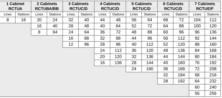
The number of CO lines and stations needed determine the size of the system. Tables 4-9 and
4-12 show the station and line capacities for eight-port RCOU/RCOS CO line PCBs.
There is a trade-off between stations and lines. Every group of eight stations installed decreases the CO line capacity of the system by eight, and vice versa. The exact hardware requirements depend on the features required.
The following table assumes one cabinet slot is used for an Optional Interface PCB.
Table 4-9 Strata DK424 Expansion Cabinet Configuration for Eight-Port CO Line PCBs Without Caller ID
1 Cabinet RCTUA
2 Cabinets RCTUB or RCTUBA/BB
3 Cabinets RCTUC/D
4 Cabinets RCTUC/D
5 Cabinets RCTUC/D
6 Cabinets RCTUC/D
7 Cabinets RCTUE/F
CO
Lines Stations CO
Lines Stations CO
Lines Stations CO
Lines Stations CO
Lines Stations CO
Lines Stations CO
Lines Stations
16 32 48 40 72 64 96 88 120 112 144 136 200 224
44 40 68 64 92 88 116 112 140 136 196 224
40 48 64 72 88 96 112 120 136 144 192 232
36 48 60 72 84 96 108 120 132 144 188 232
32 56 56 80 80 104 104 128 128 152 184 240
28 56 52 80 76 104 100 128 124 152 180 240
24 64 48 88 72 112 96 136 120 160 176 248
20 64 44 88 68 112 92 136 116 160 172 248
16 72 40 96 64 120 88 144 112 168 168 256
12 72 36 96 60 120 84 144 108 168 164 256
8 80 32 104 56 128 80 152 104 176 160 264
28 104 52 128 76 152 100 176 156 264
24 112 48 136 72 160 96 184 152 272
20 112 44 136 68 160 92 184 148 272
40 144 64 168 88 192 144 280
36 144 60 168 84 192 140 280
32 152 56 176 80 200 136 288
28 152 52 176 76 200 132 288
24 160 48 184 72 208 128 296
44 184 68 208 124 296
40 192 64 216 120 304
36 192 60 216 116 304
32 200 56 224 112 312
52 224 108 312
48 232 104 320
44 232 100 320
40 240 96 328
92 328
88 336
84 336
Print Version
C to D Update
DK424 Configuration System Capacity
Tables 4-10~4-12 assume one cabinet slot is used for an Optional Interface PCB.
Table 4-10 CO Loop Start Analog Lines with Caller ID Maximum Capacities
1 Cabinet RCTUA 2 Cabinets RCTUBA/BB 3 Cabinets RCTUC/D 4 Cabinets RCTUC/D 5 Cabinets RCTUC/D 6 Cabinets RCTUC/D 7 Cabinets RCTUE/F Lines Stations Lines Stations Lines Stations Lines Stations Lines Stations Lines Stations Lines Stations
8 24 24 40 40 56 56 72 72 88 88 104 136 152
16 56 32 72 48 88 64 104 80 120 128 168
8 72 24 88 40 104 56 120 72 136 120 184
16 104 32 120 48 136 64 152 112 200
24 136 40 152 56 168 104 216
32 168 48 184 96 232
40 200 88 248
80 264
Table 4-11 CO Ground Start with Caller ID, DID and/or Tie Analog Lines Maximum Combined Capacities
1 Cabinet RCTUA 2 Cabinets RCTUBA/BB 3 Cabinets RCTUC/D 4 Cabinets RCTUC/D 5 Cabinets RCTUC/D 6 Cabinets RCTUC/D 7 Cabinets RCTUE/F Lines Stations Lines Stations Lines Stations Lines Stations Lines Stations Lines Stations Lines Stations
8 16 20 24 32 40 44 48 56 64 68 72 104 112
16 40 28 48 40 64 52 72 64 88 100 120
8 64 24 64 36 72 48 88 60 96 96 136
16 88 32 88 44 96 56 112 92 144
12 96 28 96 40 112 52 120 88 160
24 112 36 120 48 136 84 168
20 120 32 136 44 144 80 184
16 136 28 144 40 160 76 192
24 160 36 168 72 208
32 184 68 216
28 192 64 232
60 240
56 256
Table 4-12 Digital, Tie, DID, Ground/Loop Start Digital T1 and ISDN PRI Lines Maximum Combined Capacities 2 Cabinets RCTUBA/BB 3 Cabinets RCTUC/D 4 Cabinets RCTUC/D 5 Cabinets RCTUC/D 6 Cabinets RCTUC/D 7 Cabinets RCTUE/F Lines Stations Lines Stations Lines Stations Lines Stations Lines Stations Lines Stations
48 56 72 88 112 112 120 152 144 144 192* 240
40 64 64 96 96 120 112 160 120 168 184 248
24 72 48 104 88 128 96 168 112 176 168 264
16 80 40 112 72 136 88 176 96 192 160 272
24 120 64 144 72 184 88 200 144 288
16 128 48 152 64 192 72 216 136 296
40 160 48 200 64 224 120 312
24 168 40 208 48 240 112 320
16 176 24 216 — — 96 336
* The maximum number of PRI lines for 2 cabinets is 47, 3~6 cabinets is 141 and 7 cabinets is 188. Notes
● T1 lines can be in increments of 8, 16 and/or 24.
● PRI channels can be in increments of 23B+1D or 47B + 1D. Each B-channel represents a PRI CO line.
Print Version
C to D Update
Tables 4-13~4-16 show system maximum capacity examples with ISDN BRI (S/T and/or U) circuits.
Table 4-13 RCTUA Maximum Capacity Examples with ISDN BRI (S/T and/or U-type) Circuits
BRI Station Circuits1
BRI Station B-Channels1
Other Station Circuits3
BRI Line Circuits4
BRI Line B-Channels4
Other Line Circuits5
82 162 16 0 0 0
6 12 16 2 4 0
5 10 16 3 6 0
4 8 16 42 82 0
4 8 16 2 4 4
3 6 16 1 2 8
2 4 24 2 4 8
1 2 28 1 2 12
Table 4-14 RCTUBA/BB Maximum Capacity Examples with ISDN BRI (S/T and/or U-type) Circuits
BRI Station Circuits1
BRI Station B-Channels1
Other Station Circuits3
BRI Line Circuits4
BRI Line B-Channels4
Other Line Circuits5
162 322 32 82 162 0
12 24 40 8 16 8
10 20 40 8 16 12
8 16 48 8 16 16
8 16 48 6 12 20
8 16 56 4 8 24
8 16 56 2 4 28
6 12 56 6 12 24
6 12 56 4 8 28
6 12 64 2 4 32
4 8 64 4 8 32
4 8 64 2 4 32
2 4 72 2 4 40
1. Each BRI circuit (S/T and/or U-type) provides two B-channels plus one D-channel and reduces the system capacity by two station ports and two CO lines. Each (S/T) BRI station circuit allows up to two TE-1 and TA devices to share the BRI B-channels (two simultaneous calls maximum per BRI circuit.). Each BRI-U circuit supports one TE-1 or TA device.
2. Maximum BRI capacity.
3. Other stations include Toshiba digital and electronic telephones, or attendant consoles, standard telephones and devices.
4. BRI S/T circuits are available with RBSU/RBSS PCBs and BRI-U circuits are available with RBUU/RBUS PCBs. ISDN BRI PCBs will be available with a future release of DK424 software. Each BRI line circuit (S/T or U) provides two BRI CO lines (B-channels) for incoming/outgoing calls.
5. Other lines include analog and digital (T1 or PRI) loop start, ground start, DID, and tie lines.
Print Version
C to D Update
DK424 Configuration System Capacity
Table 4-15 RCTUC/D Maximum Capacity Examples with ISDN BRI (S/T and/or U-type) Circuits
BRI Station Circuits1
BRI Station B-Channels1
Other Station Circuits3
BRI Line Circuits4
BRI Line B-Channels4
Other Line Circuits5
402 802 144 82 162 48
30 60 164 8 16 68
20 40 184 8 16 88
16 32 192 8 16 96
12 24 200 8 16 104
8 16 208 8 16 112
8 16 216 4 8 120
8 16 216 2 4 124
4 8 228 2 4 132
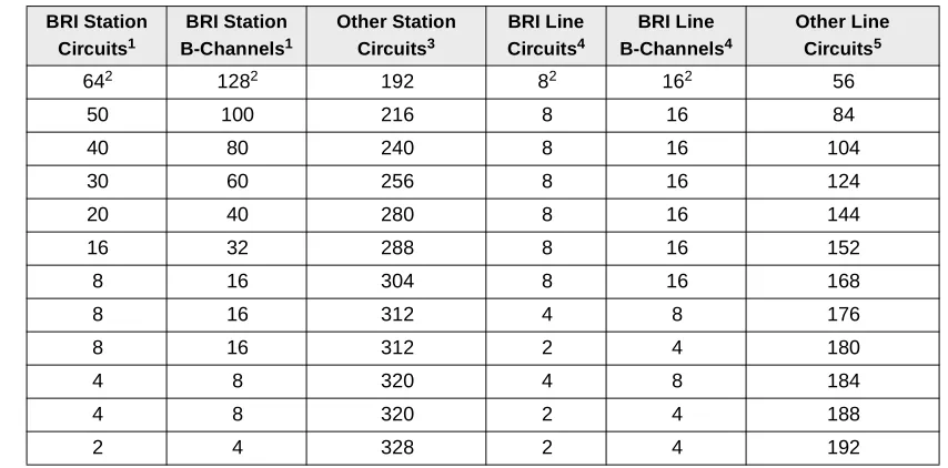
Table 4-16 RCTUE/F Maximum Capacity Examples with ISDN BRI (S/T and/or U-type) Circuits
BRI Station Circuits1
BRI Station B-Channels1
Other Station Circuits3
BRI Line Circuits4
BRI Line B-Channels4
Other Line Circuits5
642 1282 192 82 162 56
50 100 216 8 16 84
40 80 240 8 16 104
30 60 256 8 16 124
20 40 280 8 16 144
16 32 288 8 16 152
8 16 304 8 16 168
8 16 312 4 8 176
8 16 312 2 4 180
4 8 320 4 8 184
4 8 320 2 4 188
2 4 328 2 4 192
1. Each BRI circuit (S/T and/or U-type) provides two B-channels plus one D-channel and reduces the system capacity by two station ports and two CO lines. Each (S/T) BRI station circuit allows up to eight TE-1 and TA devices to share the BRI B-channels (two simultaneous calls maximum per BRI circuit.). Each BRI-U circuit supports one TE-1 or TA device.
2. Maximum BRI capacity
3. Conventional stations include Toshiba digital and electronic telephones, or attendant consoles, standard telephones and devices.
4. BRI S/T circuits are available with RBSU/RBSS PCBs and BRI-U circuits are available with RBUU/ RBUS PCBs. ISDN BRI PCBs will be available with a future release of DK424 software. Each BRI line circuit (S/T or U) provides two BRI CO lines (channels) for incoming/outgoing calls
5. Conventional lines include analog and digital (T1 or PRI) loop start, ground start, DID, and tie lines.
Print Version
C to D Update