Performance Analysis of Multihop Routing Protocol in
Wireless Sensor Networks
1Namita Sharma, 2 Parveen Kakkar
Research Scholar, M.Tech CSE, DAV Institute of Engg & Tech, Jalandhar, India Asst. Prof, Dept of CSE, DAV Institute of Engg & Tech, Jalandhar, India
Abstract: Wireless Sensor Networks are composed of small
sensor nodes deployed at random points in the network which need to be charged using batteries after some interval of time like laptops, wireless devices, mobile phones etc. Over the years many protocols have been developed and proposed by many researchers some have worked on the energy efficiency, some on power management while others on security and routing .But as every network has its own pros and cons , wireless sensor networks too have many issues which needs to be addressed with some strong remedial solutions like extending the lifetime is one of the main challenges nowadays. As the sensor nodes soon get drained out of energy after only few rounds of data transmission ,they need to be constantly charged which option is not always every time feasible. As the wireless sensor networks are finding many applications these days in various fields it is a dire need to propose a protocol which could extend the lifetime of wireless sensor networks using multi hop routing. In this paper, a new protocol is being proposed which will prolong the network lifetime of wireless sensor networks depending on the energy contained in them. It shows marked increase in the throughput as well as the energy efficiency of the network as the main task of data aggregation is not done by the cluster heads rather by the helper nodes. The simulation results show that in the homogeneous setup , multihop routing done between the sensor nodes arranged in various clusters based on concept of residual energy as well as data transmission at minimum distance helps to extend the network lifetime considerably as compared to contemporary protocols such as Assisted Leach protocol.
KEYWORDS:- single hop routing, LEACH, HEED, packet size variation, multihop routing, residual energy, Assisted Leach
I. INTRODUCTION
Wireless Sensor networks are composed of small sensor nodes deployed randomly in the network which need constant charging and soon get drained out of energy. The transmission of data from source to sink node in the wireless sensor networks over a prolonged period of time has been the main issue of wireless sensor nodes . One of the effective ways that have been devised is to increase the number of hops in the network over which the data packets would be transmitted and the results are quite astonishing. The targets of achieving the desired results is a bit easier in homogeneous networks but very difficult in heterogeneous networks.
Fig 1: Structure of WSN in LEACH Protocol [1]
II RELATED WORK
The need of the time is to develop more such routing protocols so that the network lifetime of the wireless sensor networks could be improved and that the network could survive for a longer duration.
LEACH protocol is basically a single hop protocol in which there is only one level of data transmission from source to destination .It works by making clusters of various sensor nodes which have their individual cluster heads .In this case in every cluster, those nodes are considered to be Cluster heads which have more amount of energy to transmit data from source to base station in every round[1]. For each round different node is chosen as the cluster head and the probability that it has not become the cluster head in the last 1/p rounds because the one which would have earlier been chosen as the cluster head would have expended most of its energy to transmit data from source to base station as this process drains out maximum energy from the node and thus for the next rounds, it is left with very less amount of energy and thus cannot act as cluster head as the main condition for any node to become cluster head is that it should be that node in the cluster which has maximum energy in it. The threshold in computed by formula:-
1
1
( mod )
( )
{
p
p
p
r
T n
=
− ∗
if n Ɛ G0 otherwise (1) [1]
Where p is the desired percentage of cluster heads , r is = the current round, and G is the set of nodes that have not been cluster heads in the last 1/p rounds
In case of LEACH protocol the sensor nodes are assumed to be scattered throughout the network and that all have same amount of initial energies. The clusters are formed by the cluster heads which are elected by the base station. The distance from the base station to all the sensor nodes is calculated depending on RSS[6] .Those nodes which have higher values of RSS are elected as cluster head nodes in the initial round and then these cluster head nodes broadcast “Hello” message to all the surrounding nodes in the network so that cluster formation could be done. The other sensor nodes which receive these messages calculate their distances from those cluster head nodes whichever cluster head nodes fall in closest possible or minimum distance from these nodes are responded to by them .The nodes which reply back to the cluster head nodes form small clusters with their individual cluster heads. After cluster formations have been done the sensor nodes are allocated set time frame slots in which they transfer data to the cluster head nodes and then they go to sleep. Further, the cluster head nodes perform the task of data aggregation and then finally they transmit the data to the base station in a single hop[7]. So no doubt, the speed and accuracy with
which the data transmission takes place in LEACH protocol is unmatched with similar other protocols, but it proves ineffective in extending the network lifetime after a certain time.
HEED[2] is also a single hop protocol but it does not consider the criteria of minimum distance for the selection of cluster heads for each round rather focuses on residual energy of all the nodes in the cluster at the end of each round. The node with the maximum residual energy in every cluster is selected as cluster head for the current round. Thus many such single hop routing protocols have been developed.
With the passage of time the need of multihop routing was felt which was supposed to increase the network lifetime as compared to the single hop routing protocols. The basic idea was that more would be the number of hops on which the data would be carried over before it reaches the base station, the more would be the extension of the time for which the networks would be active and functional[5]. Further, the caution is also to be kept while selecting the number of cluster heads nodes in the network as compared to the other sensor nodes in the cluster. The ideal value is 5 % for every 100 nodes in a network at a given time[3]. The other important point to be considered that the functions of data aggregation and calculation of the minimum distances from cluster heads to the base station should be divided between the various nodes other than the cluster heads in the higher levels of the protocol in the network like the helper nodes or gateway nodes so that cluster head nodes consume less energy as compared to the normal conditions for data transmission and thus are able to survive the network for longer duration of time especially in multihop routing so that the intended purpose is achieved.[4]
lifetime as compared to the single hop routing protocol.[11]
Yet another protocol named Assisted LEACH[3] focuses on network lifetime goes down when both data aggregation and routing are carried out by Cluster Heads alone which can be eradicated by usage of Helper Nodes for Routing and Cluster Heads for Data Aggregation. It reduced the overhead for route formulation to base station by electing next hop at each Helper Node using the Received Signal Strength values of beckon signal from base station already available at helper nodes during Helper Node Selection phase. The concept of Helper Nodes in Assisted LEACH (A-LEACH) protocol has improved the lifetime of the network by distributing the minimized energy dissipation throughout the nodes.
III PROPOSED SCHEME
The proposed scheme consists of assumptions , radio propagation model, algorithm which are discussed as:
A. Assumptions of proposed algorithm
1) It is assumed that N number of Sensor Nodes are scattered randomly over the network.
2) These nodes are Mobility and homogeneous in nature 3) Base station is far away from the network and is fixed. 4) Every sensor node is capable of communicating with every other sensor node and to the Base Station if needed.
5) The links are symmetric i.e. two nodes can communicate with the same power level.
6) Sensor nodes are deployed densely and randomly in sensor field.
7) All the nodes of the sensor network are equipped with same amount of energy level in the beginning. 8) There is mobility in sensor nodes.
B. Radio Energy Dissipation Model
For the proposed protocol, the first order radio model is used for energy dissipation in communication [15], where radio dissipates Eelec = 50 nano Joule / bit to drive the transmitter and the transmit- amplifier dissipates εelec =100
pico Joule/ bit/m2. To save energy, when required the radio can be turned on or off. Also the radio spends the minimum energy required to reach the destination. The energy consumed for data transmission of k bits packet is calculated from the Eq. (1).
E TX (k,d) = E elec * k + εelec * k*d 2 (2) [15]
and to receive this message, the radio expends energy is shown in Eq. (2):
E Rx (k) = E RX-elec (k) (3) [15]
Fig 2 : Radio Dissipation Model [15]
C. ALGORITHM
The main goal of the approach is to extend network lifetime of the network. For this reason, cluster head selection is mainly based on the residual energy of each node .The highest energy node that is if the remaining battery power is high then that node will become CH and the least mobility node will become a CH. Distance of a node from the cluster centroid. The BS calculates the distance of each node to its cluster centroid. The lesser distance node from the BS to itself will have the higher probability to become a CH.
1) Initialization Phase
The network initialization phase starts after the sensor nodes are randomly distributed in the application area. The base station broadcasts a “HELLO” message to all the nodes in the network to ensure that the network is alive.
2) Cluster Formation Phase
3) Cluster Head Selection Phase
After the clusters are formed, the Base station should decide whether or not the node becomes a cluster head for the current round. To find that, the value of energy are computed for all the nodes in the network for each round. The node which has highest residual energy is elected the cluster head for the specific round.
4) Data aggregation Phase:
Once the clusters are created and the CH issues a TDMA schedule to all the other sensor nodes in the clusters during which they need to transmit data to their Cluster heads.
5) Determination of helper nodes
Base Station constantly observes the residual energy and Mobility of the existing CH. If it is below the threshold value then it select another CH based on same conditions, described earlier. Finally the CH should be checked out the routing path. If the routing path residual energy goes below the threshold or any node fails, BS selects another path and sends the routing path to the respective CH. So, the base station calculated the distance of all nodes in the network to itself using RSSI value[16] which is calculated with the help of two ray ground model
P
r(d) =
2 2
* * *
4 *
t t r t r
P G G h h
d L (4) [16]
where
Pr: Power received at distance d
Pt: Transmitted signal power
Gt: Transmitter gain (1.0 for all antennas)
Gr: Receiver gain (1.0 for all antennas)
d: Distance from the transmitter L: Path loss (1.0 for all antennas)
ht: Transmitter antenna height (1.5 m for all antennas)
hr: Receiver antenna height (1.5 m for all antennas)
6) Data Transmission
The data aggregated by all the cluster heads are sent to the helper nodes. The helper nodes are those which have second highest energy left in them at the end of each round. Sometimes there might be a situation when there is no such helper node left inside the cluster as it too has been drained out of its energy so in that case the cluster head would search for some other available nearby helper node in some other cluster to which data can be transmitted. The cluster heads enter into sleep mode once they transmit data to the helper nodes so that their energies are saved. At a given time, all the cluster head nodes send data to the helper nodes using multihop routing. Further the helper
Fig 3 : Flowchart of the proposed algortihm
IV RESULT ANALYSIS AND DISCUSSION
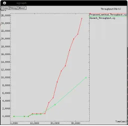
The simulation scenario consists of 49 sensor nodes deployed in the network field of size 1300m*1000 m in the wireless sensor network .The packet size is varied from 512 bytes. All the simulations have been performed using NS2.The results have been obtained at the end of seven rounds of the network at simulation time = 30 sec.The graphs show two lines one in red color and other in green color .The red line shows the results of the proposed protocol and the green line shows results of the Assisted LEACH protocol.
TABLE 1
SIMULATION PARAMETERS
simulator : Ns-2.35
simulation time : 30 sec
Channel Type: Wireless
No of nodes: 49
Topology: 1300m *1000m Radio Propagation model: Two way ground
Communication Model : Bi direction
Transmission Range: 250m
Interface Queue Type: Queue/Drop Tail/Pri Queue
Initial energy: 120 Joules
Antenna Type: Omni Antenna Link Layer : LL
Traffic Type: CBR
Packet Size: 512 bytes
PERFORMANCE METRICS
The performance analysis of the proposed protocol is done by comparing its results with the assisted LEACH Protocol which has been considered as the base protocol for the development of the proposed scheme by using some of the performance metrics such as:
• Average Energy
• Throughput
• Packet Delivery Ratio
• Packet Drop Rate
Average Energy Consumption ( Ea )
Let Ei = the initial energy level of a node, Ef = the final
energy level of a node and N = number of nodes in the simulation. Then
Ea =
) 1
(
n
ik fk k
E
E
N
−
=
∑
(5) [15]This metric is an important because the energy level of the network uses is proportional to the network’s lifetime. The lower the energy consumption the longer is the network’s lifespan. Thus the ideal value for average energy consumed by the protocol should be as less as possible otherwise if the protocol would consume more energy after every round then it would become difficult to increase the lifetime of the network . The exact formula for calculation of average energy is inbuilt in NS2.
Throughput: It is the measure[14] of the number of bits of data packets that are transmitted from source to destination in given time. It is always less than 1. The formula of measuring throughput is
Number of bytes received
Time in milliseconds (6)
Generally it is measured in Kb/sec or Bytes/sec. For the protocol aiming to enhance the throughput of the network , it is must that the packet drop rate, jitters , routing overheads and congestion or packet loss should be as less as possible otherwise lower value of throughput would decrease the data packets delivery from the source to the destination.
Packet Drop Rate: It is the measure of the number of packets dropped midway in the course of transmission from source to destination. It should be as less as possible for a protocol. It can be computed from the formula:
.
.
No of packets transmitted from source No of packets received at destination (7)
The packet drop rate should be as less as possible so that more and more data packets could be transmitted from source to the destination .For this effective data aggregation and routing techniques should be used.
Packet Delivery Ratio:It is the measure of the number of data packets correctly delivered from source to destination. It can be computed from the formula:-
Received packets
Received packets
+
Lost Packets
(8)This metric indicates both the loss ratio and the effort required to receive data of the routing protocol. If both the data are equal then the ratio should be equal to 1 which is
called as ideal ratio. If the ratio falls below the ideal ratio, then it could be an indication of some faults in the protocol. Conversely, if the ratio is higher than the ideal ratio, then it is an indication that the sink receives a more than number data packet which is called as redundant packets. It is not advantageous because receiving repeated packets will consume more energy.
Fig 4 : Graph showing comparison of two protocols based on Average Energy
Fig 5 : Graph showing comparison of two protocols based on Throughput.
If throughput is more it means that the routing overheads, packet drop and other kinds of delays concerned with routing the data packets is considerably less in the proposed protocol as compared to the Assisted LEACH .At the end of 30 seconds, the throughput of proposed protocol is 25 Kb/sec and that of the Assisted LEACH in 10 Kb/sec.
Fig 6 : Graph showing comparison of two protocols based on Packet Drop.
The graph clearly shows that after 35 seconds the packet drop rate
of the proposed protocol is almost 0 for the first few rounds and it would still be less after many such rounds as compared to the Assisted LEACH protocol due to variation in the techniques of working of both protocols.
Fig7: Graph showing comparison of two protocols based on PDR The graph clearly shows that after 35 seconds the Packet Delivery Ratio of the proposed protocol is almost 1 for the first few rounds and it would still be better after many such rounds as compared to the Assisted LEACH protocol whose value is 0.800 due to variation in the techniques of working of both protocols as concept of quick switching over to whichever helper node available improves the Packet delivery ratio for the proposed protocol.
TABLE 2 SUMMARY OF RESULTS
Name of Parameter Assisted LEACH Proposed Scheme
Average Energy 30 Joules 27 Joules Throughput 10 Kb/s 25 Kb/s
Packet Drop Rate 3 0
Packet Delivery Ratio 0.800 1.000
V. CONCLUSION
show that improvement is achieved not only in average residual energy but also in packet drop rate, packet delivery ratio and throughput. The proposed scheme enhances the network lifetime on the basis of average energy parameter than the assisted LEACH Protocol by 11%,Throughput by 15 units and PDR by 2 units hence the objective is achieved.
VI. FUTURE SCOPE
More efficient protocols need to be developed so that the problem of extension of network lifetime could be resolved effectively for them. Thus working on such similar concepts many such effective protocols as well as algorithms could be developed in future especially taking into consideration the heterogeneous environment. Apart from it the proposed scheme could be run on other traffic class like HTTP,VBR , VOIP etc and the results can be evaluated on other performance metrics. The bandwidth can be increased as well as other issues like reducing packet drop rate, reducing other routing overheads would also show improvement in results.
REFERENCES
[1] Wendi B. Heinzelman, Member, IEEE, Anantha P. Chandrakasan, Senior Member, IEEE, and Hari Balakrishnan, Member, IEEE,” An Application-Specific Protocol Architecture for Wireless Microsensor Networks”, 660 IEEE TRANSACTIONS ON WIRELESS COMMUNICATIONS, VOL. 1, NO. 4, OCTOBER 2002.
[2] Amir Akhavan Kharazian1, Kamal Jamshidi and Mohammad Reza Khayyambashi ,"ADAPTIVE CLUSTERING IN WIRELESS SENSOR NETWORK: CONSIDERING NODES WITH LOWEST ENERGY", International Journal of Ad hoc, Sensor & Ubiquitous Computing (IJASUC) Vol.3, No.2, April 2012
[3] Sunkara Vinodh Kumar and Ajit Pal, " Assisted-Leach (A-Leach) Energy Efficient Routing Protocol for Wireless Sensor Networks", International Journal of Computer and Communication Engineering, Vol. 2, No. 4, July 2013.
[4] J.Gnanambigai,Dr.N.Rengarajan,K.Anbukkarasi, “Leach and Its Descendant Protocols: A Survey”, International Journal of Communication and Computer Technologies Volume 01 – No.3, Issue: 02 September 2012 ISSN NUMBER : 2278-9723
[5] K. Padmanabhan, P. Kamalakkannan, “A Study on Energy Efficient Routing Protocols in Wireless Sensor Networks”, European Journal of Scientific Research ISSN 1450-216X Vol.60 No.4 (2011), pp. 499-511
[6]K S Shivaprakasha, Muralidhar Kulkarni,” Energy Efficient Society, Shortest Path Routing Protocol for Wireless Sensor Networks”, IEEE Computer 978-0-7695-4587-5/11 $26.00 © 2011 IEEE
[7] Yu Hu, Xiaorui Shen, Zhenhua Kang,” Energy-Efficient Cluster Head Selection in Clustering Routing for Wireless Sensor Networks”,978-1-4244-3693-4/09/$25.00 ©2009 IEEE
[8] Wendi Rabiner Heinzelman, Anantha Chandrakasan, and Hari Balakrishnan,” Energy-Efficient Communication Protocol for Wireless Microsensor Networks”, 0-7695-0493-0/00 $10.00 (c) 2000 IEEE
[9]S.Koteswararao,M.Sailaja,T.Madhu,“Implementation of Multi-hop Cluster based Routing Protocol for Wireless Sensor Networks ", International Journal of Computer Applications (0975 – 8887) Volume 59– No.8, December 2012
[10] S. Taruna, Rekha Kumawat, G.N.Purohit," Multi-Hop Clustering Protocol using Gateway Nodes in Wireless Sensor Network International Journal of Wireless & Mobile Networks (IJWMN) Vol 4 No 4,August 2012
[11] Raj Kumar , Dr. Mukesh Kumar, " LEACH: Features, Current Developments, Issues and Analysis “International Journal of Computer Science and Communication Engineering,Volume1,Issue1,October 2012.
[12] Dali Wei, Yichao Jin, Serdar Vural, Klaus Moessner and Rahim Tafazolli, “An Energy-Efficient Clustering Solution for Wireless Sensor Networks”, IEEE TRANSACTIONS ON WIRELESS COMMUNICATIONS, VOL. 10, NO. 11, NOVEMBER 2011, 1536-1276/11$25.00 ⃝c 2011 IEEE.
[13] Nitika Vats Doohan, Durgesh Kumar Mishra Sanjiv Tokekat,”SHORTEST PATH ROUTING PROTOCOL (SPRP) FOR HIGHLY DATA CENTRIC WIRELESS SENSOR NETWORKS”, 978-1-4577-1088-9/11/$26.00 ©2011 IEEE.
[14] Wazir Zada Khan, N.M. Saad, Mohammed Y Aalsalem, “An Overview of Routing Metrics for the Evaluation of Routing Protocols in Wireless Sensor Networks”, European Journal of Scientific Research ISSN 1450-216X Vol.79 No.2 (2012), pp.208-224
15] R.U. Anitha,Dr. P.Kamalakannan, “Enhanced Cluster Based Routing Protocol in Wireless Sensor Networks”, International Conference on Pattern Recognition,Information and Mobile Engineering,Feb 21-2,2013