Compensating Voltage Sag Using 5-Level Flying
Capacitor Multi Level Inverter Based DVR
R.T.Padagalinngam
M.E. Power Management, Regional centre of Anna University, Madurai.
Abstract: This paper presents the application of dynamic voltage restorers (DVR) on power distribution systems for mitigation of voltage sags, harmonics and imbalances at sensitive loads. The dynamic voltage restorer (DVR) has become popular as a cost effective solution for the protection of sensitive loads from voltage sags and swells. It would be advantageous that a DVR could also be used to compensate any steady state load voltage harmonics, since this would increase the Power Quality. The DVR, which is based on a five-level flying-capacitor voltage Source inverter (VSC), has been proved suitable for the task of compensating voltage disturbance. The performance of the DVR depends on control technique involved. This paper presents the control system based on the so-called repetitive control.
Unlike other control schemes with a comparable range of applicability, only one controller is needed to cancel out all three disturbances simultaneously, while
exhibiting good dynamic performance. Simulation results are presented to illustrate and understand the performances of DVR in supporting load voltage. To evaluate the quality of the load voltage during the operation of DVR, Total Harmonic Distortion (THD) is calculated.
Keywords:
Dynamic voltage restorer (DVR), Flying Capacitor multilevel inverter, power quality (PQ), repetitive control, voltage sags,MATLAB- SIMULINK.
I. INTRODUCTION
POWER quality (PQ) has become an important issue over the past two decades due to the relentless integration of sensitive loads in electrical power systems, the disturbances introduced by nonlinear loads, and the rapid growth of renewable energy sources. Arguably, the most common PQ disturbance in a power system is voltage sags , but other disturbances,
such as harmonic voltages and voltage imbalances, may also affect end user and utility equipment leading to production downtime and, in some cases, equipment terminal damage.The dynamic voltage restorer (DVR) is one of the most efficient and economic devices to compensate voltage sags . The DVR is basically a voltage-source converter in series with the ac grid via an interfacing transformer, conceived to mitigate voltage sags and swells. For low-voltage applications, DVRs based on two-level inverters are normally used and, therefore, much of the published literature on DVRs deals with this kind of converter. Nevertheless, for higher power applications, power-electronic devices are usually connected to the Medium-voltage (MV) grid the use of two-level voltage converters becomes difficult to justify owing to the high voltages that the switches must block.
applications can be found in.Research work has been reported on several DVR multilevel topologies, but so far, no work seems to have been published on DVR’s by using FC multilevel inverters.This paper focuses on the design of a closed-loop control system for a DVR by using a five-level flying capacitor converter, based on the so-called repetitive control. Repetitive control was originally applied to eliminate speed fluctuations in electric motors but it has also been successfully used in power-electronics applications, such as power-factor control in three-phase rectifiers and active-filter control.
The control system presented in this paper has a wide range of applicability. It is used in a DVR system to eliminate voltage sags, harmonic voltages, and voltage imbalances within a band- width. Unlike other control schemes with a comparable range of applicability, only one controller is needed to cancel out all three disturbances simultaneously, while exhibiting good dynamic performance. On the one hand, a closed-loop controller, which consists of a feedback of the load voltage and the repetitive controller, guarantees zero tracking error in steady state. On the other hand, the applied control strategy for the voltage balancing of the flying capacitors, along with a feed forward term of the grid voltage and a controller for the output voltage of the DVR filter, provides excellent transient response.This paper is organized as follows. The model of a five-level flying-capacitor DVR is presented in Section II. The complete control-scheme structure is studied in Section III, including the three different control subsystems, namely, the filter output voltage controller, the repetitive control structure for the load voltage, and the flying-capacitor voltage regulator scheme, as well as the modulation method used to operate the multilevel converter. Simulation results obtained by implementing the control system and the five-level flying-capacitor DVR in MATLAB are presented in Section IV. Finally, the main conclusions are given in Section V.
II. CONFIGURATION OF THE DVR
A. Five-Level FC
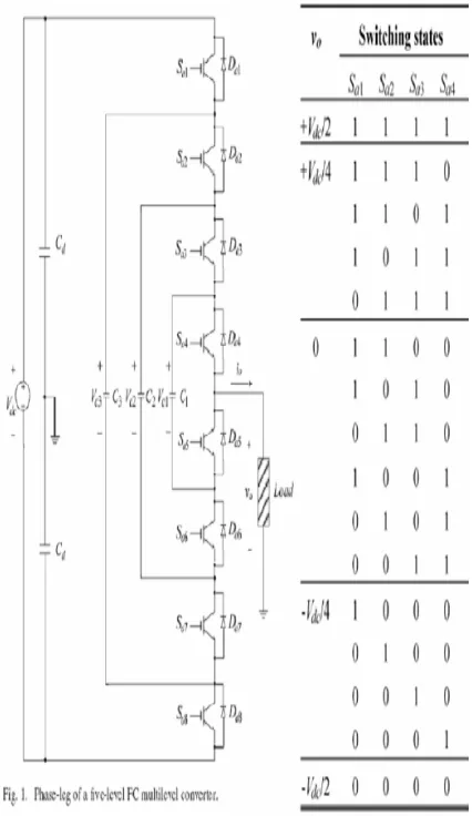
Fig. 1 shows a phase leg of a five-level flying-capacitor converter, each phase leg has the same structure in three-phase converters, and the flying capacitors of one phase are independent from those of the other phases. One advantage of the flying capacitor multilevel converter topology is that the extension to converters with more than three levels is easier than in the
neutral-point-clamped option Nevertheless, the number of capacitors becomes excessive as the number of levels increases.
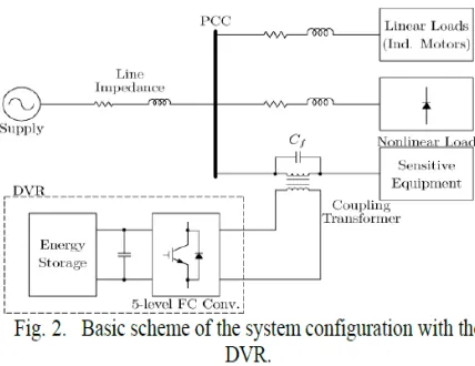
B. DVR Connection System
The location of the DVR placed between the grid and the sensitive equipment is shown in Fig. 2. Different kinds of loads are assumed to be connected to the point of common coupling (PCC), such as linear loads (e.g., induction motors), nonlinear loads, and sensitive equipment. The DVR consists of a five-level flying-capacitor voltage-source converter and energy storage which provides the necessary voltage to the dc link. The series connection of the DVR is achieved by means of a coupling transformer. A passive filter has been used to filter out the high harmonics generated by the PWM process
The equivalent circuit for the one-line system in Fig. 2 is depicted in Fig. 3, where vs is the supply voltage, models the line impedance, is the current injected by the supply, which splits at the PCC into the current flowing through the sensitive equipment i (this current is divided into the current through the coupling transformer and the current through the filter capacitor ), and the current injected into the loads . The voltage Vpcc is the measured voltage at the PCC, u stands for
the DVR voltage which has been modeled as an ideal voltage source, the parameters R and L are the resistance and the leakage inductance, respectively, of the coupling trans- former whereas is the capacitor used together with the coupling-transformer leakage inductance to filter out the high-frequency harmonics. Finally, uc and v are the voltages across the filter capacitor and the measured voltage across the sensitive equipment, respectively.
The equation of the sensitive-equipment v oltage can be written as
with the following state-variable model for the coupling trans- former and the capacitor set:
where the state variables are and , the control input is and is a disturbance input.
III. CONTROL SYSTEM AND MODULATION STRATEGY
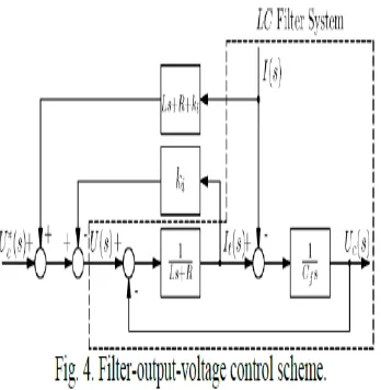
A. Control System for the Output Voltage of the LC Filter
System (2) is a second-order filter with natural frequency and damping coefficient = . . This filter exhibits a large resonance since the resistance R usually has a very small value and, therefore, the damping coefficient is also very small. To overcome this problem, closed-loop control of the filter output voltage is required. A proportional state-feedback controller plus a feed forward term are proposed for (2), with the following structure:
Where K is the feedback-gain matrix, uc*(t) is the reference value, and the feed forward term
a second-order closed-loop system with natural frequency and damping coefficient =1, which means that the closed-loop system has two identical real poles equal to and the time response will not exhibit any over shoot. Furthermore, as will be shown in Section IV, this design implies that the gain is ku equal to zero and, hence, there is no need to feed back the capacitor voltage.
In order to obtain the function h(i(t)), the Laplace transform is applied to (2) and (3), yielding
and H(s) is chosen so that the term I(s) has no effect in the capacitor voltage, which implies that
H(s) = Ls +R+ ki and h(i(t)) = Ldi/dt + (R + ki)i(t).
The structure of this control scheme can be seen in Fig. 4.
B. Load-Voltage Control Scheme
The control system developed in the previous section requires further development since it may be not able to guarantee a perfect compensation of the load voltage for every situation. In order to counteract possible disturbances which can affect the load voltage, an outer closed-loop control system is required. The control scheme proposed in this paper uses a feed forward term of the voltage at the PCC to improve the transient response and a feedback term of the load voltage to guarantee zero error in steady state against disturbances.
voltage closed-loop control scheme including the regulator for the filter output voltage
Fig. 5 shows the complete continuous-time control system for the load voltage. Assuming that there are no modeling errors and neglecting any delay in the control system, the DVR can be seen as an ideal linear amplifier (see [24]). The coupling transformer, together with the capacitor
Cf, has been included in the figure as well as the detailed control system for the filter output voltage. The input V*(S) is the set point for the load voltage V(s), U(s) is the DVR voltage, and Vpcc(s) is the supply voltage. Recalling that (5) Then, the load voltage can be calculated as (6)With (7) (8) In order to illustrate the main features of the repetitive control, a basic transfer function of the controller R(s) is proposed as (9) Where w1 is the fundamental frequency of the supply voltage.
C. Phase-Shifted Pulse width Modulation
harmonic voltages, although it exhibits a higher power loss than the SHE-PWM due to the higher switching frequency of the converter. In this paper, the well-known phase-shifted PWM method has been used since its implementation is simple and provides a certain degree of flying-capacitor voltage balance [7].
In a scheme with an n-level converter, n-1 triangular carriers with frequency fc have to be compared with a common sinusoidal modulating signal with frequency fm [27]. It is assumed that the carrier frequency is high enough to consider the modulating signal as a constant value in a period of the carrier. The switching instants are determined by the intersection between the
modulating signal and the different carriers. A shifting phase of 2Π/(n- 1) is introduced in each carrier, which ensures an effective switching frequency of (n-1) fc and improves the total harmonic distortion of the output voltage, while the frequency modulation ratio yields mf = (n-1) fc / fm. For the three-phase case, three modulating signals with a shifting phase of 120 are used. There are four regions in terms of the value of m shown in Fig. 6(a)–(d), respectively. The control switching signals g1, g2, g3, and g4
for the main switches of Sa1 to Sa2 as well as switching states and associated capacitor charging and discharging modes .
IV Simulation Results
Fig represents the load voltage, input voltage(pu), injected voltage(pu), output current(pu) and external load voltage without DVR(pu) obtained through MATLAB simulation. The closed loop control of voltage swell compensation in a DVR system is shown in the Fig. 5.3. Initially the system was subjected to voltage
V. CONCLUSION
Nowadays, reliability and quality of electric power is one of the most discuss topics in power industry, there are numerous types of power quality issues and power problems Among them, two power quality problems have been identified to be of major concern to the customers are voltage sags and harmonics, but this project is focusing on voltage sags. Voltage sags are huge problems for many industries, and it is probably the
most pressing power quality problem today.In this paper DVR based on a five level flying-capacitor converter operated by a repetitive-control scheme. This repetitive-control structure simultaneously cancels out voltage sags, voltage imbalances, and voltage harmonics other than high-frequency switching harmonics. The control system is split into three subsystems: the first one works to eliminate the resonance peak of the filter used in the converter output voltage; while the second one is the repetitive control, which ensures a fast transient response and zero-tracking error in steady-state for any sinusoidal reference and for any sinusoidal disturbance whose frequencies are an integer multiple of the fundamental frequency. Finally, the third subsystem maintains constant, balanced voltages in the flying capacitors.
The control system, together with the DVR, has been implemented in MATLAB Comprehensive simulation results using an MV test system show the DVR’s excellent performance and the control system in order to protect sensitive equipment from PQ disturbances.
REFERENCES:
1.Ahmed M. Massoud, Member, IEEE, Shehab Ahmed, Member, IEEE, Prasad N. Enjeti,
Fellow, IEEE, and Barry W. Williams ” Evaluation of a Multilevel Cascaded-Type Dynamic Voltage Restorer Employing Discontinuous Space Vector Modulation”. IEEE TRANSACTIONS ON INDUSTRIAL ELECTRONICS, VOL. 57, NO. 7, JULY 2010.
2.H.K.Al-Hadidi,Student Member, IEEE, A. M. Gole, Senior Member, IEEE,and David A. Jacobson, Senior Member, IEEE. "Minimum Power Operation of cascade Inverter-Based Dynamic Voltage Restorer”. IEEE TRANSACTIONS ON POWER DELIVERY, VOL. 23, NO. 2, APRIL 2008.
3.J. Dionísio Barros, Member, IEEE, and J. Fernando Silva, Senior Member, IEEE .”Multilevel Optimal Predictive Dynamic Voltage Restorer”. IEEE TRANSACTIONS ON INDUSTRIAL ELECTRONICS, VOL. 57, NO. 8, AUGUST 2010.
4. Carl Ngai-man Ho, Member, IEEE, Henry S. H. Chung, Senior Member, IEEE, and Keith T. K. Au.” Design and Implementation of a Fast Dynamic Control Scheme for Capacitor-Supported Dynamic Voltage Restorers”. IEEE TRANSACTIONS ON POWER ELECTRONICS, VOL. 23, NO. 1, JANUARY 2008.
5.Pedro Roncero-Sánchez, Member, IEEE, and Enrique Acha, Senior Member, IEEE.” Dynamic Voltage Restorer Based on Flying Capacitor Multilevel inverters Operated by Repetitive Control”. IEEE TRANSACTIONS ON POWER DELIVERY, VOL. 24, NO. 2, APRIL 2009
6.K.N.V. Prasad, G. Ranjith kumar, Y.S. Anil kumar, G. Satya narayana IEEE Member, “Realization of Cascaded H-Bridge5-Level Multilevel Inverter as Dynamic Voltage Restorer”. 2013 International Conference on Computer Communication and Informatics (ICCCI -2013), Jan. 04 – 06, 2013, Coimbatore, INDIA.
7.Christoph Meyer, Christoph Rolm-auLs, Rik W. DcDoncker. “Five Level Neutral-Point Clamped Inverter for a Dynamic Voltage Restorer”. EPE 2005-Dresden- ISBN :90-75815-08-5-P.1.
8.E. Acha, V. G. Agelidis, O. Anaya, and T. J. E. Miller, Power Electronic Control in Electrical Systems. Oxford, U.K.: Newnes, 2001.
9. C. Feng, J. Liang, and V. G. Agelidis, “Modified phase-shifted pwm control for flying capacitor multilevel converters,” IEEE Trans. Power Electron., vol. 22, no. 1, pp. 178–185, Jan. 2007.
10. J. Arrillaga, Y. H. Liu, and N. R.Watson, Flexible Power Transmission. The HVDC Options. Chichester, U.K.: Wiley, 2007.