ISSN (online): 2349-784X
Effect of R. C. Shear Wall Position on Parameters
of R. C. Multistorey Frame
Sachdeva Gourav Jain Rajesh
M.E Scholar Associate Professor Department of Structure Engineering Department of Civil Engineering
Jabalpur Engineering College, Jabalpur
Jabalpur Engineering College, Jabalpur
Chandak Rajeev
Professor
Department of Civil Engineering Jabalpur Engineering College,
Jabalpur
Abstract
Shear walls are like vertically-oriented wide beams that carry earthquake loads downwards to the foundation. These loads are produced in the plane of the wall. In this work, a G+5 storey R.C. building frame has been considered and analyzed for seismic zone-lll using staad pro. v8i (series 4) package, special moment resisting frame (SMRF) and hard rock types are also used in this work. Storey drift, design axial force, design shear force and design bending moment are some parameters taken to compare the results for different models. It is clear to conclude that the model-IV is most effective one.
Keywords: Shear Wall, Staad Pro. V8i (Series 4), SMRF, Storey Drift, Maximum Shear Force And Maximum Bending Moment And Total Weight Of Reinforcement.
________________________________________________________________________________________________________
I.
I
NTRODUCTIONEarthquake may occur on land or sea, at any place on the surface of the earth where there is a major fault. In this work the main focus is to analyze an R.C. structure using code IS 13920-1993 for ductile detailing. The code used for earthquake loadings is IS 1893- 2002. In last 2-3 decades, the use of shear walls has been increased to such an extent that the stiffness of the building fulfills all the requirements. However the use of shear walls is limited. Reinforced concrete multi-storeyed buildings in india, for the first time, have been subjected to a strong ground motion shaking in bhuj earthquake ( January 26, 2001). It has been observed that the principal reasons of failure may be accounted to lack of stiffness, faulty construction practices, mass irregularity and floating columns etc. In this work shear wall is provided symmetrically and the building frame considered is also symmetrical.
II.
L
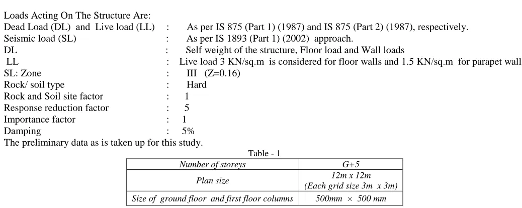
OADING CONSIDERATIONLoads Acting On The Structure Are:
Dead Load (DL) and Live load (LL) : As per IS 875 (Part 1) (1987) and IS 875 (Part 2) (1987), respectively. Seismic load (SL) : As per IS 1893 (Part 1) (2002) approach.
DL : Self weight of the structure, Floor load and Wall loads
LL : Live load 3 KN/sq.m is considered for floor walls and 1.5 KN/sq.m for parapet wall. SL: Zone : III (Z=0.16)
Size of 2nd, 3rd , 4th & 5th floor column 400mm × 400 mm
Size of beams 300mm × 230 mm
Wall thickness thick including Plaster 230mm
Shear wall thickness 200 mm
Depth of slab 125 mm
Ground storey height From Foundation 3.0m
Total height 18m
Floor to floor height 3.0m
Grade of Concrete and steel M30 and Fe 415
Ductility design IS: 13920-1993
Support condition Fixed
III.
L
ITERATURE REVIEWA lot of research work has been done in the direction of shear wall multistory building. Arvind Vinayakrao Achole(2006), Dr. G.N. Ronghe(2006) [1] studied the behavior of building frame with steel plate shear walls. Ashis Debashis Behera ,K.C. Biswal [2] studied 3-D analysis of building frame using staad pro. Dr. Sudhir K. Jain and Dr. R.K. Ingle [4] gave notes on the explanatory examples for ductile detailing of R.C. building. They explained the ductile detailing thoroughly. Anand N., Mightraj, C.Prince Arulraj, G.(2010) [3] presented the Seismic Behaviour of RCC Shear Wall Under Different Soil Conditions. However the study related to shear wall effect has not been yet done much.
IV.
O
BJECTIVE OF STUDY1) To understand the purpose of using shear walls using staad pro. through this work. 2) To analyze an R.C. building frame using staad pro. Software setup.
3) To judge the effect of an R.C. shear walls on an R.C. building when provided at different locations. 4) To study the results of Storey drift, maximum shear force and maximum bending moment.
5) To know the best location of shear wall for parameters considered.
V.
M
ETHODOLOGYSteps to model and analyze the R.C.C. building frame. Firstly go to run structure wizard and select bay frame. Then follow the following steps given below,
It consists of 2 steps which are: 1) Modeling:
2) Post – processing:
VI.
P
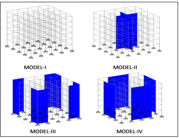
ROBLEM STATEMENT(IJSTE/ Volume 2 / Issue 4 / 014)
Fig 2: Elevations of Models Considered
VII.
R
ESULT AND GRAPHSStorey Drift: A.
Along X-Direction: 1)
Table – 2 STOREY DRIFT (cm)
Storey No. Model- l Model- ll Model- lll Model- lV
1(G.F.)
0 0 0.0003 0.0002
2 0.0418 0.0027 0.0019 0.0019
3 0.0856 0.0076 0.0039 0.0034
4 0.1104 0.0139 0.0063 0.0047
5 0.1036 0.0194 0.0083 0.0052
6 0.0804 0.0228 0.0094 0.005
7 0.0497 0.0233 0.0094 0.0044
1(G.F.)
0 0 0.0003 0.0002
2 0.0418 0.0027 0.0019 0.0019
3 0.0856 0.0076 0.0039 0.0034
4 0.1104 0.0139 0.0063 0.0047
5 0.1036 0.0194 0.0083 0.0052
6 0.0804 0.0228 0.0094 0.005
7 0.0497 0.0233 0.0094 0.0044
PERCENTAGES OF MAXIMUM STOREY DRIFT OF INDIVIDUAL MODELS W.R.T. MODEL-I -78.894% -91.48% -95.289%
Fig. 4
Maximum Shear Force & Maximum Bending Moment: B.
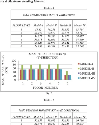
Table – 4
MAX. SHEAR FORCE (KN) (Y-DIRECTION)
FLOOR LEVEL Model- l Model- ll Model- lll Model- lV
1 53.82 76.251 53.832 53.714
2 54.470 77.677 54.516 54.141
3 54.877 79.580 54.975 54.427
4 55.618 81.034 55.756 54.869
5 55.947 81.877 56.134 55.292
6 24.995 46.501 25.132 23.748
Fig. 5
Table – 5
MAX. BENDING MOMENT (KN-m) (Z-DIRECTION)
FLOOR LEVEL Model- l Model- ll Model- lll Model- lV
1 30.155 38.602 30.156 30.116
(IJSTE/ Volume 2 / Issue 4 / 014)
3 31.484 43.667 31.522 30.884
4 32.572 45.860 32.762 31.505
5 33.017 47.112 33.275 32.184
6 16.703 29.573 16.917 14.452
Fig. 6
Total Weight of Reinforcement: For Beams and Column: C.
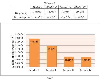
Table – 6
Weight (N)
Model- l Model- ll Model- lll Model- lV
119581 115661 109497 109381
Percentages w.r.t. model-l -3.278% -8.432% -8.5297%
Fig. 7
Note:
1) Minus (-) sign shows decreasing percentages. 2) Plus(+) sign shows increasing percentages
VIII.
D
ISCUSSIONS&
RESULTS2)
Maximum Shear Force & maximum bending moment:The maximum shear force was found in each model for all floor levels and the least value is found for model-lV among all four models. The value of maximum shear force for model-lV is 55.292KN. similarly the maximum bending moment was also found in each model for all floor levels and the least value is found for model-lV among all four models. The value of maximum bending moment for model-lV is 32.184 KNm.
As per [3], the bending moment increases as storey no. increases and the same results are found in this work and then suddenly minimizes at top storey.
As noticed in [1], the bending moment are found to be increases as the no. of storey increases except ground floor because just on the first storey bending moment found to be decreased and then increased continuously. Here, in this work, the bending moment increases gradually with increase in storey no. and then suddenly decreases at top storey.
3) Total weight of reinforcement:
It is found that the least value of total weight of reinforcement was for model- lV i.e., 109381 N.
IX.
C
ONCLUSIONThe behavior of a R.C. building was analyzed with shear wall at different locations and conclusion may be drawn from this study.
1) Storey Drift :The least storey drift in each, x & z direction is to be found for model IV and the maximum storey drift for model-IV is found at storey 5th .
2) Maximum Shear Force & maximum bending moment : The maximum shear force was found in each model for all floor levels and the least value was found for model-lV among all four models and the maximum shear force for model-IV is found at storey 5th .
The maximum bending moment was found in each model for all floor levels and the least value was found for model-lV among all four models and the maximum bending moment for model-IV is found at storey 5th .
3) Total weight of reinforcement : The total weight of reinforcement for beam and columns is found least for model-lV. 4) Analysis using software makes the structure as designer likes.
5) Structure can be compared and designed easily by using staad pro. and can be used to investigate the structure for strength & economy points of profit.
Therefore the overall conclusion is sheding light toward the model-lV that it is the most effective location among all other locations.
R
EFERENCES[1] Arvind Vinayakrao Achole, Dr. G.N. Ronghe “ Behaviour of building frames with steel plate shear walls “ VNIT NAGPUR(2006)
[2] Ashis Debashis Behera, K.C. Biswal ”3D Analysis of building frame using Staad Pro.” NIT ROURKELA
[3] Anand, N, Mightraj, C.Prince Arulraj, G. “Seismic Behaviour of RCC Shear Wall Under Different Soil Conditions” IGS Mumbai &
IIT Bombay,(2010)
[4] Dr. Sudhir K Jain (IIT Kanpur) and Dr. R.K. Ingle (VNIT, Nagpur) “ Explanatory Examples for Ductile Detailing of RC Building”
IITK-GSDMA-EQ22-V3.0
[5] Dr. Sudhir K Jain (IIT Kanpur) and Dr. H.J.Shah (M.S.University of Baroda, Vadodara) “Design Example of a Six Storey Building”
IITK-GSDMA-EQ26-V3.0
[6] Alfa Rasikan, M. G. Rajendran “Wind behaviour of buildings with and without shear wall” IJERA, Vol. 3, Issue 2, March -April 2013, pp.480-485
[7] Krishnaraj R. Chavan, H.S.Jadhav“Seismic Response of R.C. Building with Different Arrangement of Steel Bracing System”
IJERA,Vol. 4 Issue7, pp. 218-222
[8] IS: 1893-2002 (part-1) “criteria for earthquake resistant design of structures” fifth revision, Bureau of Indian Standards, New Delhi.
[9] IS: 875-1987 (part-2) for Live Loads or Imposed Loads, code practice of Design loads (other than earthquake) for buildings and structures
[10] Is :13920-1993 (reaffirmed 2003) for ductile detailing of reimfforced concrete structures subjected to seismic forces, third print, New Delhi,India.
[11] P.C.Varghese, “Advanced Reinforced Concrete Design”, Second Edition.