Induction Motor Protection using Micro
Controller
Helly M. Chudasama Praful Ranava
Assistant Professor Assistant Professor
Department of Electrical Engineering Department of Electrical Engineering
DSTC - Junagadh DSTC - Junagadh
Vimal V Tank Bhavik J Parmar
Assistant Professor P.G Student
Department of Electrical Engineering Department of Electrical Engineering
DSTC - Junagadh Nirma University- ABD
Abstract
Main aim of this paper is to protect the three phase Induction motors from various faults using microcontroller. The circuit will take the full control of the motor and it will protect the motor from several faults such us over voltage and under voltage and the circuit will switch on the motor under safety conditions. This also protects induction motor from single phasing which is also a major fault. The circuit was fully controlled by the microcontroller and the microcontroller will continuously monitors the voltages of the three phases and if the voltage goes abnormal then it will switch off the motor until they are normal.
Keywords: Microcontroller, over and under voltage protection, single phasing protection
________________________________________________________________________________________________________
I. INTRODUCTION
Using microcontroller, we can able to start and stop the three phase Induction motor automatically and the circuit will take full control of the motor and it will protect the motor from several faults such as over voltage and under voltage and the circuit will switch on the motor under safety conditions. This also protects Induction motor from single phasing which is also a major fault. It is not only protecting motor from transient voltages, it also switch on the motor automatically when power comes without manual requirement and off the motor after predetermined time.
This motor is manually monitoring is difficult at the time of fault so automatic protection of induction motor has such an importance. Here dual comparator to compare over/under voltages with the present voltage and send signal to microcontroller if the voltage goes beyond the range is used.
Here we are also using LM393 dual comparator. Addition to this we are using two switches one for auto on and another one for auto off. Here the motor will run automatically when auto on is set and it will start the motor automatically after a particular time if off is set.
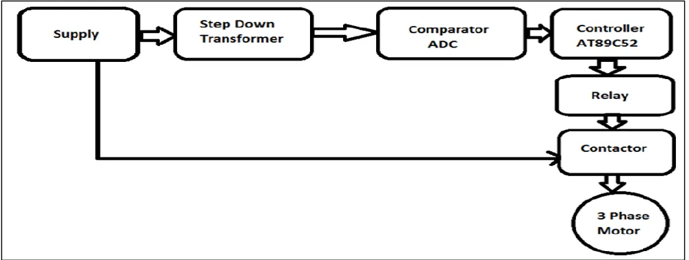
The main block diagram of automatic voltage control of Induction motor using microcontroller is shown in fig:
Fig. 2: Block diagram
II. WORKING PRINCIPLE
that once the auto on switch is set and if the supply is provided and also voltages are in normal condition then the motor start automatically.
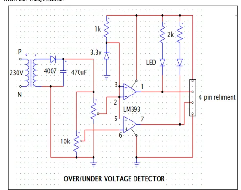
Over/Under Voltage Detector:
Fig. 3: Over/Under Voltage Detector
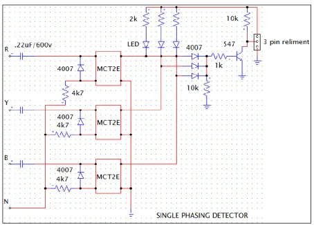
Single Phasing Detector:
Fig. 4: Single phasing Detector
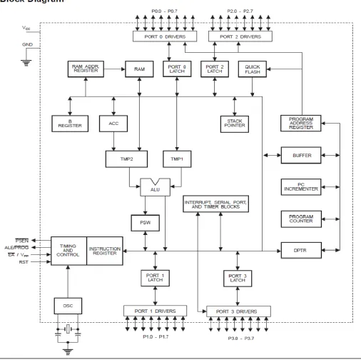
The Main Controller Section:
This is the main section of the entire circuit. The controller used here is the 89s52 from Atmel. The controller is based on the very famous 8051 core. The basic 8051 had a 4kB rom and a 128 byte RAM. The 52 chip which is an advanced version of the earlier one has 8kB of ROM and 256 byte of RAM. It also has an extra timer. Being an s device is supports faster clock frequencies than the c devices and is an ISP (in system programmable) chip owing to its 5V programming voltage as compared to the 12V on the C devices. Here it has been connected in a standard fashion with pins 40 and 20 being the positive and negative supply respectively. The programming voltage pin (31) has also been connected to the +Vcc. The clock generator crystal is connected between the pin 18 and 19 of the controller. Two 22pf capacitors are connected to the pins of crystal to ground. These capacitors provide the necessary ground path to the higher harmonics of the crystal and they also provide the starting kick for the starting of the internal oscillator. A power on reset network has been connected in the form of an RC network to the reset pin (9) of the controller. This network consists of a capacitor of 10uF connected from pin 9 to the positive supply and a 10k resistor from pin 9 to ground. This is done because the reset pin in 8051 architecture has to be normally held low and is to be bought high to reset the cpu. When the power to the circuit is switched on, the capacitor initially has no charge on it, thus as soon as power is switched on it initially acts like a short circuit. This high charging current of the capacitor produces a positive pulse on the resistor which directly appears on the reset pin, which resets the controller. As soon as the capacitor is charged to the supply voltage (here +5V) which will happen after the elapse of one time constant corresponding to the value of the RC network, the resistor will pull down the reset pin to ground and the system will be ready. A manual reset pin is also provided parallel to the capacitor thus if need arises to do so, reset can be achieved by depressing this switch.
Simulated circuit in Protetus:
Fig. 5: Simulated circuit in Protetus
This project can be used with the three phase Induction motor. The circuit will take full control of the motor and it will protect the motor from several faults such as over voltage and under voltages and the circuit will switch on the motor under safety conditions.
REFERENCES
[1] Z. Alex, H. M. Kimber, and R. Komp, “Renewable energy village power system for remote and Impoverished Himamayan villages in Nepal” Proceeding in International Conference on Renewable Energy for Developing Countries, 2006
[2] B. Singh, S. S. Murthy, and S. Gupta, “Analysis and design of electronic load controller for self-excited induction generators,” IEEE Transactions on Energy Conversion, vol. 21, no. 1, pp. 285- 293, March 2006