~ 81 ~ WWJMRD 2019; 5(3): 81-87
www.wwjmrd.com
International Journal Peer Reviewed Journal Refereed Journal Indexed Journal
Impact Factor MJIF: 4.25
E-ISSN: 2454-6615
Abbas. Z. Salman Energy and Renewable Energies Technology Centre University of Technology, India
Correspondence: Abbas. Z. Salman Energy and Renewable Energies Technology Centre University of Technology, India
Study of factors affecting the efficiency of solar
complex
Abbas. Z. Salman
Abstract
Thermal loss coefficients of flat plate collector are mainly influenced by a large number of parameters. These parameters could be classified as design, operational and environmental, in this work the effects of some of these will considered, ambient temperature, wind velocity, tilt angle, air gap and absorber plate temperature. The results showed that values of losses coefficient using empirical correlation of Malhorta from (4.1- 12.2 W/m2.K) for ambient temperature at absorber plate
temperature (25 and 70 °C), the loss coefficient was observed to increasing gradually (7.2 – 8.9) with increasing wind velocity at (1-5m/s), also the losses coefficient decreases (7.5- 5.5 W/m2.K) as the air
gap spacing increasing (0.02- 0.1m), the losses factor progressively drops from (7.8-6.55 W/m2.K)
with higher values of tilt angle (5-50 degree) and the results indicates that the losses coefficient increasing ( 7.32-7.8 W/m2.K) as the ambient temperature (10-60 °C) also increases.
Keywords:
Flat plate collector, temperature, wind velocity, losses coefficient, tilt angle
1. Introduction
Solar energy collectors are special kind of heat exchangers that transform solar radiation energy to internal energy of the transport medium. The major component of any solar system is the solar collector. This is a device which absorbs the incoming solar radiation, converts it into heat, and transfers this heat to a fluid (usually air, water, or oil) flowing through the collector. The solar energy thus collected is carried from the circulating fluid either directly to the hot water or space conditioning equipment, or to a thermal energy storage tank from which can be drawn for use at night and/or cloudy days. There are basically two types of solar collectors: nonconcentrating or stationary and concentrating. A nonconcentrating collector has the same area for intercepting and for absorbing solar radiation, whereas a sun-tracking concentrating solar collector usually has concave reflecting surfaces to intercept and focus the sun’s beam radiation to a smaller receiving area, thereby increasing the radiation flux. A large number of solar collectors are available in the market. An energy efficient solar collector should absorb incident solar radiation, convert it to thermal energy and deliver the thermal energy to a heat transfer medium with minimum losses at each step. It is possible to use several different design principles and physical mechanisms in order to create a selective solar absorbing surface. Solar absorbers are based on two layers with different optical properties, which are referred as tandem absorbers. A semiconducting or dielectric coating with high solar absorptance and high infrared transmittance on top of a non-selective highly reflecting material such as metal constitutes one type of tandem absorber. Another alternative is to coat a nonselective highly absorbing material with a heat mirror having a high solar transmittance and high infrared reflectance [1]. Reduction of heat loss from the absorber can be accomplished either by a selective surface to reduce radiative heat transfer or by suppressing convection. Francia [2] showed that a honeycomb made of transparent material, placed in the airspace between the glazing and the absorber, was beneficial. Many researchers studies parameters which increasing the performance of solar collector, Gary and Rani [3] considered the heat loss and the collector efficiency under different conditions, Hottel and Woertz [4] analyzed the estimation of energy transferred to the glass cover and after that Tabor [5] has modified the equation of Hottel. Klein [6, 7] used the modified
equation. Mullick SC, Samdarshi SK [8] improved technique for computing the top heat loss factor of flat-plate collector with a single glazing, Malhotra A, Garg HP, Palit A. [9] evaluation of the heat loss of flat-plate solar collectors, Pillar and Agarwal [10] had reported on the optical and thermal analysis for optimizing a set of α and ε values for solar energy applications.
The objective of the present work is to evaluate loss coefficient under some different parameters such as ambient temperature, wind velocity, tilt angle, and air gap and absorber plate temperature by using empirical correlation Malhorta method.
2. Analytical Approach
Figure 1 shows schematically the cross sectional views and the thermal network of the solar collector investigated in the present work. The following analysis is based on energy balance at various components of the collector models, along with the different heat transfer coefficients at their surfaces. The assumptions made are [11]:
- Heat transfer is steady and one dimensional
- The temperatures of the glass, absorber and bottom plates vary only along the x-direction of the air flow
- There is no leakage from the smooth flow channels - The absorption of solar radiation in the cover is neglected insofar as it affects loss from the collector
- Heat losses through the front and back of collector are to the same ambient temperature
Heat losses from any solar water heating system take the three modes of heat transfer (radiation, convection conduction). The radiation losses occur from the absorber plate due to the plate temperature. The convection heat losses take place from the absorber plate to the glazing cover and can be reduce by evacuating the space between the absorber palte and the glazing cover and by optimizing the gap between them. The conduction heat losses occur from sides and the back of the collector plate. Figurer 1
shows the heat loss pattern in a typical flat-plate collector. The heat losses from the transparent cover to the ambient air are due to radiative and convective exchanges with are affected by the wind velocity, ground surrounding condition and by long wave radiation from the sky.
The major of heat loss from the collector is from the bottom loss coefficient Ub and sides loss coefficient us are evaluated by considering only the conduction losses from the absorber plate in the downward direction. The top loss coefficient Ut is evaluated by considering convection and re-radiation losses from the absorber plate in the upward direction. It is assumed that the transparent cover and the absorber plate constitute a system of infinite parallel surfaces, heat flow is steady and in one dimension. It is also assumed that the temperature drop across the thickness of the cover is negligible such that the interaction between the incoming solar radiation and the outgoing radiation is negligible [12-17]. It is assumed that the thickness of insulation material is such that the thermal resistance associated with conduction dominates over the convective loss. Thus, neglecting the convective resistance, the heat flow becomes steady and in one dimension.
The heat loss coefficient is a function of different parameters which include the ambient temperature, tilt angle, wind speed, humidity, glass cover, air gap, temperature of the absorber plate, emissivity of absorber and glass cover, thermal conductivity of insulation material and its thickness and others parameters
The overall heat loss coefficient is a complicated function of the collector construction and its operating conditions, given by the following expression:
From energy balance of the solar collector under steady-state conditions useful energy output of collector can be represented as:
L f,i a
R c
Coll
A
F
S
U
T
T
Q
(1)
Where;
Ta: is the air temperature.
Assuming that there is no thermal loss from connecting pipes, the heat stored in the storage tank can be expressed as:
dt
dT
C
m
Q
Q
Q
s p s SLoss LoadColl
(2)The compensation equation (1) in equation (2) yields
dt dTs
,i a Load SLoss s p
f L R
cF S U T T Q Q mC
A (3)
The absorbed solar radiation by solar collector can be expressed as:
1
d
1
Z
R
H
S
(4)
2
cos
1
2
cos
1
K
R
K
s
s
R
b b d
r (5)Z T Z n T n b bT b
H
H
H
H
R
cos
cos
cos
cos
cos
cos
cos
sin
sin
cos
T
s
s
sin
sin
cos
cos
cos
cos
Z
365
~
284
360
sin
45
.
23
n
12
180
2 1
;
I
12
12
180
2
;
1
2
2
Where,
d is the factor takes into account the impact of dust on the glass cover.
z factor effect of the compound the edge of the solar collector on the absorber plate.
Kb, kd represent the proportion of the beam radiation to total radiation and the proportion of scattered radiation to total radiation respectively, and their values in winter as: Kd=30%
Kb=70%
= (33) S= (17o)
(1,2) are beginning and end hour. Emissivity coefficient is [9]
1
2
...
0
.
395
n
P~ 83 ~
The overall heat loss coefficient is a complicated function of the collector construction and its operating conditions, given by the following expression:
UL=Ut+Ub+Ue (7)
The energy loss from the bottom of the collector is first conducted through the insulation and then by a combined convection and infrared radiation transferred to the surrounding ambient air. Because the temperature of the bottom part of the casing is low, the radiation term (hr,b-a) can be neglected; thus the energy loss is given by [13, 18-20]:
(8)
In a similar way, the heat transfer coefficient for the heat loss from the collector edges can be obtained from [13]:
(9)
The top loss coefficient of the collector by using empirical correlation Malhorta method [14]
(10)
To calculate the energy drawn from the heat tank and the thermal heat losses from the tank is by using the two equations respectively, the following:
(11)
2
2
1
as s s
SLoss
T
T
T
UA
Q
(12)
The solar energy in storage tank is calculated by using the following equation:
(13)
Average heat losses from the solar collector are calculated from the following equation:
(14)
The temperature of water exits from solar collector is calculated from following equation:
,
,
, L fi a
p c
c R i f o
f
S
U
T
T
C
m
A
F
T
T
(15) The mean fluid temperature can be expressed as:
1
1
1
,
F
F
F
U
A
Q
T
T
RR L
c Coll s
m
f (16)
The collector heat removal factor is [10]:
pL
C G
F U
L p
R
e
U
C
G
F
1
1
(17)
Where;
Cp: specific heat at constant pressure. G: flow rate per unit area of collector.
The collector efficiency factor (F1) is constant for any collector design and fluid flow rate. The collector efficiency factor can be determining by:
b L
L
C
Ai
hi
F
D
W
D
U
W
U
F
1
1
1
1
1
(18)
Where;
Hi: internal heat transfer coefficient of water inside risers. Cb: bond conductance.
W, D are explained in Fig. (3):
The welding thermal conductivity is calculated by:
b
K
C
b
b (19)Where,
b = is the thickness of welding line
Fig. 1: Thermal network for single glass cover flat plate collector.
3. Results and Disscusion
- Figurer 2 show the relation between top losses coefficient with absorber plate temperature of solar collector under different ambient temperatures (15, 25, 45 and 50 C). Top loss coefficients decreases linearly (11.2 - 4.9 W/m2.K ) with increasing in absorber plate temperature of solar collector until ambient temperature 50 C increasing exponentially (3.8 – 4.4 W/m2.K ) with increasing in absorber plate temperature of solar collector.
Figure 3 indicat the effect of the wind velocity on the overall heat-loss coefficient of the flat plate solar collector (1-5 m/s) on the losses coefficient, was observed increasing gradually from (6.1 – 7.9) with increasing wind velocity due to increased convective and radiative losses from the glasing cover to the surrounding.
- Figurer 4 note the influence of the air gap spacing between the absorber plate and the glassing cover (0.02 - 0.10 m) wich indicat that losses coefficient of solar
collector dcreases with increasing air gap spacing (6.5-4.5 w/m2.k) so that required to optimiz this gap to reduces convective heat losses from the absorber plate to the glassing cover.
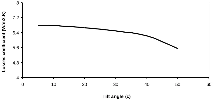
- Figurer 5 effect of the collector tilt angle was observed that it the losses coefficient is insignificantly affected by variation in tilt angle (5-50 degree C), the losses coefficient progressively drops (6.8-6.32 W/m2.K) with higher values of tilt angle.
- Figurer 6 correlation between the overall heat losses coeficient and the ambient temperature srounding solar collector, the result indicates that the losses coefficient increasing (7.32-7.8 W/m2.K) as the ambient temperature (10-60 C) also increases, from figurer observed that for a 10 C rise in the ambient temperature, the losses coefficient increases about 0.07, this trend that the collector losses will be minimum in morning.
Fig. 2: correlation between losses coefficient with Absorber plate temperature for solar collector.
0
2
4
6
8
10
12
0
10
20
30
40
50
60
70
80
Absorber plate temperature (C)
To
p
los
s
e
s
c
oe
ff
ic
ie
nt
(W
/m
2
.K
)
At ambient temperature 15 C
At ambient temperature 25 C
~ 85 ~
Fig 3: Relation between losses coefficient with wind velocity over solar collector.
Fig 4: Relation between losses coefficient with air gap spacing between the absorber plate and the glassing cover of solar collector.
Fig. 5: Relation between losses coefficient with Tilt angle of solar collector.
0 2 4 6 8 10 12
0 1 2 3 4 5 6
Wind velocity (m/s2)
Lo
s
s
e
s
c
oe
fi
c
ie
nt
(
W
/m
2
.K
)
0 2 4 6 8 10 12
0 0.02 0.04 0.06 0.08 0.1 0.12
Air gap (m)
Lo
s
s
e
s
c
oe
fi
c
ie
nt
(
W
/m
2
.K
)
4 4.8 5.6 6.4 7.2 8
0 10 20 30 40 50 60
Tilt angle (c)
Lo
s
s
e
s
c
oe
ff
ic
ie
nt
(
W
/m
2
.K
Fig. 6: Relation between losses coefficient with ambient temperature of solar collector.
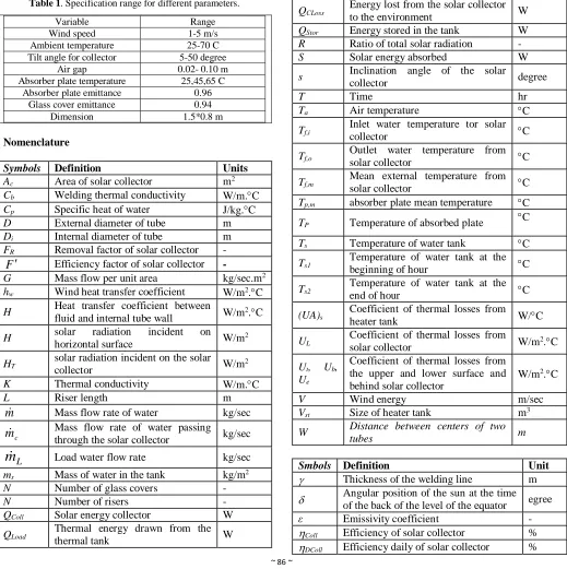
Table 1. Specification range for different parameters.
Variable Range
Wind speed 1-5 m/s Ambient temperature 25-70 C Tilt angle for collector 5-50 degree
Air gap 0.02- 0.10 m Absorber plate temperature 25,45,65 C
Absorber plate emittance 0.96 Glass cover emittance 0.94
Dimension 1.5*0.8 m
Nomenclature
Units Definition
Symbols
m2
Area of solar collector
Ac
W/m.C Welding thermal conductivity
Cb
J/kg.C Specific heat of water
Cp
m External diameter of tube
D
m Internal diameter of tube
Di
-Removal factor of solar collector
FR
-
Efficiency factor of solar collector
F
kg/sec.m2
Mass flow per unit area
G
W/m2.C
Wind heat transfer coefficient
hw
W/m2.C
Heat transfer coefficient between fluid and internal tube wall
H
W/m2
solar radiation incident on horizontal surface
H
W/m2
solar radiation incident on the solar collector
HT
W/m.C Thermal conductivity K m Riser length L kg/sec Mass flow rate of water
m
kg/sec Mass flow rate of water passing
through the solar collector
c
m
kg/sec Load water flow rate
L
m
kg/m2
Mass of water in the tank
ms
- Number of glass covers
N
-Number of risers
N
W Solar energy collector
QColl
W Thermal energy drawn from the thermal tank
QLoad
W Energy lost from the solar collector to the environment
QCLoss
W Energy stored in the tank
QStor
-Ratio of total solar radiation
R
W Solar energy absorbed
S
degree Inclination angle of the solar
collector s hr Time T C Air temperature Ta C Inlet water temperature tor solar collector
Tf,i
C Outlet water temperature from solar collector
Tf,o
C Mean external temperature from solar collector
Tf,m
C absorber plate mean temperature
Tp,m
C Temperature of absorbed plate
TP
C Temperature of water tank
Ts
C Temperature of water tank at the beginning of hour
Ts1
C Temperature of water tank at the end of hour
Ts2
W/C Coefficient of thermal losses from
heater tank
(UA)s
W/m2.C
Coefficient of thermal losses from solar collector
UL
W/m2.C
Coefficient of thermal losses from the upper and lower surface and behind solar collector
Ut, Ub,
Ue
m/sec Wind energy
V
m3
Size of heater tank
Vst
m Distance between centers of two tubes W Unit Definition Smbols m Thickness of the welding line
egree Angular position of the sun at the time of the back of the level of the equator
-Emissivity coefficient
ε
% Efficiency of solar collector
Coll
% Efficiency daily of solar collector
DColl 4 4.8 5.6 6.4 7.2 8
0 10 20 30 40 50 60 70
Ambient temperature (C)
~ 87 ~
Degree Fall angle of solar radiation
-Reflection coefficient
r
-Emission factor
Degree Angle of latitude
Degree Hour angle
4. Conclusion
-Theortical analysis was performed on a flat plate collector with a single glass cover.The values of loses coefficient predicted according to emperical correlation of Malhorta laid between (4.5-11.2 W/m2.K) for different paramerts. - The degree of the effect of these parameter on the collector performance as has been shows is a strong guide for designers and users for optimization of the system design and its operation of solar flate plate collector.
5. References
1. Wackelgard E, Niklasson GA, Granqvist CG. Selective solar absorbing coatings. In: Gordon J, editor. Solar energy: the state of the art. Germany: ISES; 2001. p. 109–44.
2. Francia G. A new collector of solar radiant energy. UN Conf New Sources Energy, Rome 1961; 4:572. 3. Garg H. P. and U. Rani 1980. Loss coefficients from
solar flat plate applied energy. 7: 109-117.
4. Hottel HC, Woertz BB. 1942. The performance of flat-plate solar heat collectors. Trans ASME. 64: 94-102. 5. Tabor. H, Radiation. 1985. Convection and conduction
coefficients in solar collectors, Bull. Res Council of Israel. 6C. pp. 155-176.
6. Klein SA. 1975. Calculation of flat-plate collector loss coefficients. Sol. Energy.17: 79-80.
7. Klein SA. In: Duffie JA, Beckman WA. 1991. Solar engineering of thermal processes. New York: Wiley. p. 260.
8. Fayad, M.A., Herreros, J.M., Martos, F.J. and Tsolakis, A., 2015. Role of alternative fuels on particulate matter (PM) characteristics and influence of the diesel oxidation catalyst. Environmental science & technology, 49(19), pp.11967-11973.
9. Mullick SC, Samdarshi SK. 1988. An improved technique for computing the top heat loss factor of flat-plate collector with a single glazing. ASME J Sol Energy Eng. 110: 262-7.
10. Malhotra A, Garg HP, Palit A. 1981. Heat loss calculation of flat-plate solar collectors. J Thermal Eng (J Indian Soc Mech Eng). 2(2): 59-62.
11. Pillai P. K. C and R. C. Agarwal, Ananalytical approach for optimizing a set of α and ε values for solar energy applications, Energy conv. and Mgmt. 20:205 to 212.
12. Bhatt M.K. Gaderia S.N. and Channiwala S.A. ( 2011). Experimental Investigations on Top Loss Coefficients of Solar Flat Plate Collector at Different Tilt Angle. Journal of World Academy of Science, Engineering and Technology, Vol. 79, Pp 432 – 436.
13. Fayad, M.A, Analytical solution for predicting heat pipe performance- AL-Taqani, 2012.
14. Kumar, S, Chourasia, B.K. and Mullick, S.C. (2005). Wind heat transfer coefficient in flat plate solar collectors, SESI journal, 15: 30.
15. Kalogirou S. Solar energy engineering: processes and systems. First edition, USA: Academic Press Elsevier Inc., 2009. 760 p
16. Fayad, M.A., Fernández-Rodríguez, D., Herreros, J.M., Lapuerta, M. and Tsolakis, A., 2018. Interactions between aftertreatment systems architecture and combustion of oxygenated fuels for improved low temperature catalysts activity. Fuel, 229, pp.189-197. 17. Malhortra A., Garg H.P. and Palit, A. (1981). Heat loss
calculation of flat-plate solar collectors, Journal of Thermal Energy, Vol. 2, and Pp. 2
18. Salman, A.Z., Fayad, M.A. and Salam, A.Q., Theoretical Investigation of Buoyancy-driven Cavity Flow by Using Finite Element.
19. Bogarra-Macias, M., Doustdar, O., Fayad, M.A., Wyszyński, M.L., TSOLAkiS, A., Ding, P., Pacek, A., MARTiN, P., Overend, R. and O'Leary, S., 2016. Performance of a drop-in biofuel emulsion on a single-cylinder research diesel engine. Combustion Engines, 55.