Review Article
SIMPLIFIED TOOTH MOVEMENT WITH MINI IMPLANTS AND
ORTHODONTIC ELASTICS
-
A PROSTHODONTIC APPROACH
Lukram A
1*, Khan M
2, Sahu K
2, Jadhav S
21
Prosthodontics And Maxillofacial Implantologist, Imphal, INDIA.
2
PG Resident, TMDC and RC, Moradabad, Uttar Pradesh, INDIA.
Article History Received: 15 July 2015 Revised: 22 July 2015 Accepted: 27 July 2015
*Correspondence to: Anooj Lukram,
Sega road top leriak machin, Imphal, INDIA.
ABSTRACT
Mini screw implants, as temporary anchorage devices, are accepted components of orthodontic treatment. Different methods exist in respect of the comparatively simple techniques of placement of these mini screws. While the technique is of primary relevance to the orthodontists, the use of mini screws as an aid for pre-prosthodontic tooth movement is also of relevance to the prosthodontists. Modifications of these techniques are always made by the individual prosthodontist to suit their plan of treatment in order to curtail interdependence. Examples of appliances used in conjunction with mini screws are described in this article.
KEYWORDS:Mini-screws, Orthodontic extrusion, Hydrocolloid impression.
INTRODUCTION
To reduce the occurrence of complication for a planned restorations, the position and the alignment of teeth must be assessed and corrected1. There are many definitive treatment modalities for tooth repositioning.
In selected cases where orthodontic repositioning is considered, we prosthodontist have to refer the cases to an orthodontist. The orthodontist will follow his own treatment modalities and protocol which may take months to a year2.
While using fixed orthodontic appliances, undesirable side effects can occur, even when using several tooth for anchorage3. This paper, will review various treatment modalities in which removable prosthodontic appliances used for tooth repositioning and promote correction of malocclusion which are cost effective and also gives us independence from interdependence.
ORTHODONTIC INTRUSION OF TEETH IS
ASSOCIATED WITH 3 MAIN CONCEPTS
1. First, in order to obtain anchorage the appliance should be rigid and include as many teeth as possible.
2. Second, the force application point must be through the center of resistance.
3. Third, the recommended amount of force to intrude a single rooted tooth is 10 g to 20 g (0.098 N to 0.196 N).
INTRUSION BY REMOVABLE
INTEROCCLUSAL DEVICE
Interdisciplinary therapy is used to treat a patient missing a single posterior tooth opposing an extruded tooth. The simple technique uses a removable inter-occlusal device and elastic band for orthodontic intrusion over a 2-month period.
irreversible hydrocolloid impression4. Fabricate a retainer for the arch in which intrusion is complete. Require full-time wear of the retainer during fabrication of the definitive prosthesis. Post-operative radiograph
shows molar extruded with opposite tooth with implant (Fig 5)4 and polished tooth surface after removing the retention buttons (Fig 6)4.
Figure 1: Radiographic Examination
Figure 2:Resin Retention Buttons Figure 3:Bummer 3/16”, 6 Oz. Intraoral Elastic
Figure 4: Evenly Distributed Occlusal Contacts
Figure 5: Post-Op Molar Extruded With Opposite Tooth With Implant
Figure 6: Polished Surface After Removing The Retention Buttons
INTRUSION
BY
TEMPORARY
ANCHORAGE DEVICE
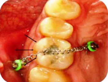
TECHNIQUE: For maxillary molar intrusion using two TADs, one miniscrew should be placed in the buccal region between the first and second molar5; the other in the palatal slope between the second premolar and first molar just medial to the greater palatine nerve (Fig 7)2. This will allow the elastic chain or nickel-titanium coil to pass diagonally across the occlusal table
(Fig 7)2. TAD supported molar intrusion is controlled and timely and may be accomplished without the need for full-arch brackets and wires6. Supraerupted maxillary first molars can be intruded 3 to 8 millimeters in 7.5 months (approximately 0.5-1.0 mm per month)7 (Fig 8)2, without loss of tooth vitality, adverse periodontal response or radio graphically evident root resorption2.
EXTRUSION
BY
INTRA-OCCLUSAL
DEVICE
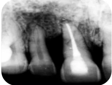
TECHNIQUE: An interocclusal appliance was fabricated to facilitate the orthodontic extrusion. Intraoral adjustment of the appliance was performed to allow function without occlusal interference8. Orthodontic hooks were bonded with composite resin at the buccal and lingual cervical regions of the right central and lateral incisors (Fig 9)2. Radiograph shows extruded central incisor (Fig 10)9. The incisal edges of the incisors were reduced by approximately 1 mm and elastic bands were connected to the hooks over the appliance for activation of tooth movement. The parameter used to determine slow orthodontic extrusion was 1 week of activation per millimeter, during which time period, an eruptive force was maintained on the
tooth, and 3 weeks for retention or stabilization, during which time the extruded tooth was maintained in the new position9.
EXTRUSION
BY
FIBER
REINFORCED
COMPOSITE RESIN
TECHNIQUE: The Goal of this technique is to increase the crown length (Fig 11)9. Here J hook is luted with resin cement on the remaining crown portion of the tooth which is need to be extruded (Fig 12)9.Fibre reinforced on the palatal aspect of 21,12 teeth at an appropriate position of 6mm distance from J hook in the maxillary right central incisor and finally j hook is activated (Fig 13)9. Post-Operative the patient was reviewed at weekly interval for 4 weeks. After 4 weeks 3mm eruption was evident clinically andradiographically.
Fig 9: Orthodontic Hooks Were Bonded With Composite Resin At The Buccal And Lingual Cervical
Regions
Fig 10. Radiograph Shows Extruded Central Incisor.
Fig 11: Pre Treatment Tooth For Extrusion.
Fig 12: J Hook Is Luted With Resin Cement
Figure 13: Fibre Reinforced On The Palatal Aspect Of 21,12 Teeth
DISTALIZATION VIA ACRYLIC WEDGE
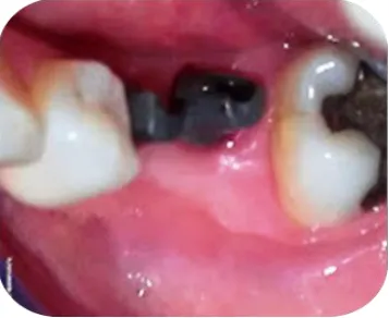
The goal is to fit a longer disto-mesial crown on the back implant that tilts the second molar back to a more upright angle (Fig 14)5.Acrylic wedge is kept in place as show in the (Fig 15)5. Width of acrylic wedge is increased in increments. Temporary crown is used to keeps the wedge in place (Fig 16)5. Patient should be instructed not to overload the implant by biting
Figure 16: Temporary Crown Is Used To Keeps The Wedge In
Place
Figure 17: Buccal View Of Temporary Crown
Figure 18: Final Restoration (Post-operative).
DISTALIZATION BY INTERIM SCREW
RETAINED CROWN AND SEPARATOR
ELASTIC
Common mistake during implant therapy include inadequate consideration of the available mesiodistal space and /or the presence of proximally inclined in teeth at the implant site. Here separator elastic is placed in contact point area between first and second molar with
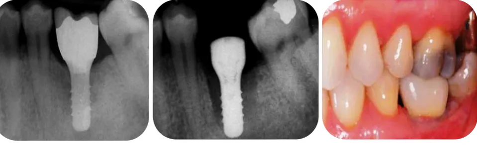
Implant supported screw-retained provisional crown (Fig 19)1.Figure shows open contact point of 1.5mm distally, at 2-week follow-up appointment (Fig 20)1. Implant-supported final restoration is shown in (Fig 21)1. Pretreatment dental implant showing mesial angulation of second molar (Fig 22)1. Post treatment dental implant showing final restoration (Fig 23)1.
Figure 19: Seperator Elastic In Place. Figure 20: Open Contact Point Of 1.5mm Distally At 2-Week Follow-Up
Figure 14: Implant That Tilts The IInd Molar Back To More Upright Angle
Figure 21: Implant-Supported Final Restoration
Figure 22: Mesial Angulation Of Second Molar
Figure 23: Post treatment dental implant showing final restoration
CONCLUSION
The techniques are conservative, minimizes the need for surgical intervention, and inexpensive. Lastly, the technique allows for simpler Prosthodontic treatment and no interdependence. Some of the pictures have been taken from references articles for illustration purposes.
REFERENCES
1. Yao cc, et al, angle orthod. 2004; Vol. 74:550 2. Neal D Kravitz, DMD, Budi Kusnoto, DDS, MS; T. Peter Tsay, DDS, PhD; William F. Hohlt, DDS The use of temporary anchorage devices for molar intrusion, JADA 2007;138(1):56-64.
3. Thomas PM. Temporary anchorage devices: indications and Applications, J. Oral maxillofac. Surg. 2007; 65:9 supplement, 78.
4. Rotella M, Geminiani A, Ercoli C. Simplified orthodontic tooth movement with dental implants and orthodontic elastics: a clinical report. J Prosthet Dent,2011; 105:363-6.
5. Telma Martins de Araújo, Mauro Henrique Andrade Nascimento,Fernanda Catharino Menezes Franco, Marcos Alan Vieira Bittencourt, Tooth intrusion using mini-implants, Dental Press J. Orthod. 2008; 13(5), 36-48.
6. Roberto Carrillo AP. Emile Rossouw,b Pedro F Franco,c Lynne A. Opperman,d and Peter H. Buschange, Intrusion of multiradicular teeth and related root resorption with mini- screw implant anchorage : A
radiographic evaluation, Am J Orthod Dentofacial Orthop 2007;132:647-55.
7. Yanosky MR., Holmes JD. Mini-implant temporary anchorage Devices: orthodontic applications; compend. Cont. Educ. Dent, 2008; 29:12.
8Sudhin. dra Mahoorkar, Shivakumar.N. Puranik, Arvind Moldi, Ramesh Chowdhary, Baswakumar Majge, Management of Supra-erupted Posterior Teeth- A Review, International Journal Of Dental Clinics 2010: 2(3)27-30
9. Kim SH, Tramontina VA, Papalexiou V, Luczyszyn SM. Orthodontic extrusion and implant site development using an interocclusal appliance for a severe mucogingival deformity: a clinical report. J Prosthet Dent 2011;105:72-7.
Copyright: © the author(s) and publisher IJMRP. This is an open access article distributed under the terms of the Creative Commons Attribution Non-commercial License, which permits unrestricted non-commercial use, distribution, and reproduction in any medium, provided the original work is properly cited.