Voice Based Smart Wheelchair for Disabled
using Android
M.N.Srinithya Visahan.S
Assistant Professor UG Scholar
Department of Electronics and Communication Engineering Department of Electronics and Communication Engineering CCET, Oddanchatra, Dindigul, Tamilnadu CCET, Oddanchatra, Dindigul, Tamilnadu
Joshuva.J Bijo Joseph
UG Scholar UG Scholar
Department of Electronics and Communication Engineering Department of Electronics and Communication Engineering CCET, Oddanchatra, Dindigul, Tamilnadu CCET, Oddanchatra, Dindigul, Tamilnadu
Chandra Mohan.K UG Scholar
Department of Electronics and Communication Engineering CCET, Oddanchatra, Dindigul, Tamilnadu
Abstract
This paper is to describe an intelligent motorized wheel chair for handicapped person using voice technology. Our goal is to move towards making accessible he manipulation of everyday objects to individuals with motor impairments. It can be controlled through simple voice commands using voice controller. A voice recognition application which is interfaced with motors through microcontroller. We are using Hidden Markov Model algorithm (HMM). A novel approach is proposed in this paper to impart intelligence to a low cost smart wheelchair based on Embedded C system.
Keywords: Embedded C; Hidden Markov Model Algorithm; Voice Recognition(VR); Microcontroller
________________________________________________________________________________________________________
I. INTRODUCTION
The aim of this research is the development of intelligent solutions for controlling electrical wheelchairs without using a joystick. This type of user has increased rapidly in the recent years due to the increasing of accidents, wars, physically handicapped and an aging population. We use Android phone for sharing voice recognition through Bluetooth and operate the wheelchair with the help of the microcontroller. This is a dual input type operated wheel chair that is made to work based on voice and button module commands.
In particular, robotic wheelchairs may help in maneuvering a wheelchair and planning motion. Recently, research of assistant robots is also emerging field of robotic applications.
II. VOICE RECOGNITION ALGORITHM
There are many speech and voice recognition algorithms used in voice recognition software and hardware systems and techniques.
Hidden Markov Model (HHM)
HMM is a statically discrete-time stochastic process model, it is a kind of signal processing technique that has been used successfully in speech and handwriting character recognition. HMM is characterized by three matrices namely S, O, π.
S: State transition probability matrix (I*I)
O: Observation symbol probability distribution matrix (I*J) π: Initial state distribution matrix (I*1) Where,
I: Number of states in the HMM model
J: Number of distinct observation symbols per state
The symbol λ = {S, O, π} represent all the parameter set of the model. If suppose L is the word to be recognized by the model, each word will be modeled by a distinct HMM. Each word has K utterances in the training set, the following steps need to be performed to obtain the isolated word recognition:
1) A HMM model λ w must be established for each word W, the parameters (S, O, π) for the wth word must estimate the optimal likelihood of the training set observations.
The observation sequence measurement M = (m1, m2… mT) by the feature analysis of the voice corresponding to the word. Model likelihood calculations for all possible models (using Forward Backward algorithm), P (M/λ w), 1≤w≤W.
Selection of the word that have the highest model likelihood as:
W= arg max W P M λ ----1 Where arg max is the argument of the maximum.
III. RELATED WORK
Hand Gesture Movement Based Wheelchair. Uses Accelerometer and Hand Gloves for wheelchair control. Voice Control Wheelchair (Base Paper concept) HM 2007 IC is used for the voice recognition purpose. Not so accurate in recognition. Joystick wheelchair and head control wheelchair. Not so accurate due to components used and environmental disturbances. The voice recognition IC HM2007 is capable of operating in speaker independent speech recognition mode. In speech recognition mode, first, the voice is recorded to the external SRAM attached to the IC with the help of a directly connected microphone at the analog input terminal of HM2007 keeping the mode selection key in the record mode. In this way 40 0.9second long words or 20 1.92-second long words or phrases can be recorded into the memory. After training the voice recognition IC like above the mode selection key is switched to voice input mode. Here at a particular instant the speech through the microphone is compared with the recorded sound and according to that digital output is generated. The output of voice recognition IC is then fed to the digital input ports of the ATMEGA 8 microcontroller. The microcontroller on receiving the Signal directs the motors through the control circuit. The control of speed and direction are done in this way. The change of direction is achieved by changing the direction of current flow through the motor and speed control is achieved by varying the current through the motor. The Communication of HM2007 with microcontroller follows the protocol given below:
1) Microcontroller indicates on the S-bus that it is ready to receive the HM2007's status.
2) HM2007 indicates its status on the K-bus. Z Microcontroller switches its pins connected to the HM2007's K-bus to inputs and reads status from the K-bus.
3) Microcontroller switches its pins connected to the HM2007's K-bus to outputs and writes a command to the Kbus. 4) Microcontroller indicates on the S-bus that the HM2007 should read the K-bus for a command.
5) HM2007 reads the K-bus for the command.
6) HM2007 responds to the command and places the results on the K-bus. 7) Microcontroller reads the K-bus to determine the result of the command. 8) Microcontroller reads the K-bus to determine the result of the command.
IV. METHODOLOGY
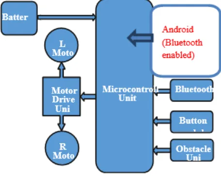
The aim of the proposed system is to use of different available body parameter as a control input to the microcontroller
Fig. 1: Block diagram
Peripheral Interface Controllers (PIC)
CPU and is integrated with various types of memory modules (RAM, ROM, EEPROM, etc), I/O ports, timers/counters, communication ports, etc.
All PIC microcontroller family uses Harvard architecture. This architecture has the program and data accessed from separate memories so the device has a program memory bus and a data memory bus (more than 8 lines in a normal bus). This improves the bandwidth (data throughput) over traditional von Neumann architecture where program and data are fetched from the same memory (accesses over the same bus). Separating program and data memory further allows instructions to be sized differently than the 8-bit wide data word.
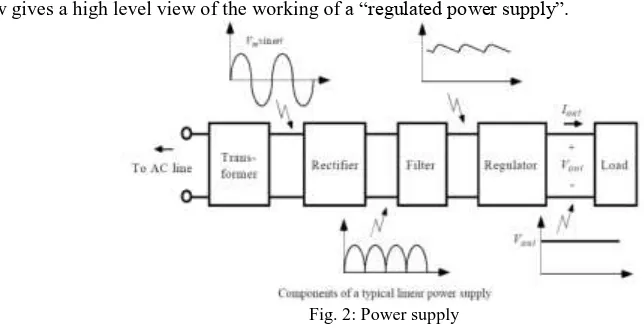
Power Supply
The circuit below gives a high level view of the working of a “regulated power supply”.
Fig. 2: Power supply
Now comes the rectifier part. This converts the AC voltage output of the transformer to a DC voltage. It just reverses the polarity of one half of the period of the AC signal. This will make both parts have the same polarity. Here we use a full wave bridge rectifier to convert the AC signal to DC
Vin/Vout=Nin/Nout Vin = Input AC voltage
Vout = Output AC voltage
Nin = Number of turns at the input terminal of transformer Nout = Number of turns at the output terminal of transformer
Bluetooth Module
Fig. 3: Bluetooth
Note 1:
This is a single unit only. We recommend the purchase a USB dongle to interface to a computer if you do not already have access to a computer with Bluetooth connectivity.
Note 2:
Do not attach this device directly to a PC RS232 Port. You will need an RS232 to TTL converter circuit if you need to attach this to a computer.
Note 3:
I/O Pins are not 5V Tolerant, use level converter for interfacing with 5V Microcontrollers
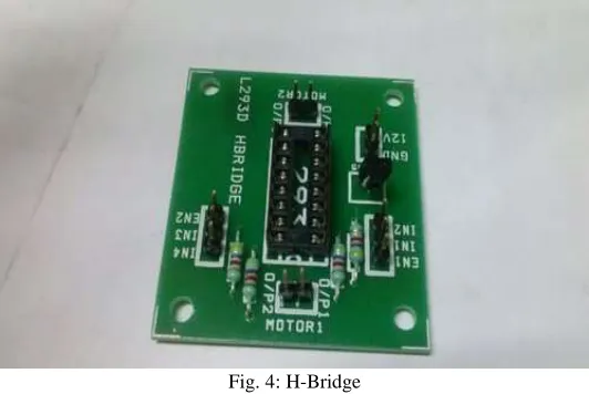
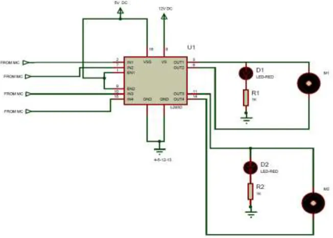
H-Bridge L293d Using Motor Driving Circuit
Fig. 4: H-Bridge
Fig. 5: H-bridge circuit Board Special Features
Four motor direction indicator LEDS. Schottky EMF-protection diodes.
Socket pin connectors for easy logic interfacing. Enable pins are user accessible.
IR Sensor
This infrared transmitter and receiver is called as IR TX-RX pair. Color of IR transmitter and receiver is different. However, you may come across pairs which appear exactly same or even has opposite colors and it is not possible to distinguish between TX and RX visually. In case you will have to take help of multi meter to distinguish between them. Pair of Infrared LED and Photo diode tuned to same IR wave length. You can use this sensor for your Robotics, Pulse oximeter and other applications. This sensor can be used to detect reflecting silver/white strip, obstacle detection, flame detection, etc.
IR Sensor Circuit Using Lm358
Infrared transmitter is one type of LED which emits infrared rays generally called as IR Transmitter. Similarly, IR Receiverisused to receive the IR rays transmitted by the IR transmitter.
Fig. 6: IR sensor circuit
interrupt the IR rays between the IR transmitter and receiver, the IR receiver is not conducting. So the comparator non inverting input terminal voltage is higher than inverting input. Now the comparator output is in the range of +5V. This voltage is given to microcontroller or PC and led so led will glow.
Motors
The system includes two DC motors with steel gearboxes. The motor is fixed in the Jaguar lite robot system chassis, the rating operation voltage for the motors is 24 V and the rated current is 7.5 A. The maximum weight which can be held by this type of DC motor is not sufficient for wheelchair real time application and it will be replaced in the future work.
V. WORKING DESCRIPTION
When the voice is detected, the wheelchair can be controlled to move in that direction by giving commands to the wheelchair. These commands are transferred to the wheelchair using electrical signals which are used the drive the left or right motor of the wheelchair. There are basically two motors connected to the left and right wheels of the wheelchair. The electrical signals are transferred to these motors using some hardware ports, called the communication ports. Generally, the communication port is the parallel port. There are some basic predefined pins of this parallel port which accept the commands given to the wheelchair in the form of electrical signals. For the purpose of demonstration of wheelchair movement using eye motion, a wheelchair model is designed in this project, which works on batteries.
Four wheels are used in the wheelchair for proper balancing. The movement of wheels is controlled by DC motors which are attached to the wheelchair. Two wheels located on left side of the wheelchair are controlled by one motor and similarly the wheels on the right side are controlled by the second motor. The other circuitry built into the wheelchair includes the transmitter and receiver circuits and the obstacle detection circuit. It involves two IR signal emitters which emit IR signals continuously when some obstacle appears in front of the wheelchair, these IR signals are obstructed, and reflected back. These reflected signals are then detected by the IR sensor.
Table – 1 Command control action
Command Definition
Forward Both motors rotate forward Left Right motor rotates forward and the left stop Right Left motor rotates forward and the right stop Backward Both motors rotate backward
Stop Both motors stop
Speed one Increase the speed or decrease from speed two Speed two Increase the speed
VI. CONCLUSION
We have presented a novel technique to help the handicapped peoples. We are using both voice and button module. In case of any malware process we can switch the module.
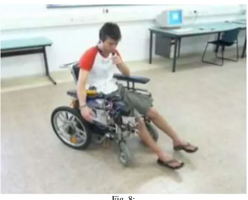
VII. RESULTS
Fig. 8:
REFERENCES
[1] Design and testing of low cost three-modes of operation voice controllerfor wheelchairs and rehabilitation roboticsRuzaij, M.F.; Neubert, S.; Stoll, N.; Thurow, K.Intelligent Signal Processing (WISP), 2015 IEEE 9th International Symposium onYear: 2015
[2] International Journal of Engineering Trends and Technology (IJETT) – Volume 20 Number 2 – Feb 2015 ISSN: 2231-5381 http://www.ijettjournal.org Page 48 Wireless Speed and Direction Control of Dc Motor by Using Radio Frequency Technology
[3] R.A.Ramlee, M.H.Leong, R.S.S.Singh, M.M.Ismail, M.A.Othman, H.A.Sulaiman, M.H.Misran, M.A.Meor Said, “ Bluetooth Remote Home Automation System Using Android Application”, The International Journal of Engineering And Science (IJES) Volume- 2 ,Issue 01 ,Pages- 149-153 ,2013 ISSN: 2319 – 1813 ISBN: 2319 – 180
[4] Aruna. C, DhivyaParameswari. A, Malini. M and Gopu. G, “Voice Recognition and Touch Screen Control Based Wheelchair for Paraplegic Persons”, in Proc. Green Computing, Communication and Electrical Engineering, Coimbatore, 2014, pp. 1-5.
[5] Akira Murai, MasaharuMizuguchi, Takeshi Saitoh, Member, IEEE, TomoyukiOsakiand, RyosukeKonishi, “Elevator Available Voice Activated Wheelchair”, in Proc. 18th IEEE International Symposium on Robot and Human Interactive Communication, Toyama, Japan, Sept. 27-Oct. 2, 2009, pp. 730-735. [6] Masato Nishimori, Takeshi Saitoh and RyosukeKonishi, “Voice Controlled Intelligent Wheelchair”, in Proc. SICE Annual Conference 2007, Sept. 17-20,
2007, Kagawa University, Japan, pp. 336-340.
[7] XiaolingLv, Minglu Zhang and Hui Li, “Robot Control Based on Voice Command”, in Proc. IEEE International Conference on Automation and Logistics, Qingdao, September 2008, pp. 2490-2494.
[8] Muhammad Tahir Qadri and Syed Ashfaque Ahmed, “Voice Controlled Wheelchair Using DSK TMS320C6711”, in Proc. 2009 International Conference on Signal Acquisition and Processing, Kuala Lumpur, 2009, pp. 217 -221.
[9] Lawrence Rabiner, Biing-Hwang Juang, “Fundamentals of speech recognition”, Pearson Education, 2003.
[10] Vibha Tiwari, “MFCC and its applications in speaker recognition”, International journal on emerging technologies, 2010, pp. 19-22.