Approach for the Visualization of Geometric Uncertainty
of Assemblies in CAD-Systems
Felix Heimrich
*, Reiner Anderl
Department of Computer Integrated Design (DiK), Technische Universität Darmstadt, Otto-Berndt-Straße 2, 64287 Darmstadt, Germany.
* Corresponding author. Tel.: +49 (0) 6151-16-5145; email: [email protected] Manuscript submitted August 11, 2015; accepted October 21, 2015.
doi: 10.17706/jcp.11.3.247-257
Abstract: The foundation for the development of successful products is based on knowledge about the characteristics of the product throughout the entire product life cycle. However, uncertainties can arise over the life cycle. These characteristics simultaneously influence each other and therefore the characteristics of the product in the product development and usage phases need to be identified. This uncertainty can have negative economic consequences, such as functional failures or oversizing. In this paper a concept for the visualization of geometric uncertainty of assemblies in CAD-Systems based on ontologies will be presented. This is an approach for visualizing various types of uncertainty of different product life cycle phases to control uncertainty in load-carrying systems during virtual product development. The concept is a part of the research activities of the CRC 805 (Collaborative Research Center 805).
Key words: Uncertainty, visualization, information model.
1.
Introduction
A prerequisite for success in today’s global markets is the efficient development of complex products. This prerequisite is met through the support of the development process through the use of computer-based methods in the product creation phase. At the same time, the archiving of process data is gaining ever more importance under industry 4.0. Under this pretense, the focus is using the part as an information carrier, where the information contained within the part is necessary across different product life cycles [1], [2]. Special interest must be dedicated to the uncertainty of product and process properties from the product creation and usage phases. The communication of information about uncertainty in product development provides an extensive overview of potential product and process characteristics over the entire product life cycle and thus can be significantly influenced during the product development. This information is collected through various methods such as e.g. quality checking methods, usage monitoring or process capability analysis. They are related to each other within different life cycle phases [3]. Today, this information from the product creation and use phases is quite often inadequately described. The decisive factor here is not only the collection, harmonization and feeding back relevant data into a designated information model, but also the preparation and provision of the information about uncertainty for engineers in product development.
(Computer Aided Design).
A new concept has been developed in which the virtual product development process is supported, with respect to geometric uncertainty in load-bearing systems using an assembly-oriented visualization technique and an associative information model.
2.
State of the Art
In this chapter the basic approach of managing uncertainty, the process model, its representation into an information model and previously developed approaches for visualization of uncertainty are introduced. Furthermore an example showing the weaknesses of existing concepts will be presented.
2.1.
Product Life Cycle (PLC)
The PLC can be described from two view points. Where the economic point of view aims at analyzing key success factors such as turnover, sales and costs, the focus of the information technology view lies on structuring product life cycle into phases such as development, production, usage, recycling and tracking the product while passing through these phases [4]. In Fig. 1 a third approach is shown as developed for the development of environmentally sound products. In the framework of the CRC 805 the sections product development, production, and usage are of special interest. The product development has thereby an influence on all phases of the product lifecycle.
Definition of processes
Anticipate processes
Final Design
Product
Material Production Usage Recycling
Draft Conception
Planning Idea
P
roduct
D
e
ve
lopm
e
n
t
Fig. 1. Relationship between processes in the CRC 805 for controlling uncertainty of the phases in the product life cycle [4].
Product development is a complex process in which uncertainty over the future process characteristics of the product is an issue continuously. During the creation process there are many decisions that need to be drawn which influence the products´ successful appearance in successive lifecycle phases. However, no clear prediction can be made about any consequences of the impact of uncertainty with respect to decisions taken. In addition, there are a lot of locally separated participants which are involved in modern distributed product development. With increasing complexity of the product even more disciplines are involved and need to be integrated. This leads to an increase of the organizational effort to provide information to all those involved in decision making. To counteract negative impact of uncertainty in product development classically is based on methods to consider safety factors, which typically are based on experience. Thus a standard buffer is generated between the maximal acceptable deviation and the target value [3].
parts and its respective production process chain. Typically single values are in focus and they are not analyzed holistically [7].
Key approaches to analyze product properties in the usage phase are usage monitoring and failure analysis. With modern sensors, data are collected during the usage process and are evaluated directly [8], [9]. In such cases so-called embedded sensor-actor systems are applied [10].
In summary, the difficulty comprises the provision of prediction of product behavior and product impacting process properties in early phases of the product development for successive product life cycle phases. Hence a variety of methods have been used to meet these challenges [11], [12] an appropriate approach for predicting the impact of uncertainty is still missing.
2.2.
Uncertainty
The topic of uncertainty has been addressed in a number of scientific publications. A scientific outcome for reducing uncertainty is to increase knowledge and to continuously monitor product and process properties. In this engineering field of interest, two cases of uncertainty are distinguished based on [13]. The first case is called aleatoric uncertainty, which is defined by stochastically describable uncertainty. Through measuring uncertainty and through monitoring additional information about the product and process properties, a reduction of aleatoric uncertainty is feasible. The second case is called epistemic uncertainty, which results from a lack of knowledge. Epistemic uncertainty can be managed through the provision of appropriate knowledge.
The following concept contains the model of uncertainty which is developed in CRC 805. It provides three categories of uncertainty and is shown in Fig. 2 [14]. Here the aleatoric uncertainty is shown on the left side, where the complete and trustworthy information about the apparent uncertainty is available. The epistemic uncertainty, on the other hand, is located in the right side where the complete ignorance about the apparent uncertainty prevails. Between these two extreme cases of uncertainty the incertitude is located. Incertitude is characterized through a partially quantified probability. Ignorance means unknown uncertainty where uncertain properties and its relevance for the respective process are ignored. Incertitude is an estimated uncertainty where the cause and effect is well known, but not quantifiable with stochastic data. The stochastic uncertainty is characterized by the lowest uncertainty. Information about appropriate process properties is available and stochastically quantified e.g. as a distribution function.
Uncertainty
Effect
Probability
Uncertitude Ignorance
Stochastic Uncertainty
known unknown
acceptably quantified
partially quantified
Increasing amount of available, trusted information
Fig. 2. Uncertainty model, with based on [14].
2.3.
Ontology-Based Information Model
The information model developed at CRC805 is part of the concept COPE - (Collaborative Ontology-based Property Engineering-System), in which new methods and technologies for the depiction of uncertainty afflicted process properties are developed. Initially the uncertainty afflicted process properties were characterized and possibilities for their description are supported through a collaborative approach. The information model enables uncertainty afflicted process properties to be represented in a specific application context. A prototype software system integrated this ontology based information model into the 3D-CAD environment and supported to work interactively with the uncertainty information model which is also integrated into a product model. A detailed description of the ontology based information model can be found in [15].
2.4.
Visualization Methods
Uncertainty and its visualization has been the focus of scientific research for several years. The different disciplines can thereby select from a variety of visualization techniques in order to provide the user with the most user-friendly visualization of their specific uncertainty information. In [16] a comprehensive overview is provided and the most significant references from different disciplines that deal with the visualization of uncertainty are listed. A number of contributions have been identified in the area of geography and fluid flow analysis. In most cases vector fields are used [17], but displacement glyphs are also commonly applied [18]. Coloring or error bars are also be used for the visualization of geometric or positional differences. The main advantage is that visualization can be utilized in both 2D and 3D [19].
The approach with volume-rendered regions, according to [18], [20], has already been used for scanned freeform surfaces and the demonstration of their possible deviations. This visualization technique has been applied also in the CRC 805 for displaying geometric uncertainty in CAD systems, customized and linked to the corresponding information model [21].
2.4.1.
PMI – product manufacturing information
Product Manufacturing Information, short PMI, comprises non-geometric information and aims at providing annotations for 3D geometric models. PMI are required e.g. for the production of the single parts and assemblies. They can also reference to any data that is linked to geometry or topology of a 3D CAD-model. In feature-based CAD systems e.g. PMI are linked with manufacturing operations (NC programming) in order to visualize fits directly in the CAD system for the user and then finally for machining of part.
2.4.2.
Uncertainty data type – UDT
In mechanical engineering, a model called “uncertainty data type” (UDT), for the digital representation of uncertain product and process properties, is introduced in [22]. They form the basis for the description and presentation of uncertainty afflicted product properties. The approach aims at uncertain information representation including distributions, histograms, tolerances, intervals and single values. In [23] and [24] the uncertainty data types are extended to include classes of realization and, Fuzzy and 2d/3D intervals.
2.4.3.
Uncertainty-browser
The Uncertainty Browser, which is described in detail in [25], shows uncertainty afflicted product properties in form of a graphical user interface directly integrated in the CAD-System. The browser is designed as an integration area between the ontology editor and the CAD-system. The browser visually divides uncertainty information into categories based on a viewpoint concept. Individual uncertainties of a product can then be presented with Product Manufacturing Information (PMI), which is directly linked to the 3D model.
manufacturing and product usage phases are integrated by using an Extensible Markup Language (XML)-based interface.
2.4.4.
uCloud – uncertainty cloud
The concept of the uncertainty cloud aims at the visualization of geometric uncertainty of individual parts and is a part of the 3-Layer Approach described by [24]. The uCloud uses the graphical, symbolic, structural and verbal visualization to provide information. The result is a visualization through transparently shaded offset bodies, which are linked to the corresponding Uncertainty Data Types. Additionally, uncertainty information belonging to product structures such as lists, tables or tree structures are displayed. Fig. 3 illustrates the uCloud concept based upon an example of production-related deterministic geometrical deviations of an individual part. A detailed description can be found in [24].
Fig. 3. uCloud concept with deterministic geometrical deviations [24].
2.4.5.
Conclusion
Through closer inspection of the preceding approaches, it is found that visualization concepts developed are strictly limited to static visualization techniques, and that dynamic techniques have not yet been in focus. The disadvantage of static techniques is for the still possible mis-interpretation on the part, in particular in the case of enlarged geometrical uncertainty. It is also crucial, that uncertainty is considered only in the context of individual parts. The iimpact of uncertainty affected component properties reveal themselves only in the context of assemblies, in which a number of uncertainties are interdependent and influence each other. Classical tolerance stacking of geometric manufacturing tolerances is a typical example. Therefore, an approach for the visualization of geometric uncertainty in assemblies is required.
3.
Concept
The new approach for the visualization of geometric uncertainty is based upon the concept of Product Manufacturing Information (PMI). In order to make uncertainty information about afflicted part properties available throughout the entire assembly this information is attached to elements of the topology of the 3D CAD-models as attributes described as PMI. Afterwards the information is referenced to neighboring parts using bi-directional assembly constraints,. Geometric modifications such as shifts resulting from stacking of geometric uncertainty in the entire assembly are then enabled to be visualized in relation to any parts configurations.
3.1.
Object Attributes as Information Carrier
is referenced to topology entities of the 3D CAD-model and specified for object oriented implementation. For 3D CAD-models target topological entities for referencing PMI comprise:
Body
Shell
Face
Loop
Edge
Vertex
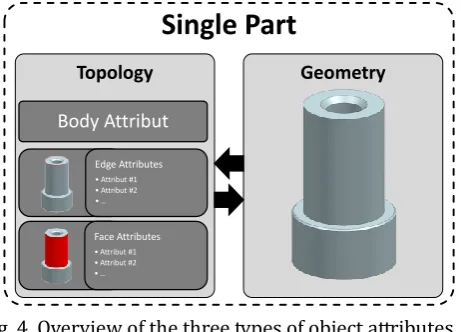
The focus of this approach aims at referencin topological entities Body, Face and Edge, as they are important for the assembly constraints. These entities will be further referred to as Body-, Face- and Edge-Attributes. The concept calls for an individual part specific information carrier which manages the subordinated object attributes, the Body-Attribute. This carrier contains all information from Face- und Edge-Attributes which belong to an entire body. This conceptual approach guarantees all object attributes can be associated also to neighboring parts. Through the configuration of individual parts via assembly constraints, the Body-Attributes associate corresponding parts with one another and enable bi-directional PMI exchange. One individual part contains exactly one Body-Attribute. On the contrary an individual part can contain Face- and Edge-Attributes which comprise uncertainty information mapped into a specific PMI associated with the afflicted object Property. Fig. 4 explains the concept of geometry and topology attributes of a single part.
Topology
Body Attribut
Edge Attributes • Attribut #1 • Attribut #2 • …
Face Attributes • Attribut #1 • Attribut #2 • …
Geometry
Single Part
Fig. 4. Overview of the three types of object attributes.
The attributes need to be be defined during the virtual product development process. Ideally all of the surfaces of the single part contain a Face-Attribute and all edges contain an Edge-Attribute in order to describe the underlying object properties.
The ontology based information model then provides the informational context which is then linked to the different attributes. They e.g. refer to the defined uncertainty types as introduced in chapter 2.4.
3.2.
Content of Information
Object attributes for bodies collect the information from attributes attached to the surfaces and edges of the part in order to provide a complete attribute bundle for the neighboring parts.
3.3.
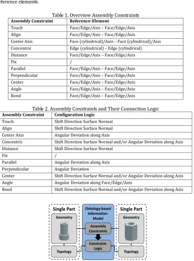
Constraint-Based Assembly Structure for Sharing Information between Single
Parts
The configuration of the individual parts is executed during virtual product development taking into account the assembly constraints. In order to reference individual parts within an assembly, the designer is provided with constraints which are listed in Table 1 below. In this case the assembly constraints can refer to different reference elements.
Table 1. Overview Assembly Constraints
Assembly Constraint Reference-Element
Touch Face/Edge/Axis – Face/Edge/Axis
Align Face/Edge/Axis – Face/Edge/Axis
Center Axis Face (cylindrical)/Axis – Face (cylindrical)/Axis
Concentric Edge (cylindrical) – Edge (cylindrical)
Distance Face/Edge/Axis – Face/Edge/Axis
Fix /
Parallel Face/Edge/Axis – Face/Edge/Axis
Perpendicular Face/Edge/Axis – Face/Edge/Axis
Center Face/Edge/Axis – Face/Edge/Axis
Angle Face/Edge/Axis – Face/Edge/Axis
Bond Face/Edge/Axis – Face/Edge/Axis
Table 2. Assembly Constraints and Their Connection Logic
Assembly Constraint Configuration Logic
Touch Shift Direction Surface Normal
Align Shift Direction Surface Normal
Center Axis Angular Deviation along Axis
Concentric Shift Direction Surface Normal and/or Angular Deviation along Axis
Distance Shift Direction Surface Normal
Fix /
Parallel Angular Deviation along Axis
Perpendicular Angular Deviation
Center Shift Direction Surface Normal and/or Angular Deviation along Axis
Angle Angular Deviation along Face/Edge/Axis
Bond Shift Direction Surface Normal and/or Angular Deviation along Axis
Geometry Geometry
Ontology-based
Information-Model
Assembly Constraints
Constraint-Logic Topology
Single Part
Topology
Single Part
Fig. 5. Connection of single parts with assembly constraints.
therefore also the die Edge- and Face-Attributes, of the individual parts are automatically linked bi-directionally with one another. Hence PMI containing geometric uncertainty can be referenced to the neighboring part. A configuration logic is defined for the provided assembly constraints, which defines how the geometric uncertainty is being propagated into the neighboring parts. Table 2 shows the assembly constraints with the corresponding configuration logic.
Supported through the configuration logic the outgoing geometric deviation of a single part is communicated to any other part found within the assembly and possible effects are calculated. Fig. 5 demonstrates the interlinking between attributes, individual parts, assembly constrains and configuration logic.
4.
Validation
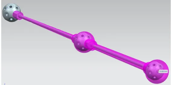
For the validation of the described concept the demonstrator of the CRC 805 is used, the modular active spring damper system. As a representative example a sub-assembly of the truss was selected. Fig 6 shows a part of the sub-assembly of the truss with the possible geometric deviation resulting from cumulative manufacturing tolerances of the individual parts in the context of assembly constraints and the applied constraint logic.
Fig. 6. Visualization of the possible geometric deviation of individual parts in assemblies.
The possible geometric deviation is visualized as faceted bodies. They allow of the analysis of the maximum deviation based on a stochastic distribution of manufacturing tolerances.
5.
Outlook
In the next step towards the visualization of uncertainty in assemblies a concept is needed for the processing of assembly constraints which influence each other. More precisely, a test of the constraints between individual parts has to be conducted as geometric modifications of the parts could lead to over-constrained systems which could then lead to the development of residual stresses. This is of special interest for the planning of the assembly sequences. Furthermore, non-geometric uncertainties, such as material properties, can be integrated despite the fact that their influence would first be of importance in life cycle phases production and usage.
6.
Conclusion
the a key success factor for safety. A representative application of this concept is virtual product development due to an abundance of information about product production as well as product usage phase.
Acknowledgment
We would like to thank the German Research foundation for funding this project within the Collaborative Research Center (CRC) 805. The development of a concept for visualization uncertainty in the product development process is part of the subproject A5 "Data Model for the Representation and Visualization of Uncertainty" of the Collaborative Research Center 805 "Control of Uncertainty in Load-Carrying Structures in Mechanical Engineering". For further information visit: http://www.sfb805.tu-darmstadt.de.
References
[1] Abele, E., Anderl, R., Metternich, J., Wank, A., Anokhin, O., Arndt, A., Meuth, T., & Sauer, M. (2015). Effiziente Fabrik 4.0 — Einzug von Industrie 4.0 in bestehende Produktionssysteme. Zeitschrift für Wirtschaftlichen Fabrikbetrieb, Jahrg., 110(3), 150–153.
[2] Anderl, R., Strang, D., Picard, A., & Christ, A. (2014). Integriertes Bauteildatenmodell für Industrie 4.0 — Informationsträger für cyber-physische Produktionssysteme. Zeitschrift für Wirtschaftlichen Fabrikbetrieb, Jahrg., 109(1-2), 64–69.
[3] Hanselka, H. (2008). Beherrschung von Unsicherheit in lasttragenden Systemen des Maschinenbaus — Einrichtungsantrag des SFB 805. Technische Universität Darmstadt.
[4] Abele, E., Anderl, R., & Birkhofer, H. (2005). Environmentally-Friendly Product Development — Methods and Tools. London: Springer Verlag.
[5] Anderl, R., Mecke, K., Sprenger, A., & Weitzmann, O. (2010). Ontology-based system for supporting the control of uncertainty in the product lifecycle. Proceedings of TMCE 2010. Ancona, Italy.
[6] Arndt, A., & Anderl, R. (2014). Generative Fertigung — Handlungsbedarfe und entscheidungsgestützte Prüfung auf RPT-gerechte Konstruktion. Entwerfen, Entwickeln, Erleben 2014: Beiträge zur virtuellen Produktentwicklung und Konstruktionstechnik, 667–679. Dresden.
[7] Syska, A. (2006). Produktionsmanagement — Das A-Z wichtiger Methoden und Konzepte für die Produktion von heute. Betriebswirtschaftlicher Verlag Dr. Th. Gabler. Wiesbaden.
[8] Vichare, N., Rodgers, P., Eveloy, V., & Pecht, M. (2007). Environment and usage monitoring of electronic products for health assessment and product design. Quality Technology & Quantitative Management, 4(2), 235–250.
[9] Hackmann, G., Guo, W., Yan, G., Sun, Z., Lu, C., & Dyke, S. (2014). Cyber-Physical Codesign of Distributed Structural Health Monitoring with Wireless Sensor Networks. IEEE Transactions on Parallel and Distributed Systems, 25(1), 63–72.
[10] Bertsche, B. (2008). Reliability in Automotive and Mechanical Engineering — Determination of Component and System Reliability. Berlin: Springer Verlag.
[11] Lindemann, U. (2009). Methodische Entwicklung technischer Produkte — Methoden flexibel und situationsgerecht anwenden. VDI-Buch. 3., Korrigierte Aufl. Berlin: Springer Verlag.
[12] Pahl, G., Beitz, W., Feldhusen, J., & Grote, K.-H. (2006). Konstruktionslehre — Grundlagen erfolgreicher Produktentwicklung. Methoden und Anwendung. 7., neu bearb. u. erw. Aufl. Berlin: Springer Verlag. [13] Lindley, D. V. (2006). Understanding uncertainty. Hoboken, N.J.: Wiley-Interscience.
[15] Sprenger, A. (2013). Kollaboratives, ontologiebasiertes system zur integration von unsicherheitsbehafteten prozesseigenschaften in der produktentwicklung. Dissertation. Technische Universität Darmstadt.
[16] Brodile, K., Osoria, R. A., & Lopes, A. (2012). A review of uncertainty in data visualization. In J. Dill, R. Earnshaw, D. Kasik, J. Vince, P. C. Wong (Eds.), Expanding the Frontiers of Visual Analytics and Visualization (pp. 81–109). Springer London.
[17] Botchen, R. P., Weiskopf, D., & Ertl, T. (2005). Texture-based visualization of uncertainty in flow fields. Proceedings of VIS 05. IEEE Visualization (pp. 647–654).
[18] Johnson, C. R., & Sanderson, A. R. (2003). Visualization Viewpoints — A next step: Visualization Errors and Uncertainty. IEEE Computer Graphics and Applications, 6–10.
[19] Li, H., Fu, C.-W., Li, Y., & Hanson, A. J. (2007) Visualizing large-scale uncertainty in astrophysical data. Visualization and Computer Graphics, 13(6), 1640–1647.
[20] Rhodes, P. J., Laramee, R. S., Bergeron, R. D., & Sparr, T. M. (2003). Uncertainty Visualization Methods in Isosurface Rendering. The Eurographics Association.
[21] Hanselka, H. (2012). Beherrschung von unsicherheit in LASTTRAGENDEN systemen des maschinenbaus — Fortsetzungsantrag des SFB 805. Technische Universität Darmstadt.
[22] Sprenger, A., Mosch, L., Mecke, K., & Anderl, R. (2011). Representation of uncertainty in distributed product development. Proceeding of 18th European Concurrent Engineering Conference (pp. 63–72). London
[23] Mosch, L., Sprenger, A., & Anderl, R. (2011). Consideration of uncertainty in virtual product design. Proceedings of the ASME International Design Engineering Technical Conferences and Computers and Information in Engineering Conference. Washingten, DC, USA.
[24] Anderl, R., Maurer, M., Rollmann, T., & Sprenger, A. (2013). Representation, presentation and visualization of uncertainty. CIRP design 2012 — Sustainable product development. London: Springer.
[25] Mosch, L., Sprenger, A., & Anderl, R. (2010). Approach for visualization of uncertainty in CAD-systems based on ontologies. Proceedings of the 2010 International Mechanical Engineering Congress & Exposition. Vancouver, British Columbia, Canada.
Felix Heimrich studied mechanical and process engineering at Technische Universität Darmstadt from 2006 to 2011. After that, he worked as a designer at EDAG GmbH & Co. KGaA. There he developed interior components for cars in Siemens NX. In his master thesis he developed a method for design styling based interior components in collaboration with EDAG GmbH & Co. KGaA. January 2013, he joined the Department of Computer Integrated Design (DiK) as a research assistant and doctoral candidate and a team member of the 3D-CAD-Training Group.
engineering. The tutorial includes an introduction to Siemens NX and especially advanced methods of shape design.
Reiner Anderl is the vice president of the Technische Universität Darmstadt. He earned his diploma in mechnical engineering in 1979 and his Dr.-Ing. degree in mechanical engineering in 1984, both at the Universität Karlsruhe. From 1984 to 1985 he served as a technical manager of a medium-sized company. Dr. Anderl received his academic habilitation in 1991 and the venia legendi in 1992, and accepted the call for the professorship for computer integrated design (Fachgebiet Datenverarbeitung in der Konstruktion, DiK) at the Faculty of Mechanical Engineering at the Technische Universität Darmstadt in 1993.
![Fig. 1. Relationship between processes in the CRC 805 for controlling uncertainty of the phases in the product life cycle [4]](https://thumb-us.123doks.com/thumbv2/123dok_us/7812883.1663249/2.595.154.445.356.480/fig-relationship-processes-controlling-uncertainty-phases-product-cycle.webp)
![Fig. 2. Uncertainty model, with based on [14].](https://thumb-us.123doks.com/thumbv2/123dok_us/7812883.1663249/3.595.182.429.529.677/fig-uncertainty-model-based.webp)
![Fig. 3. uCloud concept with deterministic geometrical deviations [24].](https://thumb-us.123doks.com/thumbv2/123dok_us/7812883.1663249/5.595.203.403.236.375/fig-ucloud-concept-deterministic-geometrical-deviations.webp)