Published online January 21, 2015 (http://www.sciencepublishinggroup.com/j/ijmea) doi: 10.11648/j.ijmea.s.2015030103.18
ISSN: 2330-023X (Print); ISSN: 2330-0248 (Online)
An assessment of MSC solutions for ship structural design
and analysis
Hung-Chien Do
1, Vo Trong Cang
21Faculty of Naval Architecture, Ho Chi Minh City University of Transport, Ho Chi Minh City, Vietnam
2Faculty of Transportation Engineering, Ho Chi Minh city University of Technology, Ho Chi Minh City, Vietnam
Email address:
[email protected] (H. C. Do), [email protected] (V. T. Cang)
To cite this article:
Hung-Chien Do, Vo Trong Cang. An Assessment of MSC Solutions for Ship Structural Design and Analysis. International Journal of Mechanical Engineering and Applications. Special Issue: Transportation Engineering Technology. Vol. 3, No. 1-3, 2015, pp. 47-53. doi: 10.11648/j.ijmea.s.2015030103.18
Abstract:
This paper presents assessment of ship structural analysis and design using MSC solutions. Linear and nonlinear finite element analyses are applied to 3D model describing in MSC.NASTRAN and MSC.MARC, respectively. The structural model analysis including geometric construction ability, size of meshing, boundary and loading conditions etc. are discussed. Comparisons of stress and strain between MSC and other solutions have been investigated. Reliable numerical results are adopted for direct strength analysis, ultimate strength as well as fatigue strength when applying the international association of classification society common structure rules (IACS CSR) and membership classifications. Actually, the finite element applications played an important in the large and ultra-ship structural analysis, the results obtained from numerical assessment help designer to predict the ultimate limit state, duration of ship building and operation.Keywords:
ship structural analysis, solution, MSC.NASTRAN, MSC.MARC, IACS Common Structural Rules1. Introduction
It is well known that shipping plays an important role in international transportation and trade. Ship has an advantage to carry the large capacity of goods with about 95% of world trade cargo transported by ships today [1]. In order to meet the increasing demands of modern life, the carry ability of ship is larger and larger. It leads to the increasing of the ship particular, such as dimension, speed, power machine, flexibility in ship operation. Toward dimension, size ships are characterized by specific aspects, which take an attention to special technology in design, construction and operation. This problem deals with the static and fatigue strength, structural flexibility in still water and waves, a new type of the large ship has to be carefully designed and analyzed. The complicated modern ships and the requirement for greater economy, efficiency and reliability need versatile, scientific and powerful structural design method.
In the past, the traditional ship structural design used to apply largely and empirically, based on ship performance, experience formulae and criteria of structural design code or requirement of ship classification societies rules. The Common Structural Rules (CSR) provide simply, quickly and
easily to apply formulae for calculating the structural particular and dimensions of a ship. In this way, the time to design is significantly reduced while satisfying the basic requirement of preliminary structural design of almost the ship. Although this method has good advantages, several risks to design structural ship completely when applying of rules approach. The complexities of hull structures make the modes of failure interdependent, complex, and numerous, while the formula rules in using the margin against remains unknown. In several cases, simplified formulae cannot give truly efficient design. Recognize the differences between the structural adequacy and overcapacity [2].
standard designs. The largest ship was actually about 565,000 DWT (dead weight tons) tanker the Seawise Giant, making a saving of over 1 million dollars and an even greater amount of extra revenue from the increase of cargo capacity thanks to structural weight-reducing. In the weight-reducing aspect, especially naval vessels can obtain greater mission capability. Ship designers achieve a large increase in design capability and efficiency and are able to focus more on the concept and design. Finally, the safe and reliable ship structures also obtain substantial benefits [3].
Base on the finite element method (FEM), there are many applications for ship structural analysis such as ANSYS, ABAQUS, NASTRAN, MARC, etc. This paper focuses on MSC.NASTRAN and MSC.MARC solution which assessment for the ship and offshore structures. The discussion results are also obtained from reports of International ship and offshore structure congress (ISSC).
2. Study methods
2.1. Model types for progressive hull collapse analysis by the finite element method
The techniques of structural model are applied for analysis of progressive hull collapse model considering mesh size and initial imperfections. Six types of modeling are considered in calculating the extent of progressive hull collapse, as follows,
(1) The entire hull model; (2) The three-cargo hold model; (3) The two-cargo hold model; (4) The one cargo hold model; (5) The two-bay sliced hull model; (6) The one-bay sliced hull model.
In the type (1), the entire hull model is often performed by a team or a group with the strength of work station system. The multi discipline solution is also executed in this type. According to CSR and American Bureau of Shipping (ABS) the type (2), the three-cargo hold model is always applied to assessment for the ship hull model, it details for bulk carrier, oil tanker and container ship. Dealing with type (3), the two-cargo hold model (½ + 1 + ½ hold model with two bulkheads) is guided by Det Norske Veritas (DNV) to take into account the effect of rotational restraints at the transverse bulkheads. When vertical or horizontal shearing forces are applied, with or without vertical or horizontal bending moments, however, the transverse frames can fail or at least deform significantly before the stiffened panels between the adjacent transverse frames reach the ultimate limit state, and thus at least (4) the one cargo hold model must be applied in this case. To take into account the effect of rotational restraints on the transverse frames, it is recommended to adopt (5) the two-bay sliced hull model, which is composed of half a bay panel, one bay panel, and half a bay panel with two transverse frames. When a vertical or horizontal bending moment is a predominant hull-girder load component and the transverse frames are strong enough not to fail before the stiffened panels between the two adjacent transverse frames reach the ultimate
limit state, (6) the one-bay sliced hull model is often adopted, as it is considered that the resulting computations are good enough.
2.2. FEM for Ship Strength Assessment
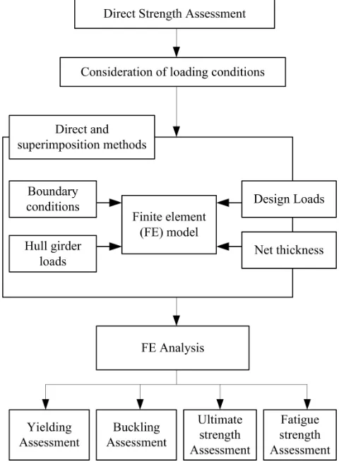
Generally, in order to solve mechanics problem by FEM, designers consider the multidiscipline component such as geometric model, material properties, size of mesh and element type, boundary conditions, combined loads. In addition, the initial imperfection and residual stress are also behaved strictly. The FEM for ship structural strength assessment flow chart is shown in Fig. 1.
Figure 1. FEM for direct strength assessment flowchart
For linear finite element analysis (FEA), MSC.NASTRAN can solve the yielding and buckling problems with good agreement. Meanwhile, the nonlinear finite element analysis (NFEM) can be performed by MSC.MARC, which is better than MSC.NASTRAN solution in this case. In new version, designer can assess the fatigue strength with Nastran Embedded Fatigue, which can be found in MSC.PATRAN 2014.
structures, etc., they are supported by frames or stiffeners in transverse direction and girder or stiffeners in longitudinal direction. In ships structures, these plates are likely to be subjected to both in-plane (including longitudinal axial compression/tension, transverse axial compression/tension, edge shear, longitudinal in-plane bending, and transverse in-plane bending) and out-of-plane loads (including cargo and water pressure are known as lateral pressure). Stiffened panels are assembly structures of ship, which they consist of welded plate and stiffeners. In elastic buckling strength and plastic collapse analysis, they are also subjected to both in-plane and out-of-plane.
Ship structures are primary importance of marine industry because they serve house and support to the systems and equipment necessary for the overall success in operation. The capability provides accurately and consistently the needed safety margin while encounter both the requirements of structural safety and economy are keys to the structural design successfully. Thus, design principles, procedures, and criteria play an important role in marine industry. In other words, it is necessary to encounter adequately the various requirements and regulations on health, safety, and the environment for assessment successful structures during their life cycle.
This study explains the buckling and ultimate strength of unstiffened plates, stiffened panel, and fatigue of FPSO crane by using MSC solutions [4].
3. Buckling and Ultimate Strength of
Ship Structures with MSC.MARC
3.1. Buckling and Ultimate Strength of Plates
In marine and aeronautical structures, various shape plates are often used which under normal compressive and shearing loads in the middle plane of the plate (in-plane loads). Plate buckling and elastic instability aspect plays an important role when a plate under certain conditions such loads can result in a plate buckling. The thickness as well as the slenderness of plates affects the buckling load for example the thinner the plate, the lower is the buckling load. The plate buckling analysis take an important part in general analysis of structures due to the failures of plate elements in many cases, may be attributed to an elastic instability and not to the lack of their strength [5,6].
A plate is an element basically of a continuous stiffened-plate structure which is subjected to study in the elastic buckling by means of analytical solution and the carried experiment. Along the longitudinal stiffener/girder and transverse frame/stiffener edges is the boundaries of a plate, it can be seen the support members, thus implying that the rotational restraints at the plate edges are neither zero nor infinite. In ships and offshore structures, there are many literatures shown that the plates are likely to be subjected to both out-of-plane and in-plane loads. The lateral pressures that caused by cargo and/or water pressure are specified as out-of-plane loads. The present of such longitudinal axial compression/tension, transverse axial compression/tension,
edge shear, longitudinal in-plane bending, and transverse in-plane bending are specified as in-plane loads. It is necessary noted that buckling does not occur in plates under axial tension or out of-plane actions alone, but rather it occurs through the application of compressive loads. The model of unstiffened plates is shown in Fig. 2.
Figure 2. Buckle shape of long plate.
According the ISSC 18th, many laboratories perform the same an un-stiffened plate model, which using the difference of solutions. For example, Pusan National University (PNU) uses ALPS/ULSAP, Det Norske Veritas (DNV) uses DNV/PULS, Indian register of Shipping (IRS) using ANSYS, and Osaka University (OU) apply MSC.MARC solution for NFEA [7]. The principle dimension of plate model is shown in Fig. 3. Material and section properties of plate are described as follows,
Yield stress of plate: σYP = 313.6 N/mm2 Elastic modulus: E = 205800 N/mm2 Poisson's ratio: ν = 0.3
Plate length: a = 2550mm Plate breath, b = 850 mm
Plate thickness: tp = 9.5; 11; 13; 16; 22; 33 mm
Figure 3. Unstiffened plate candidate analysis.
Figure 4. Results of benchmark on unstiffened plates
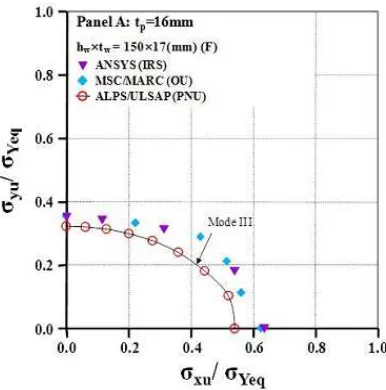
3.2. Buckling and Ultimate Strength of Stiffened Panel
The bottom of stiffened panel (panel A) a bulk carrier is analytically performed, with 4 sizes (size 1, size 2, size 3, size 4) are illustrated in Tab. 1 and Fig.6 [7]
Table 1. Dimension of stiffened panel
Flat bar (hw x tw) Angle bar Tee bar
Size 1 150x17 138x90x9/12 138x90x9/12
Size 2 250x25 235x90x10/15 235x90x10/15
Size 3 350x35 383x100x10/17 383x100x10/17
Size 4 550x35 580x150x15/20 580x150x15/20
The material, dimension and properties are described in Fig.5 as follow,
Yield stress of plate: σYP = 313.6 N/mm2 Yield stress of stiffeners: σYs = 313.6 N/mm2 Elastic modulus: E = 205800 N/mm2 Poisson's ratio: ν = 0.3
Plate length: a = 2550mm
Plate breath, b = 850 mm
Plate thickness: tp = 9.5; 11; 13; 16; 22; 33 mm For NFEA under biaxial loading Pusan National University (PNU) uses ALPS/ULSAP, Det Norske Veritas (DNV) uses DNV/PULS, University of Liege (ULG) and Indian register of Shipping (IRS) using ANSYS, and Osaka University (OU) apply MSC.MARC solution for NFEA.
Figure 5. Stiffened panel in NFEA
Figure 6. Nomenclature of Stiffened panel
The stiffened panel under biaxial compressive load with effect of initial deflection, the obtained result is illustrated in Fig.7-10,
Figure 8. Stiffened panel with angle bars size 2
Figure 9. Stiffened panel with tee bars size 3
Figure 10. Stiffened panel with tee bars size 4
In this section, the ultimate strength of stiffened panel is regarded, in which the interaction between the plate elements and support members. Their ultimate strength, buckling, and plastic collapse patterns depend on geometrical and material properties and other factors such as loading condition and initial imperfections. The possible collapse modes of a stiffened panel can be summarized into the following six types as,
- Collapse mode I: Overall collapse of plates and stiffeners as a unit;
- Collapse mode II: Biaxial compressive collapse without failure of the stiffeners;
- Collapse mode III: Collapse of beam-column type; - Collapse mode IV: Buckling stiffener web locally (after
the origin of the buckling collapse of plate between the stiffeners);
- Collapse mode V: Flexural–torsional buckling or tripping of the stiffeners;
- Collapse mode VI: Gross yielding.
A single stiffener is attached to plate, the equivalent yield stress is determined as follows,
(
)
(
)
+
+
=
+
+
Yp w w f f Ys Yeq
w w f f
bt
h t
b t
bt
h t
b t
σ
σ
σ
(1)As stiffeners are flat bar, the different values of derived results in collapse mode III between ANSYS and MSC.MARC is negligible, it is shown in Fig.7. As stiffeners are angle bar this difference is negligible between three solutions, see Fig. 8. Additionally, tee bar model is considered in Fig.9 and Fig. 10, the ratio of σxu/σYeq and σyu/σYeq in collapse mode II, III and IV is small. Generally, the reliability of MSC.MARC is good agreement in NFEA of unstiffened plate and stiffened panels.
4. Analysis of FPSO crane with MSC.
NASTRAN Embed Fatigue Solution
Figure 11. Selected location for fatigue estimation
applicable for ensuring robust design under the consideration of nonlinear environmental effects, were carried out. In order to investigate the effects of dynamic loading, the boundary conditions of an offshore platform crane having a lifting capacity of 100 tons were studied. In the finite volume method, a series of analyses were carried out using the computational fluid dynamics code, FLUENT. The crane's weight, maximum lifting load, calculated wind pressure and boundary conditions such as the inclination of the deck due to the extreme roll motion of FPSO were also considered in the finite element analyses using the commercial code, MSC/NASTRAN. Deformation, stress distribution, as well as fatigue life estimation were conducted under the unified computational environment. An advanced procedure for evaluating design concept validation was proposed for the application of FPSO design and construction. The selected location for fatigue
estimation is shown in Fig. 11, the local meshes of hot-spot stress evaluation for fatigue estimation is shown in Fig.12.
Figure 12. Local meshes of hot-spot stress evaluation
Table 2. Analysis scenarios
Case no Gravity Lifting load Dynamic factor Wind loads Rolling inclination Direction of offshore crane
1 0 - - - -
2 0 100 tons 1.8 - -
3 0 100 tons - 18 m/s -
4 0 100 tons - 30 m/s -
5 0 100 tons 1.8 18 m/s -
6 0 100 tons 1.8 -
7 0 100 tons 1.8 -
8 0 100 tons 1.8 30.6 Crosswise (port)
9 0 100 tons 1.8 30.6 Crosswise (st. board)
10 0 100 tons 1.8 30.6 Lengthwise
By using MSC.NATRANS solution, the FPSO crane model is calculated in 10 load cases, the obtained result is shown in Tab.3. Failure is assumed to occur when the accumulated damage is equal to 1. Assuming that the crane has 20 years of lifetime, the number of applied load cycles is shown in Tab.3.
The obtained values of accumulated fatigue damage at the interest locations are calculated being less than 1.0. This means that the crane is still safe against fatigue failure at the two locations for 20 years.
Table 3. Summary of resultant stress (MPa)
Case no Max stress Boom part 1 Boom part 2 King post Pedestal
1 107 81.6 28.6 107 87.2
2 333 267 27.4 333 279
3 485 395 31.8 485 447
4 323 257 29.5 323 282
5 381 248 33 318 297
6 531 421 32.5 531 450
7 514 405 34.5 514 465
8 384 332 31 384 284
9 485 401 28.4 451 485
10 681 596 77.9 681 488
5. Conclusion
This paper discussed the performance of MSC solutions with NASTRAN and MARC for ship structural analysis. The results are obtained from reports of ISSC 18th and Han et al. It is proved the advanced of MSC solution is complying with linear finite analysis as well as nonlinear finite analysis. These solutions play an important role in assessment of strength, buckling, ultimate limit state and fatigue.
References
[1] O. F. Hughes, Paik, J.K., Béghin, D., “Ship structural analysis and design”. Jersey City, N.J.: Society of Naval Architects and Marine Engineers, 2010.
[3] Y. Okumoto et al., “Design of ship hull structures : A practical guide for engineers”. Berlin ; London: Springer, 2009.
[4] MSC, “Patran 2014 Interface To MSC Nastran Preference Guide Volume 1: Structural Analysis”, MSC, 2014.
[5] Paik et al., “Methods for ultimate limit state assessment of ships and ship-shaped offshore structures: Part I—Unstiffened plates”. Ocean Engineering, 2008. 35(2): p. 261-270.
[6] Paik et al., “Methods for ultimate limit state assessment of
ships and ship-shaped offshore structures: Part II—Stiffened plates”. Ocean Engineering, 2008. 35(2): p. 271-280.
[7] ISSC, "Committee III.1: Ultimate Strength," in 18th International ship and Offshore structure congress, Rostock, Germany, 2012, pp. 285-363.
[8] Han, D.-S., et al., “Coupling analysis of finite element and finite volume method for the design and construction of FPSO crane”. Automation in Construction, 2011. 20(4): p. 368-379.
Biography
Hung-Chien DO (1978, Hai Phong,
Vietnam). He obtained Bachelor’s Degree in Ship Design and Master’s Degree in Ship Engineering from Vietnam Maritime University in 1996 and 2007, respectively. He got PhD degree in School of Mechanical Science and Engineering (2014, Huazhong University of Science and Technology, Wuhan, China).
Dr Do is Head of Ship Mechanics Department, Faculty of Naval Architecture in Ho Chi Minh City University of Transport, Vietnam. Research experience: Ship mechanics, Ship structural design, Ship longitudinal strength, Plate and stiffened panel strength, Ultimate strength of ship structures. He is an author of 3 journal and conference papers in the field of Ship structural buckling and ultimate strength.
Vo Trong CANG (1961, Saigon). Senior lecturer of the Faculty of Transportation Engineering at the Ho Chi Minh city University of Technology (HCMUT), Vietnam National University of Ho Chi Minh city (VNU-HCM). Research fields: maintenance optimization and 3D modeling in ship construction.