DIGITAL CLOCK USING AT89C51
K.Geeth Vimal Kumar1*, G.Shruthi2, N. Uma Sundari3, G.Vivek4, P.Manivara Kumar5
1*234B.Tech Students, Dept of ECE, CIET,Lam, Guntur,India 5Assistant Professor, Dept of ECE, CIET,Lam, Guntur,India
Correspondence Author: [email protected]
Keywords:Digital Clock; LCD Display; AT89C51; 8051Microcontroller
Abstract
In this Project, a Digital clock is designed where the microcontroller is used for timing controller and the programming is a lso done in the microcontroller. The design is cost effective, simple and easy for maintenance.
A clock is an instrument for measuring time. In principle it requires no more than some physical process which will proceed at a known rate, and a way to gauge how long that process has been continuing.
Digital clocks display a numeric representation of time. Two numeric display formats are commonly used on digital clocks. They are: 24-hour notation with hours ranging 00 to 23 and 12 hour notation with AM/PM indicator. Most digital clocks use an LCD or LED display.Generally for the designing a digital clock, a microcontroller is used as the controller of the circuit and a Real Time Clock IC is used as counter.
Our approach is to simulate the clock circuitry in Proteus 8.1 software with all the necessary interfacing connection and program. After simulating in the Proteus, we move to hardware implementation of the Digital clock.
Introduction
Electronic clocks are widely used instead of Mechanical Clocks. The reason is Digital clocks are portable reliable, accurate and maintenance free. Digital clocks are more common and independent of external source. To implement a Digital Clock, we require software. Microcontroller control system will use this software for its functioning. This Paper will describe how we have constructed the microcontroller based Digital Clock is constructed with ATMEL 89C51.
AT89C51
The Chip we use is AT89C51. AT89C51 is an 8-bit microcontroller which belongs to Atmel's 8051 family. We use 4KB of Flash present in AT89C51 to place our program hex file. This is erasable read only memory (PEROM). It also has 128bytes of RAM. AT89C51 is a 40 pin device and it has four ports designated as P1, P2, P3 and P0. All these ports are 8-bit ports and can be used as both input and output ports. Except P0 which needs external pull-ups, rest of the ports have internal pull-ups. When 1s are written to these port pins, they are pulled high by the internal pull-ups and can be used as inputs. These ports are also bit addressable and so their bits can also be accessed individually.
Port P0 and P2 are also used to provide low byte and high byte addresses, respectively, when connected to an external memory. Port 3 has multiplexed pins for special functions like serial communication, hardware interrupts, timer inputs and read/write operation from external memory. AT89C51 has an inbuilt UART for serial communication. It can be programmed to operate at different baud rates. Including two timers & hardware interrupts, it has a total of six interrupts.
LCD display
A Liquid-Crystal Display (LCD) is a flat panel display, electronic visual display, or video display that uses the light modulating properties of liquid crystals. Liquid crystals do not emit light directly. LCDs are available to display arbitrary images (as in a general-purpose computer display) or fixed images with low information content which can be displayed or hidden, such as preset words, digits, and 7-segment displays as in a digital clock. They use the same basic technology, except that arbitrary images are made up of a large number of small pixels, while other displays have larger elements. LCDs are used in a wide range of applications including computer monitors, televisions.
A Liquid crystal display is a special thin flat panel that can let light go through it, or can block the light. (Unlike an LED it does not produce its own light). The panel is made up of several blocks, and each block can be in any shape.
Liquid crystal displays are often used in battery-powered devices, such as digital watches, because they use very little electricity. They are also used for flat screen TV's. Many LCDs work well by themselves when there is other light around (like in a lit room, or outside in daylight). For smartphones, computer monitor, TV's and some other purposes, a back-light is built into the product.Some passive matrix LCD's have dual scanning, meaning that they scan the grid twice with current in the same time that it took for one scan in the original technology. However, active matrix is still a superior technology.
Fig.2. LCD Display
They are common in consumer devices such as DVD players, gaming devices,clocks,watches,calculators, and telephones, and have replacedcathode ray tube(CRT) displays in nearly all applications. They are available in a wider range of screen sizes than CRT andplasma displays, and since they do not use phosphors, they do not suffer image burn-in. LCDs are, however, susceptible toimage persistence. The LCD screen is more energy efficient and can be disposed of more safely than a CRT. Its low electrical power consumption enables it to be used in battery-powered electronic equipment. It is anelectronically modulated optical devicemade up of any number of segments controlling a layer ofliquid crystalsand arrayed in front of alight source(backlight) orreflectorto produce images in colour or monochrome. Liquid crystals were first discovered in 1888.By 2008, annual sales of televisions with LCD screens exceeded sales of CRT units worldwide, and the CRT became obsolete for most purposes.
Interfacing AT89C51 with LCD display
The Circuit diagram given above shows how to interface a 16×2 LCD module with AT89S1 microcontroller. Capacitor C3, resistor R3 and push button switch S1 forms the reset circuitry. Ceramic capacitors C1,C2 and crystal X1 is related to the clock circuitry which produces the system clock frequency. P1.0 to P1.7 pins of the microcontroller is connected to the DB0 to DB7 pins of the module respectively and through this route the data goes to the LCD module.
Fig3. Interfacing of AT89C51 with LCD Display
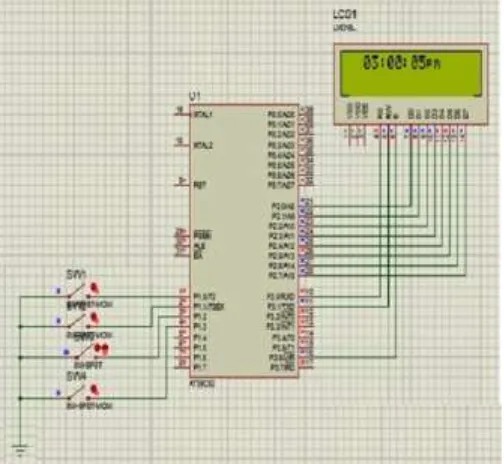
Simulation of digital clock in proteus
Connections are made as shown in the circuit diagram below. Then we developed the program and run in Keil to obtain the hex file after debugging . We open this hex file in the AT89C51. We can check whether our program is working. After conforming this we then go for the connecting the discrete components.
Fig4. Circuit Diagram showing all connections
The following steps of connections are followed.
STEP1: PINS 28-21 of the microcontroller are connected to the PINS 7-14 of the LCD display. STEP2: PINS 16,11,10 of the microcontroller are connected to the PINS 4,5,6 of the LCD display. STEP3: PINS 18,19 of the microcontroller are connected to the oscillator.
STEP4: PINS 1,2,3 of the microcontroller are connected to the switches S1,S1,S3. STEP5: PINS 1,2,3 of the microcontroller are also connected with resistors R1,R2,R3.
Hardware implementation of digital clock
The power is supplied to components like regulator, resistors and Microcontroller control circuitry using a 12V/3.2A battery and microcontroller requires 5V .with the help of regulators we regulate the power between three components. This Clock works in 12 hour mode and is configured by programming the microcontroller AT89C51. The program uses a delay function for producing a delay of 1 second.
Fig 5. Simulation of Digital Clock circuit in Proteus software.
Fig 6. Implementation of Digital Clock on Breadboard.
It is designed to adjust the time whenever it is powered ON. The Fig 7 clearly shows the system is asking to set the time. We can also set AM or PM. As shown in Fig 6.
Conclusion
References
1. Vishay electronic gmbh, 16 x 2 Character LCD datasheet http://www.vishay.com/docs/37294/37294.pdf 2. Atmel corporation, Atmel AT89C4051 datasheet. http://www.atmel.com/images/doc0265.pdf
3. Mcs electronics, BASCOM-AVR. http://mcselec.com/index.php?option=com_content&task=view&id=14&Itemid=41 4. Dallas semiconductor, DS12885 Real Time ClockData sheet
http://www.embeddedsys.com/subpages/resources/images/documents/DS12885_datasheet.pdf 5. www.8051projects.com