www.nonlin-processes-geophys.net/13/377/2006/ © Author(s) 2006. This work is licensed
under a Creative Commons License.
Nonlinear Processes
in Geophysics
Experimental study of nonlinear interaction of plasma flow with
charged thin current sheets: 2. Hall dynamics, mass and
momentum transfer
S. Savin1, E. Amata2, M. Andre3, M. Dunlop4, Y. Khotyaintsev3, P. M. E. Decreau5, J. L. Rauch5, J. G. Trotignon5, J. Buechner6, B. Nikutowski6, J. Blecki7, A. Skalsky1, S. Romanov1, L. Zelenyi1, A. M. Buckley8, T. D. Carozzi8, M. P. Gough8, P. Song9, H. Reme10, A. Volosevich11, H. Alleyne12, and E. Panov6,1
1Space Research Institute, 117997, Profsoyuznaya 84/32, Moscow, Russia 2Istituto di Fisica dello Spazio Interplanetario, INAF, Roma, Italy
3Swedish Institute of Space Physics, Uppsala, Sweden
4Space Science and Technology Department, Rutherford Appleton Laboratory, UK 5Laboratoire de Physique et Chimie, de l’Environnement, CNRS, Orl´eans, France, France 6Max-Planck-Institut fur Sonnensystemforschung, Katlenburg-Lindau, Germany
7Space Research Center, Polish Academy of Sciences, Warsaw, Poland 8Space Science Centre, University of Sussex, UK
9University of Massachusetts, Lowell, USA
10Centre d’Etude Spatiale de Rayonnement, CNRS/UPS/OMP, Toulouse, France 11Mogilev State University, Belarus
12Control and Systems Engineering, University of Sheffield, UK
Received: 3 May 2005 – Revised: 23 March 2006 – Accepted: 23 March 2006 – Published: 10 August 2006 Part of Special Issue “Nonlinear and multiscale phenomena in space plasmas”
Abstract. Proceeding with the analysis of Amata et
al. (2005), we suggest that the general feature for the lo-cal transport at a thin magnetopause (MP) consists of the penetration of ions from the magnetosheath with gyroradius larger than the MP width, and that, in crossing it, the trans-verse potential difference at the thin current sheet (TCS) is acquired by these ions, providing a field-particle energy ex-change without parallel electric fields. It is suggested that a part of the surface charge is self-consistently produced by deflection of ions in the course of inertial drift in the non-uniform electric field at MP.
Consideration of the partial moments of ions with dif-ferent energies demonstrates that the protons having gyro-radii of roughly the same size or larger than the MP width carry fluxes normal to MP that are about 20% of the total flow in the plasma jet under MP. This is close to the ex-cess of the ion transverse velocity over the cross-field drift speed in the plasma flow just inside MP (Amata et al., 2005), which conforms to the contribution of the finite-gyroradius inflow across MP. A linkage through the TCS between differ-ent plasmas results from the momdiffer-entum conservation of the Correspondence to: S. Savin
higher-energy ions. If the finite-gyroradius penetration oc-curs along the MP over∼1.5RE from the observation site,
then it can completely account for the formation of the jet under the MP. To provide the downstream acceleration of the flow near the MP via the cross-field drift, the weak magnetic field is suggested to rotate from its nearly parallel direction to the unperturbed flow toward being almost perpendicular to the accelerated flow near the MP.
We discuss a deceleration of the higher-energy ions in the MP normal direction due to the interaction with finite-scale electric field bursts in the magnetosheath flow frame, equiva-lent to collisions, providing a charge separation. These effec-tive collisions, with a nonlinear frequency proxy of the order of the proton cyclotron one, in extended turbulent zones are a promising alternative in place of the usual parallel electric fields invoked in the macro-reconnection scenarios. Further cascading towards electron scales is supposed to be due to unstable parallel electron currents, which neutralize the po-tential differences, either resulted from the ion- burst interac-tions or from the inertial drift.
378 S. Savin et al.: Experimental study of nonlinear interaction of plasma flow 2 The measured Poynting vector indicates energy
transmis-sion from the MP into the upstream region with the waves triggering impulsive downstream flows, providing an input into the local flow balance and the outward movement of the MP.
Equating the transverse electric field inside the MP TCS by the Hall term in the Ohm’s law implies a separation of the different plasmas primarily by the Hall current, driven by the respective part of the TCS surface charge. The Hall dynamics of TCS can operate either without or as a part of a macro-reconnection with the magnetic field annihilation.
1 Introduction
We proceed with analysis of the transport processes and mechanisms for plasma jet acceleration at a thin current sheet (TCS,∼90 km thick) observed on 13 February 2001, at ∼20:01 UT, which has been identified with the magne-topause (MP) in the companion paper Amata et al. (2005), cited as [A] hereafter, where the Cluster data used and the respective instrumentation are described. Via the ion finite-gyroradius effect, the TCS with a potential jump ∼300 V provides a partial mass and momentum transfer and energy conversion [A]. From 3 timing differences between the elec-tric field measurements from all Clusters at MP, on a 2-min time scale, a constant MP velocity is foundVMP=(26.2; 0.2;−15.7) km/s in GSE, while MP normals from minimum variance analysis of magnetic field yieldsNB=(0.96,−0.21,
−0.16) at∼25◦fromVMP. At shorter time scales of∼10 s at the MP the constant-velocity (CVA, see Haaland et al., 2004) and minimum variance approaches are inconsistent with ion low-energy cutoffs. Maximum variance analysis for the elec-tric field gives common normal NE=(0.95, −0.3, 0.087),
which is at 16◦to theN
B, and at 40◦theVMP. Constant MP thickness approach (CTA, see Haaland et al., 2004) gives a normalNCTA∼(0.815, 0.579, 0.02) and speeds for Cluster 1, 2, 3, 4: VCTA∼41; 35; 43; 33 km/s. The averageVCTA magnitude lies in a 21% window fromVMP[A].
In this paper we propose an explanation for the different directions of the local normal from both minimum variance of the magnetic field and from maximum variance of the electric field versus direction of the MP motion from the ob-served time delays on 4 spacecraft (cf. Dunlop et al., 2005), suggesting that the motion of an indented MP is defined by non-local properties of the near-cusp region as an entity. We compare the difference between ion velocity and the cross-field drift velocity, demonstrating a systematic deficit of the drift speed of∼25% only in the tailward plasma jet just in-side the TCS [A], with the plasma inflow in the MP normal direction due to the finite-gyroradius effect. We show the necessary extra Cluster 1 data and apply the results of multi-point analysis from [A] for the scale estimation and plasma current calculations.
The Hall dynamics of a thin MP current sheet is out-lined. Previous studies of data from Interball-1, Polar and Cluster (Nikutowski et al., 1998, 1999; Mozer et al., 2003a; Vaivads et al., 2004) have been mostly limited to the com-parison with models of stationary X-line macro reconnec-tion. In the TCS the frozen-in condition is violated due to the small current scale, which can be described not only in reconnection-like approximations, but also in terms of gyro-viscosity (Stasiewicz, 1994; Sibeck et al., 1999). Belmont and Rezeau (2001) use the term “micro reconnection” for similar effects of Alfven waves on the magnetic flux erosion. The Hall dynamics of the charged TCS, might include tran-sient (and multiple) X-, Y-, O-lines etc. as particular scenar-ios for the current sheet evolution (see e.g. Syrovatskii, 1971; Sibeck et al., 1999; Zelenyi et al., 2002; Silin and Buechner, 2003; Savin et al., 2004b, 2005a). For a simple model Mozer et al. (2003) demonstrate that the Hall dynamics per se can explain local plasma structuring without local reconnection features (e.g. parallel electric fields and electron diffusion re-gions). We propose that electrons with large thermal speeds can provide surface charges at the TCS moving along field lines. The surface charges support transverse diamagnetic currents, separating different plasmas via the Hall effect (cf. Mozer et al., 2003). In turn, the potential difference for driv-ing the field-aligned electron current might result from iner-tial drift of the incident (MSH) ions in the non-uniform elec-tric field of the surface charge, seen in the frame of bulk mo-tion by the MSH plasma; and the inertial drift results in ion separation from electrons (cf. Genot et al., 2004; Savin et al., 2004a, 2005a). Recent papers, claiming crossings of a diffu-sion region (e.g. Vaivads et al., 2004; Mozer et al., 2003a), in reality confirm the Hall ion dynamics in TCS and show the existence of substructures of electron-gyroradius (inertial-length) scales, the presence of which automatically implies breaking of frozen-in conditions for electrons (cf. Savin et al., 1998; Andre et al., 2004). Those features naturally are present in reconnection models, while they are also charac-teristic of a kinetic TCS without reconnection (see e.g. Silin and Buechner, 2003). Filamented electron beams of elec-tron scales also account for the neutralization of the potential difference, generated by the charge separation through iner-tial drift (Genot et al., 2004). The ineriner-tial drift in standing electric wave-packets at the outer border of the MP bound-ary layer is able to accelerate structured jets up to magne-tosound and highly super-Alfvenic velocities, and the jet dy-namic pressure can largely exceed that of the magnetic one at a downstream MP (Savin et al., 2004a, 2005b).
into the dynamics, mass and momentum balance at MP. It is demonstrated that the finite-gyroradius effect can account for a substantial mass and momentum transfer across MP. We suggest a non-reconnection mechanism for the formation of plasma streams near MP: the larger-energy ions conserve their momentum parallel to MP during the motion across MP in the high-beta plasma, resulting in the motion of the in-ner plasma without an annihilation of the magnetic field, i.e. without the macro reconnection, the effects of which could be superimposed or not.
2 Plasma inflow and momentum balance
In [A] it has been demonstrated that the largest flow bursts near the MP (i.e. jets, see Fig. 1 of [A] at∼19:30, 19:50 and 20:01 UT) occur perpendicularly to the magnetic field direction in contrast to the Gas Dynamic Convection Field (GDCF) model prediction and to unperturbed nearly parallel flows (see [A] and Savin et al., 2002 for the GDCF descrip-tions). Thus the perpendicular flows are of general impor-tance for the mass and momentum balance in the MP vicinity. To estimate how finite-gyroradius effects affect the flow bal-ance near the MP, in [A] the drift velocityVd=E×Bis
com-pared withVperp, i.e. the ion velocity perpendicular to the magnetic field (see Fig. 8 in [A]). For the enhanced plasma flow just inside MP at 20:00:50–20:02:00 UT (called “MP jet”) [A] roughly estimate that Vperp is higher than Vd by
25%.
To facilitate further analysis of the thin nonlinear structure, TCS, we calculate the partial moments for ions with energy larger than a chosen value in the spacecraft frame. However this might pose certain errors as we cannot calculate these moments in a plasma bulk frame for two reasons: (i) the flow velocity changes much on each time step of 4 s, while we need to compare the input in the flow from ions with dif-ferent energies over the interval of several minutes; (ii) the plasma appears to be a non-equilibrium one with co-existing ion populations with different moments (see Figs. 3, 2 and 6–7 in [A] and related discussion in [A]), that, in principle, requires extracting separate moments for each ion popula-tion and a comparison with respective multi-fluid equapopula-tions (planned for a future paper).
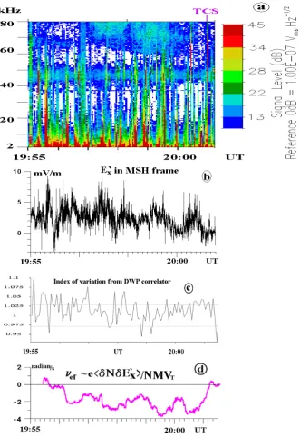
Figure 1 displays, in the top panel, the total ion number density (thin blue curve), compared with the GDCF predic-tion (thick gray line), along with partial ion number densities, for energies larger than 300 eV (black) and 1 keV (red). The bottom panel shows theEx electric component (green) and
its GDCF predictions (dark blue line). Finally, Inserts A and B, illustrate the rotation of the magnetic field vector in the presence of a regular difference betweenEx and its GDCF
proxy. In general the total ion density follows the GDCF one until∼19:50 UT, when the total density starts to fluctuate and finally drops at∼20:07 UT toward the mantle value. At the innermost edge of the “diamagnetic cavity” before 20:07 UT
Fig. 1. Cluster-1, February 13, 2001. Top panel: Ion density (blue) near the MP entry (~ 20:01 UT); that of model GDCF (grey), for ions with energy > 300 eV (black), > 1 keV (red); electric field component Ex in spacecraft frame (green) and that of GDCF (thick blue line).
Bottom inserts: Insert A – scheme for ion velocity Vi (violet arrow) and magnetic field (black arrow) in unperturbed flow around MP, electric field in the flow frame is negligible; Insert B – that of the flow, disturbed by the ‘active’ DC electric field (marked by ‘En’, blue arrows) along the MP normal, note rotation of the magnetic field and acceleration of the flow.
Fig. 1. 13 February 2001. Top panel: Cluster 1 ion density (blue)
near the MP entry (∼20:01 UT); GDCF density (grey), Cluster 1
density for ions with energy>300 eV (black),>1 keV (red).
Bot-tom panel: ClusterExin spacecraft frame (green) and GDCFEx
(thick blue line). Insert A – scheme for ion velocityVi (violet
ar-row) and magnetic field (black arar-row) in unperturbed flow around MP, when the electric field in the flow frame is negligible; Insert B – scheme of the flow disturbed by the “active” DC electric field
(marked by “En”, blue arrows) along the MP normal. Note the
ro-tation of the magnetic field and the acceleration of the flow.
(cf. Fig. 1 in [A]) dense cold plasma appears again, flowing now generally along field lines from an upstream outer cusp. Inside the region of density fluctuations (19:50–20:07 UT) ions of>1 keV are intensified, having maxima at 19:50 and 20:01 UT (cf. Fig. 1 in [A]). The latter is just inside MP, pre-ceded by the sharp maximum of the total density outside MP, which corresponds to MSH flow, piled up by the MP outward motion at∼35 km/s. Density of ions with energy>300 eV generally follows the total density outside MP and the den-sity of the more energetic ions inside MP. After 19:50 UT density of ions with energy>1 keV grows presumably due to escaping of the ions with finite-gyroradius from the cusp [A] and to probable wave-particle interactions, which can be inferred from correlations between the density departures from GDCF and fluctuations ofEx(green line). The
380 S. Savin et al.: Experimental study of nonlinear interaction of plasma flow 2 Fig. 1. Cluster-1, February 13, 2001. Top panel: Ion density (blue) near the MP entry (~ 20:01 UT);
that of model GDCF (grey), for ions with energy > 300 eV (black), > 1 keV (red); electric field component Ex in spacecraft frame (green) and that of GDCF (thick blue line).
Bottom inserts: Insert A – scheme for ion velocity Vi (violet arrow) and magnetic field (black arrow) in unperturbed flow around MP, electric field in the flow frame is negligible; Insert B – that of the flow, disturbed by the ‘active’ DC electric field (marked by ‘En’, blue arrows) along the MP normal, note rotation of the magnetic field and acceleration of the flow.
Fig. 2. Cluster-1, February 13, 2001. (a): ion flux ‘nVix’, blue lines – full CIS energy range (see [A]), black – partial ion flux for > 300 eV, red – for > 1keV ions; (b) the same for ‘nViy’; (c) the same for ‘nViz’; (d): ion density ni (blue), partial ion density for energies > 300 eV (black), that of > 1 keV (red) and full ion flux (cyan line, the jet is marked by shadowing, see text for details).
Fig. 2. Cluster-1, February 13, 2001. (a): ion flux ‘nVix’, blue lines – full CIS energy range (see [A]), black – partial ion flux for > 300 eV, red – for > 1keV ions; (b) the same for ‘nViy’; (c) the same for ‘nViz’; (d): ion density ni (blue), partial ion density for energies > 300 eV (black), that of > 1 keV (red) and full ion flux (cyan line, the jet is marked by shadowing, see text for details).
Fig. 2. Cluster-1, February 13, 2001. (a): ion flux ‘nVix’, blue lines – full CIS energy range (see [A]), black – partial ion flux for > 300 eV, red – for > 1keV ions; (b) the same for ‘nViy’; (c) the same for ‘nViz’; (d): ion density ni (blue), partial ion density for energies > 300 eV (black), that of > 1 keV (red) and full ion flux (cyan line, the jet is marked by shadowing, see text for details).
Fig. 2. Cluster-1, 13 February 2001. (a) ion flux “nVix”, blue
lines – full CIS energy range (see [A]), black – partial ion flux for
>300 eV, red – for>1 keV ions; (b) the same for “nViy”; (c) the
same for “nViz”; (d): ion densityni (blue), partial ion density for
energies>300 eV (black), that of>1 keV (red) and full ion flux
(cyan line, the jet is marked by shadowing, see text for details).
Insert A of Fig. 1 shows the mutual orientation of the ion flow velocityVi (violet), magnetic fieldB(black) and MP in
the unperturbed MSH flow:ViandBare nearly parallel,
con-forming to the GDCF model predictions. Insert B shows the actual situation in the case under study. The presence of the bipolar normal electric fieldEn(blue) results mainly in theB
rotation and in theVi rise due to the cross-field drift (in case
of Insert A the flow acceleration byEnis impossible in the
shown plane). Thus, the rise of the downstream flow veloc-ity described in Fig. 4 of [A] (cf. also Fig. 4 herein) should be the consequence not only ofEn, but also of the forced
magnetic field rotation. Namely this magnetic field rota-tion makes the flow transverse, at∼19:56–19:58 and 20:01– 20:02 UT (see 3rd panel from bottom in Fig. 1 of [A]).
Figure 2 displays, in the bottom panel, the CIS-HIA proton number density (blue line) and the number density for pro-tons with energy higher than 300 eV and 1 keV (black and red line respectively). The last curve in the bottom panel shows the total proton flux (cyan line). The remaining pan-els display the three components of proton flux, calculated for the full distribution (blue line) and for energies greater 300 eV and 1 keV (black and red lines respectively). The maximum of the lower-energy ions, which are reflected by the MP TCS (see Fig. 2 in [A]), at ∼20:00:53 UT infers placing their source outside the MP. In this region the ion flux is carried by the colder ions, as one can see in panels a-c from the difference between the blue and black curves. The large-gyroradius ions (energy >1 keV, red lines) carry up to 60% of the flux in the jet inside MP. Note inward large-gyroradius flownVix (panel a), which constitutes∼20% of
the total flow in the inner jet. The ions, carrying this in-ward flux, should not feel the small-scale (<their gyrora-dius) MP current sheet, i.e. the higher-energy flux gives the lower-limit estimate for the local influx. The intermediate-energy ions (marked black) could also provide an input into the inflow, while the minimum influx at 20:00:54 UT is de-fined largely by the large-gyroradius influx. At the magne-tospheric border of the inner jet (after 20:02 UT) there is a vanishing X-component of inflow (the normal from magnetic field minimum variance NB is close to X, see [A]). Thus
from the necessary mass-conservation in an almost incom-pressible plasma, we suggest that this inflow provides a local source for the jet inside the MP. Its minimum contribution (estimated above as∼20%) agrees fairly well with∼25% of the ion velocity (Vperp)excess over the electric-drift veloc-ity (Vd)in Fig. 8 from [A]. Taking the estimate for width of
the inner plasma jet∼2000 km (cf. [A]), one obtains a proxy for the scale along MP of∼1.5RE, at which the jet can be
formed uniquely by the inflow from finite-gyroradius effects (providing similar MP structure upstream from the Cluster crossing). The 1.5REis almost one half of the characteristic
dimension along MP of “plasma balls” (Savin et al., 2005a); thus we regard the finite-gyroradius effect as a major plasma source for the inner jet. An interesting feature in Fig. 2, is the conservation of the dominant nVz flux (panel c) across
the MP for ions with energy>300 eV. These protons with gyroradius of roughly the same size or larger than the MP width carry the major ion flux on both sides of the MP.
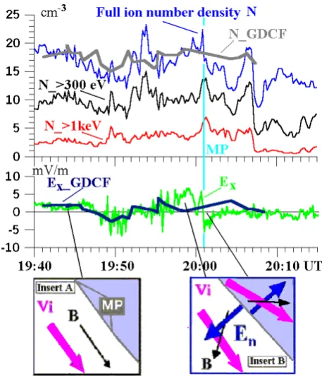
Fig. 3. 4 s resolution CIS 2 omni-directional differential fluxes as a function of energy, Cluster 1, February 13, 2001 See text for details). Fig. 3. 4 s resolution CIS 2 omni-directional differential fluxes as a
function of energy, Cluster 1, 13 February 2001 See text for details).
Fig. 3 displays the omni-directional Cluster 1 spectra from 19:48:49 to 19:49:44 UT from the leading edge of an event of departure of electric field, clock-angle and By from the
GDCF predictions at ∼19:50 UT (see Fig. 1 and Fig. 1 of [A]). For reference, we plotted a spectrum measured just ahead the MP TCS (in red, marked by “200056 UT”, see Fig. 4 in [A]) and a characteristic spectrum inside the jet at 20:01:29 UT (in black). Inspection of 3D ion distributions (not shown) shows that higher-energy protons arrive paral-lel to the magnetic field, i.e. from an upstream region along the MP. We marked by different colors 3 consecutive spec-tra at 19:48:56, 19:49:04 and 19:49:04 UT, which we use to estimate the distance from a source of heated proton using time-of-flight methodics (see e.g. Sibeck et al., 1999).
This yields a distance of 2–3RE, which implies that the
plasma source is at a side of the cusp throat rather than at the position of the dayside anti-parallel magnetic fields across MP, where the large-scale reconnection should occur for the measured southward IMF (∼5–6RE, see Fig. 6 and related
discussions below, cf. Sibeck et al., 1999, and Cargill et al., 2004). We attribute the well seen higher-energy maxi-mum in the remaining spectra from the interval 19:49:04– 19:49:44 UT to the penetration of the heated ions from the boundary layer inside cusp due to the finite-gyroradius effect (cf. Figs. 4, 6 in [A]). In such case the MP width might be remotely sounded along field lines: at about 19:49:04 UT the low-energy cutoff is∼3 keV that corresponds to a MP thick-ness of∼190 km (provided the similar strength and profile of magnetic field at MP); then the cutoff energy evolves to-wards 2 keV, which suggests a MP width of∼160 km. Thus, the estimated distance from the ion leakage event suggests widespread ion-gyroradius effect that in turn is a sign of its
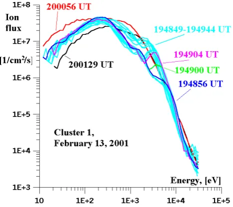
Fig. 4. Cluster-1, February 13, 2001. (a): GSE vector of electric field (E`) in a MSH-flow frame with
VMSH = (-45, -90, -150) km/s in front of the TCS (marked by 2 vertical lines in panel b); (b):
magnetic field vector and magnitude; (c): Poynting flux (P) GSE components in spacecraft frame, calculated from electric and magnetic field cross-product after subtracting of signal, averaged by the spline procedure with 2001 points of the interpolated data with sampling at 25 Hz; P_N_B green line - Poynting flux along the average normal from magnetic minimum variance analysis NB, P_N_E -
the same along direction electric field of maximum variance NE,; (d) GSE electric drift velocity (Vd)
and ion velocity (V, dashed line) in spacecraft frame.
Fig. 4. Cluster-1, 13 February 2001. (a) GSE vector of electric field
(E0) in a MSH-flow frame withVMSH=(−45, −90, −150) km/s
in front of the TCS (marked by 2 vertical lines in panel b); (b)
magnetic field vector and magnitude; (c) Poynting flux (P) GSE
components in spacecraft frame, calculated from electric and mag-netic field cross-product after subtracting of signal, averaged by the spline procedure with 2001 points of the interpolated data with sam-pling at 25 Hz; P N B green line – Poynting flux along the average
normal from magnetic minimum variance analysisNB, P N E – the
same along direction electric field of maximum varianceNE; (d)
GSE electric drift velocity (Vd)and ion velocity (V, dashed line) in
spacecraft frame.
382 S. Savin et al.: Experimental study of nonlinear interaction of plasma flow 2 defining the coefficient of reflection for the ions being able
to cross a finite-gyroradius MP, have been introduced (see Sibeck et al., 1999).
We now consider the contributions of AC and quasi DC electric fields to the flow balance. In Fig. 4 we present GSE vectors of the electric field from Cluster 1 (panel a) in a MSH-flow frame, moving at a characteristic speed VMSH=(−45, −90, −150) km/s near the MP (see Fig. 1 in [A], cf. Savin et al., 2004a); of magnetic field (panel b); of Poynting flux (panel c, spacecraft frame); of ion velocity and of electric drift velocity (panel d, spacecraft frame). Further in the text we use the notationE0for the electric field compo-nents in the MSH frame. The unperturbedEx0 andE0yat the left side of Fig. 4 are close to zero, inferring for these com-ponents that the chosen particular value ofVMSH is a good proxy for transformation into the MSH-flow frame for the total time interval;Ez0 at the left side of Fig. 4 has a DC off-set, requiring a corresponding change of the MSH speed for the data transformation at the time interval beginning, but we neglect this offset relative to the strong disturbances, visible at 20:00:30–20:00:50 UT in Fig. 4, generally inE0x. So, the transformation into a MSH frame demonstrates that the in-cident ions are affected mainly by theE0xcomponent, which is close to the MP normal (see Introduction and discussion in [A]). Note that electric field at the TCS is diminished in this frame, but the transformation used has no explicit sense under MP, which partially reflects the incident flow and par-tially transfers it (see discussion of Figs. 2 and 4–7 in [A]).
The main input of the quasi DC electric field into the flow balance near the MP is an acceleration of the plasma down-stream, mainly in the -Z direction in front of the MP, via the cross-field drift (see panel d). The strong positiveEx0 disturbances have a local origin, in contrast to the global GDCF predictions (see Fig. 1 – green line versus thick violet trace, cf. [A]). The similarity of profiles ofVdz and
Poynt-ing flux Pz component indicates that waves accelerate the
plasma in the same direction at 20:00:25–20:00:50 UT, pre-sumably via inertial drift (see Eq. (2) below). AveragingVdz
over the interval of maximum drift (20:00:25–20:00:50 UT) gives 91 km/s with a standard deviation of 39 km/s. As this averaging includes the input of the AC spikes, we attribute ∼52 km/s to the average cross-field drift, i.e.>1/3 of the ac-celerated flow should in this case be due to the AC input. We do the crude dividing of AC and DC components by estimat-ing of average input from the waves intoVdzsimilar toPz:
its mean value is comparable with its deviation. The posi-tive projections of Poynting flux onto the normals (pointed sunward) and positivePx- spikes demonstrate that the waves
propagate upstream, being most probably reflected from the MP (cf. Belmont and Rezeau, 2001 and Savin et al., 2005a) or emitted by the jet.Vdyoutside MP is pointed in the +Y
di-rection (i.e. along the smooth MP, see Fig. 5 and related dis-cussion below), while inside MP it is along -Y-axis, presum-ably due to the opposite normal electric field from different MP sides. It appears strange that the AC disturbances (Py)
outside MP propagate in the opposite direction relative to the main outerVdy, i.e. along -Y-axis, as the waves inside MP do,
and a correlation of the latter withVy(dashed line) points to
transport of the inner disturbances downstream by the jet. As the inner disturbances have the positivePxand normal
com-ponents, they should represent a source for the outer ones. Another reason for the outlined behavior would be guiding of the smaller-scale disturbances by the cusp throat, which has the opposite curvature compared to that of the smooth MP (see Fig. 5 and discussions below). We have checked that the Poynting flux and drift velocity behave similarly to that of Fig. 4 at 20:00:32–20:00:50 UT since∼19:56 UT, i.e. whenExdeparts from the GDCF predictions (see Fig. 1).
3 MP shape, motion and charging
In this section we discuss possible applications and conse-quences of finite-gyroradius effects and the local DC and AC electric fields, described above, to transport processes and MP dynamics.
The picture of the global configuration on 13 February 2001 at negative (anti-sunward) magnetic dipole tilt is rather typical with the MP separating MSH and heated plasma in outer cusp, the denser higher-energy plasma at 20:01– 20:07 UT in Fig. 1 corresponds to “plasma ball” of Savin et al. (2002, 2005a). The strong fluctuations between stagnant MSH and outer cusp in the cases of Savin et al. (2001) isolate them, while in our case a “plasma ball” represents the interior large-scale reservoir for magnetospheric plasma. First of all, it should be remembered that at the high-latitude MP we of-ten deal with interaction of a high-beta incident plasma with a higher-beta one (cf. Savin et al., 2004a, b, 2005a, b; Lavraud et al., 2002, [A]). Thus, the magnetic forces are small and in a collisionless plasma the general plasma-plasma interactions involve electric fields, either (quasi) DC or AC. In the fortu-nate case under study, the DC electric field in front of MP clearly differs from the normal electric field, which would be induced by the equilibrium gasdynamic flow (i.e. predicted by the GDCF model).
A reason for the electric field departure from the model one should be the MP deformation compared to the smooth MP, symmetric relative to the Sun-Earth axis, of the GDCF model. This is illustrated by the departure from the model normal at a smooth MP (first noted by Cargill et al., 2004) Nmod=(0.6, 0.15, −0.75) of both the average normal, de-duced either from minimum variance analysis of magnetic field NB or from the direction of maximum electric-field
varianceNE, strongly towards the X-axis. We verified that
indenta-tion is rather a staindenta-tionary feature and the direcindenta-tion ofNB3is not due to a temporal surface wave (cf. Dunlop et al., 2005; Cargill et al., 2004; Savin et al., 1998, 2004b, 2005b). We illustrate the indented MP geometry in the Insert A of Fig. 5, where the deflectedNB3corresponds to the 3d and 4th blue vectors from the bottom. Returning to the normal electric field, inside the MP indentation the flow should be deceler-ated in the -X direction, but could be accelerdeceler-ated in the -Z direction to provide an equilibrium plasma outflow from the indentation (cf. Figs. 3 and 5 in Wang et al., 2004). The en-larged (reduced)E0xnear the MP could serve to balance the upstream inflow by extra acceleration (deceleration) of the plasma downstream.
As mentioned above, another reason for the local DC nor-mal electric field is the outward movement of MP and bound-ary layers at velocities of∼30–40 km/s, so that the MP, mov-ing sunward, could remove an upstream plasma by accel-erating it along the MP downstream by means of an extra normal electric field. Figure 4 confirms this suggestion by demonstrating the dominant negative componentVdzof the
cross-field velocity (cf. Fig. 5); also seen is the positive drift in the +Y direction, which is probably a by-product of the normal electric field, dependent on the IMF direction. In Fig. 4 at 20:00:32–20:00:50 UT the drift quasi DC compo-nent constitutes∼70% of the ion flow and>80% of the flow at 20:00:10 UT, i.e. the DC cross-field drift constitutes the major part of the flow in front of the moving MP. Just inside MP in the jet (at∼20:01–20:02 UT)Vd constitutes 64% of
the total ion speed,Vdybeing the dominant component.
We have discussed in [A] that the largest ion flow bursts near the MP are mostly perpendicular in contrast to the GDCF prediction and to the unperturbed MSH flows (see Fig. 1 [A]). This suggests an “active” role for the normal electric field in the MP vicinity in the regulation of the plasma flow balance. Remembering that the magnetic energy density is low, we propose the following scenario: the mag-netic field deflection in the outer MP boundary layer results from the interaction of incident flow, streamlining around the high-beta obstacle (“pre-existed” plasma in Lavraud et al., 2002 or “plasma ball” in Savin et al., 2004a, 2005a, b), with the normal electric field, supposed to be produced by the sur-face charge(s) at the MP current sheet(s). It implies that in the high-beta interaction a weak magnetic field should fit to the “external” flow and “external” electric field, in contrast to the flow interaction with a magnetic barrier (with dominat-ing magnetic pressure) at lower latitudes, where the normal electric field is generally induced by the external flow at the fixed MP current sheet (i.e. “external” magnetic field) to fit the Maxwellian boundary conditions. Those “active” elec-tric fields should result in extra re-configuration of inner and outer boundary layers for both high- and low-beta obstacles. As in our case outside the MP the ion beta is not very high (∼1.5–2), in the first approximation the stress of deformed magnetic field lines (i.e. a non-local factor) should be taken into account (cf. Dunlop et al., 2005).
Fig. 5. Model magnetic field lines and direction of different vectors in the MP vicinity (see text) for inbound crossing of Clusters on February 13, 2001. 5a: XZ GSE plane; Insert A: a cartoon for MP deformation (see details in the text). 5b: YZ GSE plane (Z and Y in GSM are superimposed); Insert B: Scheme for conservation of momentum (~ nVi, shown by thick arrows) by the ions with gyroradius larger than the MP width. While ‘jumping’ from MSH (over the figure plane, violet color of the ion trace), magnetic field (thin arrows) is approximately parallel to nVi into cusp (under the figure plane, blue color of the spiral ion trace) the ions rathly conserve their momentum (for ion β>1) and start to rotate in nearly perpendicular inner field. As a result, the magnetic field in the cusp with ‘weak’ energy density should be transported by the penetrated ions, i.e. in the cusp frame respective electric field will be generated to provide respective cross-field drift (see details in text).
Fig. 5. Model magnetic field lines and direction of different vectors
in the MP vicinity (see text) for the Cluster inbound crossing of 13 February 2001: (a) XZ GSE plane; (b) YZ GSE plane (Z and Y in GSM are superimposed). Insert A: a cartoon for MP deformation (see details in the text). Insert B: Scheme for conservation of
mo-mentum (∼nVi, shown by thick arrows) by the ions with gyroradius
larger than the MP width (see details in the text).
Figure 4 shows both quasi DC and ACE0
xandVd. While
the DC/AC separation depends on the chosen upper fre-quency for the “DC” processes, we believe that the evalu-ation, made in the previous section can be utilized for an order-of-magnitude estimate. Attributing the drift spikes to waves conforms to similar shapes of the dominantVdz and
Pzat 20:00:32–20:00:50 UT in Fig. 4 (i.e. the spikes of drift
flow are not driven by cross-terms of DC and AC compo-nents in the fields’ cross-product). Thus, the AC input to the mass balance is secondary, but still substantial.
The difference outlined above in the sign of Y-components of the DC flow (Vd)and wave propagation (Poynting
in-384 S. Savin et al.: Experimental study of nonlinear interaction of plasma flow 2 herent different physical nature. Positive P N B (Pointing
flux along the medium-scale normal from magnetic mini-mum variance analysis) in similar AC disturbances inside the jet under MP at 20:01:00–20:01:06 UT implies that the jet is a source for the waves in front of the MP, provided that the similar wave pattern holds in the upstream cusp (asPz>Px,
cf. the above discussion of thenVix role in Fig. 2).
Fluctu-ations of the surface charge and surface waves at the TCS represent other possible sources, which are defined by the lo-cal shape of cusp throat, i.e. the sources should be of small scale (i.e. of comparable scale with that of local curvature of the cusp throat).
Fig. 5 illustrates the cusp throat configuration for the case under study in the xz GSM plane (panel a) and yz GSM plane (panel b). The geomagnetic field lines are plotted through OVT (Orbit Visualization Tool-for CLUSTER, http: //ovt.irfu.se/). The two black lines overplotted in panel a represent two probable MP intersections with the xz plane during the MP outward motion around 20:00:58 UT. The xz projections of a number of vectors at the Cluster posi-tion are also shown and described hereafter. In panel b, the cusp throat is sketched as a violet ellipse and the yz projec-tions are plotted for the same vectors shown in panel a; more-over, the inferred plasma flow in the vicinity of the Cluster MP crossing (marked as “plasma flow”) is indicated as bi-furcated into tailward streaming plasma (larger arrow) and plasma entering the cusp throat (smaller arrow); finally, the possible location of anti-parallel large-scale reconnection at the dayside MP for the measured southward IMF is marked by the circled “r”. Insert A, which displays a blow up of the MP motion, is described in detail further on. Insert B portrays the momentum conservation across the MP. In the high-beta situation, ions crossing the MP due to their finite-gyroradius should nearly conserve their momentum parallel to MP (which is supported by thenVz conservation across
the MP for ions with energy>300 eV). Just ahead of the MP the parallel flow dominates (see Fig. 2 and Fig. 1–2 of [A]), and its higher energy constituent does not feel the TCS, while the flow becomes perpendicular inside the MP. While “jumping” from MSH (over the figure plane, violet color of the ion trace), magnetic field (thin arrows) is approximately parallel tonViinto cusp (under the figure plane, blue color of
the spiral ion trace) the ions rathly conserve their momentum (for ionβ>1) and start to rotate in nearly perpendicular inner field. As a result, the magnetic field in the cusp with “weak” energy density should be transported by the penetrated ions, i.e. in the cusp frame respective electric field will be gener-ated to provide respective cross-field drift (see details in text). Asβ>>1, this flow convects the inner magnetic field along the MP tailward and results in a contribution into the con-vective electric field component along the MP normal (see the negative spike inExat∼20:01 UT in Figs. 1 and 6 and
Fig. 9 [A]). This exchange of momentum across the TCS pro-vides effective gyro-viscosity, which automatically results in the magnetic flux diffusion across the MP (see e.g. Sibeck,
et al., 1999 and references therein). Another consequence of the exchange by parallel momentum inside the “plasma ball” would be a “pumping” of the inner magnetic field down-stream, that enforces the magnetic field minimum over the cusps and, probably, constitutes one of general mechanisms for creating of the large-scale diamagnetic cavities – “plasma balls” (cf. Savin et al., 2005a).
The Poynting vector P (green) in the disturbance at ∼20:00:40 UT is deflected toward the local normals NE
(blue, see [A]) andNB(violet), theVd is close to the model
normal at smooth MPNmod(gray, cf. Cargill et al., 2004).P departs only by 30 degrees from the full velocity of the jet under MP (Vjet, black arrow), further confirming that the jet can irradiate the waves, carrying them downstream; the MP surface charges and/or waves would irradiate disturbances closer to the respective normals (NE, NB or NCTA – dark green, see upper panel of Fig. 5); an exclusion would be a surface wave, moving with group velocity∼Vjet, but in those cases the surface wave is the intermediate means for propa-gation of the sunward disturbance from the jet towards the MSH.
We showed earlier that theNBandNE normals, obtained
from minimum and maximum variance analysis respectively with reasonable eigenvalues (see [A]), differ from each other and especially from the boundary velocitiesVMP (red, from constant velocity approach – CVA ( Haaland et al., 2004)), NCTA andNmod (see [A] and Cargill et al., 2004). Depar-ture of the “smooth” normalNmod from the calculated ones is accounted for by the MP indentation over the cusp, which is due to a magnetic field minimum (see Dunlop et al., 2005; Chen et al., 1997; Savin et al., 1998, 2001 and 2004b; Board-sen et al., 2000 and Maynard, 2004), and the respective MP shape is depicted in Insert A of Fig. 5. The normalNE has
been calculated for the shortest time interval of 5–6 s, and thus it should be defined by the shortest-scale features, in-cluding the local normal to the funnel-like cusp throat with the negativeNEyand positiveNEz. Local surface waves can
also substantially rotate the MP at those scales (cf. Cargill et al., 2004). However, 54 degrees betweenNE andNCTA, calculated at the same time scales by different methods (cf. Dunlop et al., 2005), still requires an explanation as the for-mer is repeated on 4 Clusters, and the latter gives the MP thickness, confirmed by the cutoff in ion spectra on Cluster 1 and 3, and is thus fairly reliable. Note that NCTA is re-ally the direction of the MP velocity, which should hardly change much more than that ofNEon different Clusters (i.e.
<10 degrees). We do not think that such a difference can be uniquely due to a surface wave, as the similar difference (∼25 degrees) is betweenNBandVMP. Dunlop et al. (2005) for different time intervals obtain∼35 degrees betweenNB
struc-ture is well approximated by a plane surface (see also Dun-lop et al., 2005), its movement is determined mainly by non-local properties of an extremely non-uniform magnetosphere in the outer cusp vicinity. We illustrate the suggestion by a simple example in Insert A of Fig. 5 by taking an indented boundary (lower curve) with violet spots for reference and simulating the MP compression (e.g. due to rising of the SW dynamic pressure) by diminishing its vertical size and enlarg-ing the horizontal one to get the upper curve; then we shift the upper curve vertically until the approximate coincidence of the shift direction of the upper violet spot (violet line) and the local normal (blue line). The latter takes into account the well-known fact that the dayside subsolar MP moves ap-proximately along its normal (see e.g. Sibeck et al., 1999). We do the horizontal enlargement because for the normal be-ing close to X-axis the shift of the boundary depends only on the magnetic field magnitude and its gradient (under MP boundary layer); in the subsolar region (upper part of Insert A) the magnetic field is>100 nT and it sharply rises inside the magnetosphere, in our case|B|∼30 nT and it first drops just inside the MP (in “plasma ball”) and then rises moder-ately. So, the SW dynamic pressure rising can shift the trail-ing vertical wall of the cusp much farther than the subsolar MP. This simple consideration conforms to increasing cusp width with the SW dynamic pressure, reported by Van Allen and Adnan (1992) from Hawkeye-1 data. For such boundary transformation, shift vectors of the reference spots in Insert A give a proxy for the MP velocity direction (violet lines). One can see that away from the MP indentation (upper and lower spots) the MP velocities and normals (blue lines) prac-tically coincide, while in the middle the specific movement of the MP as an entity results in the substantial departure of the two directions. Note the MP velocity proxy is close to the average normalNmod. At the time of the MP encounter by Cluster (see Fig. 5a) with the normal being close to X-axis, the velocity also departs toward Nmod. Thus, an oversim-plified deformation model for the indented MP in Insert A provides a hint for explaining the systematic departure of the normal from the MP velocity over cusp, first mentioned by Dunlop et al. (2005).
Returning to the difference of∼16 degrees betweenNE
andNB, the latter is turning towardsNmodas well (Fig. 5a). We account for it by the fact that the normal calculation is influenced less by the MP indentation when it is calculated using data at the larger intervals, in our caseNB, calculated
at 200 s intervals, corresponding to∼RE for the measured
MP speed, i.e. comparable with the MP indentation with typ-ical scale of 2–3RE (cf. Savin et al., 1998, 2005a). The
same is applicable toNCTAandVMP: the latter has been de-termined from 4-min interval ([A]) and it is much closer to Nmod. As forNCTA, without a respective model we can only suggest similar behavior relative to that ofVMP(i.e. different direction of velocity and normal for a non-planar surface) and keep in mind a possible influence of dynamic behavior of moving MP, including local surface waves. A vector
dif-ference (VCTA−VMP)fits a deceleration of the local flow in the large-scale MP frame in the direction normal to the cusp throat wall (Fig. 5a), and to acceleration along the throat boundary (Fig. 5b). The cusp throat appears to move with the average MP as a whole and to interact with local flows at the smaller scales. Note also, that any (originally) plane thin boundary, which moves along its average normal and has su-perimposed surface waves (either temporal or space ones), should display departures of local normals from the veloc-ity direction. The velocveloc-ity of the jet inside TCS at 20:01– 20:02 T, Vjet, occurring at 94 degrees to NB, departs from
the ion velocity in MSH just prior to MP at 20:00 UT,VMSH (yellow in Fig. 5), in XZ plane slightly towards -Z-axis due to the appearance ofVDjet, driven by the negativeEx(Fig. 1)
in the jet. This backside electric field conforms to a part of the surface charge at the TCS, which is induced by the ex-ternal flow (see discussion of Insert B in Fig. 1 below); via the cross-field drift the inner plasma is accelerated tailward by the normal electric field, in YZ plane it deflects the flow towards -Y-axis. We assume the latter is a by-product of the induced surface charge.
The clock-angle in the jet at 20:01–20:02 UT change in opposite sense relative to both the inner magnetosphere and GDCF values (cf. Fig. 1 [A] and Insert B in Fig. 1), indicat-ing rotation of the magnetic field to adjust to the electric field, “fixed” at the TCS, similar to that of just outside MP. The same for theBynegative and clock-angle positive departure
from their GDCF predictions also in opposite sense relative to the inner magnetosphere 19:56–19:58 UT (cf. Cargill et al., 2004). In fact, one can argue that the jet might be accel-erated in the upstream outer cusp, e.g. due to an excess of the plasma pressure there, and both electric and magnetic fields are adjusting to the remote flow and local boundary condi-tions. But the parallel momentum transfer across the TCS (see Insert B in Fig. 1 and the discussions above) requires generation of the respective local electric field. We have also demonstrated two different ion populations under MP (see Fig. 1 and 7 in [A]), which suggests a combination of local plasma penetration and that of remote one, including possi-ble dayside anti-parallel reconnection (marked by the circled “r” in YZ plane in Fig. 5). We have also mentioned that at the larger scales (see Fig. 1) the positiveExoutside MP should
be produced by an extra surface charge at MP, which in turn requires the negativeEx inside MP (cf. e.g. Nikutowski et
386 S. Savin et al.: Experimental study of nonlinear interaction of plasma flow 2
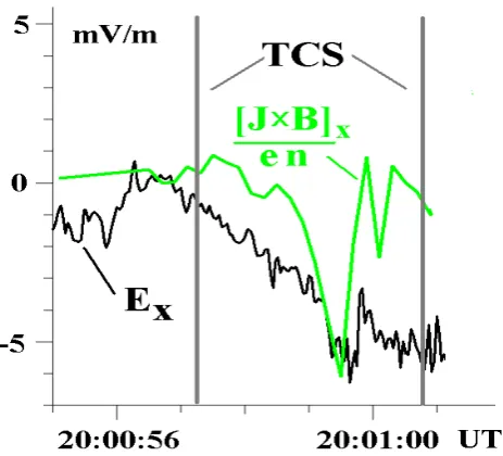
Fig. 6. Comparison of the electric field EFig. 6. Comparison of the electric fieldx with the Hall term into TCS (see text for details). Exwith the Hall term into
TCS (see text for details).
field-aligned currents and other kinetic and dynamic effects can neutralize the inner electric field (cf. Genot et al., 2004), especially in the case of a dense inner boundary layer. In this dense layer any necessary “active” surface charge can be easily provided by the field-aligned electrons (with electron density rising by tenths cm−3), including that one support-ing the non-GDCF positiveEx, which might serve to remove
plasma in front of the moving MP (cf. Fig. 1).
4 Small-scale electrodynamics
Another process, with a possible “active” role of the surface charge, is providing the MP current from the Hall current at a TCS of finite-gyroradius scale (required by the magnetic field rotation). The Hall effect results from an electron cur-rent due to the cross-field drift of electrons, when a substan-tial part of the flow-carrying ions move in the direction of electric field (see e.g. Sibeck et al., 1999 and Figs. 2 and 4–6 in [A]). An important issue is that the Hall effect and related thin electron currents are a characteristic feature for any cur-rent of ion finite-gyroradius scale independent of reconnec-tion, which certainly should enlarge the mass and momentum transport, but it is not the necessary TCS feature.
Mozer et al. (2003) and Vaivads et al. (2004) provide com-prehensive examples primarily for Hall dynamics in TCS from Polar and Cluster data. But they concentrated mostly on a comparison of the data with a limited stationary recon-nection model with X-line, requiring a singular “diffusion region”. This “diffusion region” should be very limited in space, including its length along MP. In contrast, the ion Hall effect in the thin current sheet should exist all along the sheet, unless the sheet width is comparable with ion gyroradius. In
this case the frozen-in condition for ions is violated due to the small current scale, it could be also described in terms of an effective viscosity (see e.g. Stasiewicz, 1994). Belmont and Rezeau, (2001) show similar effects of Alfven waves on the magnetic flux erosion and use the term ’micro-reconnection’ in contrast to a stationary laminar reconnection with the X-line configuration (see Sibeck et al., 1999).
Thus we outline the Hall dynamics in the TCS per se, while transient (and multiple) X-, Y-, O-lines etc. might be incorporated into a particular scenario of the current sheet evolution (see e.g. Syrovatskii, 1971; Sibeck et al., 1999; Silin and Buechner, 2003; Savin et al., 2005a). To do a qual-itative test particularly for Hall dynamics in the TCS in our case, we calculate the Hall term in the generalized Ohm law (see e.g. Sibeck et al., 1999) using the data from Cluster 1 and inferred TCS geometry and velocity from 4 Clusters and compare its X-component with that of electric field:
[j×B]x/en= −(BzdBz/dx+BydBy/dx)/µ0en (1) wherej is the current density,nis the plasma density from spacecraft potential with 5 Hz sampling, normalized through the WHISPER density data, e is the electron charge. We have neglected all other gradients besides that in X-direction, as the normalNE is close to the X-axis, and the maximum
variance procedure gives very different eigen values (i.e. the TCS can be regarded as a locally flat structure, cf. Dunlop et al., 2005, [A]). We also substitutedx∼Vxdt, where the MP
speed componentVx∼30 km both fromVMP andVCTA(see [A]). At the distance between spacecraft of ∼600 km with such MP speed one cannot get quantitative estimates of other terms in the Ohm equation having maximum resolution of the particle instruments of 4 s (cf. Sibeck et al., 1999; Vaivads et al., 2004; Mozer et al., 2003a). The result of comparison of the main electric component and the Hall term inside TCS is depicted in Fig. 6: the green line shows the Hall-term X-projection, the black oneEx; in the middle of the TCS one
can see that the spike in[j×B]x/en∼Ex(now in the
space-craft frame, unlike Fig. 4), while at its borders the electric field matches the outer values, i.e. the boundary conditions, required for driving the respective frozen-in plasma jets out-side the TCS. Thus with the available time resolution we can infer rather space than surface electron charge into the TCS, which serves both to support the necessary separating cur-rent via the Hall effect, and to fit the surrounding flows and fields, including the MP motion. Remembering that the vari-ability of magnetic disturbances near the TCS on different spacecraft (Fig. 9 in [A]) introduces extra uncertainty in cal-culating of the Hall-term; we also take into account the geo-metrical and single-spacecraft limitations in our calculations of the Hall term. Then we can infer fairly satisfactory fitting of the data to the Hall physics in the center of the TCS. We have checked, that theEx almost does not depend on
trans-formation in frames, moving at speedsVMP orVCTA(asEx
Dunlop et al. (2005) use magnetic data from all spacecraft to calculate the current by the curlometer technique and pro-pose that the magnetic stress[j×B]at the MP can acceler-ate the jet just inside the MP downward, i.e. the stress could play an “active” primary role. Our comment on that is that their calculation is made on a∼600 km scale, which is much larger than that of the TCS width of∼90 km. On the con-trary, we propose that this should be a second-order effect, remembering the large ionβ, which is especially high in the “plasma ball” and advocate the decisive role of the electric forces and surface charges. However, we realize that this should be confirmed through an appropriate modeling in fu-ture.
The potential difference for driving electron current along field lines can be provided by inertial (polarization) drift of the incident MSH ions in the non-uniform electric field of the surface charge, seen in the frame of bulk motion by the MSH plasma (see Fig. 1, 5, cf. Genot et al., 2004; Savin et al., 2005b). For a non-uniform electric field the zero ap-proximation of the electric field cross-field drift with velocity Vd(0)=[E×B](EandB– electric and magnetic field vectors) is broken and one should take into account the first-order in-ertial drift (Golant et al., 1977):
Vd(1) =Ze/(MωH2)dE/dt (2) whereM,ωH,Zeare respectively the mass, cyclotron
fre-quency and charge of the particles. This approximation is valid only for space scales larger than the ion gyroradius and frequencies smaller than the ion gyrofrequency. In the opposite limit for small scales, the electric field should ac-celerate the ions directly, providing the Hall electron cur-rent in the transverse direction. Regarding the disturbances at 20:00:30–20:00:50 UT in Fig. 4, a characteristic veloc-ityVMP (∼30 km/s, ignoring its departure from X-axis) and |B|∼50 nT (see Fig. 1 [A] and 1), one can get the appropriate scaling for different ion energies; the proton gyrofrequency being ∼0.75 Hz. As an example we take the Ex0 rise at 20:00:24–26:00 UT (see Fig. 4), then (2) givesVd(1)∼3 km/s; the respective maximum ion shift from electrons in X di-rection due to inertial drift Li∼5 km (i.e. of the order of
few electron inertial lengths or that of gyroradii); the in-ferred structure scaledp∼50 km that corresponds to
gyro-radius of∼500 eV protons, so that the drift approximation is valid only for the protons with smaller energy. The pro-tons with higher energies should loose∼100 eV in the sun-ward directed electric-field pulse of finite-gyroradius scale. In another spike at 20:00:15 UT with the inferred width of ∼60 km and total potential change of the order of 180 V, the inertial drift effects are negligible as the spike switches on and off faster than proton gyroperiod. Protons with energy >900 eV (gyroradius∼60 km) loose the total potential en-ergy; that of∼200 eV (and less) with gyroradius of the order of a half of the pulse width do not change their energies as the loss at the leading front is comparable with the gain at
the trailing one. From 200 to 900 eV the energy loss rises to 180 eV, so that the respective velocity dispersion should re-sult in a space charge, presumably neutralized by the parallel electron currents (cf. Genot et al., 2004). This inferred inter-action with the small-scale electric fields is similar to that of the Hall dynamics of the TCS, discussed in section “Plasma inflow and momentum balance”. While some electric bursts, to which we attribute potentials∼100 V, could be temporary, the high correlation of theEx-signals (especially∼0.93 on
Clusters 2–4, separations of which in the normal direction is comparable with the TCS width, see [A]) with the definite lags, suggests their spatial nature in the majority of cases.
During the strong sunward electric field from 19:55 to 20:00 UT (see Fig. 7), the higher-energy protons meet sev-eral positiveE0x-pulses, thus loosing several hundreds eV. As we have seen (Fig. 2), the ions with energy>300 eV carry main the flow near MP, so namely those ions are subjected to decelerating by the spikes of the normal electric field. This interaction could also account for the density rises of the higher-energy ions (due to piling up by the electric struc-tures), correlating with the Ex-disturbances, in Fig. 1 after
the disturbance in electric field∼at 19:50 UT.
The velocity of inertial drift changes sign at positive and negativedEx/dt(see Eq. 2), being of the order of few km/s
388 S. Savin et al.: Experimental study of nonlinear interaction of plasma flow 2
Fig. 7. Cluster-1, February 13, 2001. (a): WHISPER electric field spectrogram (see [A]) with color-coded intensity (scale at the right side); (b): electric field E`x in the MSH frame are superimposed (see Fig. 5); (c): index of variation as deduced from the DWP correlator measurements for the pre-set energy (i.e. 40eV to 100eV), which quantifies the variance in the electron counting process that the DWP correlator performs. The values are normalized to the electron count rate and a value of unity indicates the electrons are random Poisson distributed; (d) an estimate of ion effective collision frequency, deduced from correlated fluctuations of ion density and E`x for the band 0.1-2.5 Hz, averaged over 50 s.
Fig. 7. Cluster-1, 13 February 2001. (a) WHISPER electric field spectrogram (see [A]) with color-coded intensity (scale at the right side); (b)
electric fieldE0xin the MSH frame are superimposed (see Fig. 5); (c) index of variation as deduced from the DWP correlator measurements
for the pre-set energy (i.e. 40 eV to 100 eV), which quantifies the variance in the electron counting process that the DWP correlator performs. The values are normalized to the electron count rate and a value of unity indicates the electrons are random Poisson distributed; (d) an
estimate of ion effective collision frequency, deduced from correlated fluctuations of ion density andEx0 for the band 0.1–2.5 Hz, averaged
over 50 s.
an index of variation as deduced from the Data Wave Pro-cessor (DWP, see Woolliscroft et al., 1997) correlator mea-surements for the pre-set energy 40 eV to 100 eV. The index of variation quantifies the variance in the electron counting process; the values are normalized to the estimated count rate and a value of unity indicates the electrons are random
electron parameter, which provides information about local processes in the high-frequency range at electron-scales. In any case, the index displays non-equilibrium state of elec-trons. In Fig. 7c we put a threshold of +/−0.03 for the index of variations, marked by horizontal lines, and in∼73% cases at the time scale of spacecraft spin one can see appearance of wave spikes on the top panel in the band of the electron plasma frequency (20–60 kHz); the reverse cross-correlation is∼53%. A narrowness of the electron disturbances follows from the correlator sample group interval of 732 microsec-onds, which corresponds to 20 m (of the order of the Debye length) in the case of scaling by the MP speed of∼30 km/s, and to 200 m for that of the MP jet (see Fig. 1 [A]). The scales of electron disturbances look to be underestimated on the background of electron inertial length and gyroradius be-ing of few km, but certainly these scales are much shorter than the characteristic ion ones. The similarity in behavior of the high-frequency waves in electric field and the electron in-dex of variation is suggestive for the local origin of the waves and/or their strong interaction with the electrons.
To get an order-of-magnitude estimate for the effective collision frequency (νef)of the ions with the electric
fluc-tuations, we calculate in 10 s intervals and average over 50 s the value of the product of the plasma density (δN) and electric fluctuations in the MSH frame (δEx0) in frequency band 0.1–2.5 Hz, using spacecraft potential with 5 Hz sam-pling as a proxy for the density measurement after its re-calibration by the WHISPER plasma density data. Figure 7d demonstrates that further averaging will not change qualita-tively the pattern: in the region of the inferred interactions the electric field bursts anti-correlate with those of the density, presumably suggesting effective collisions. We have done re-calculation of the averagedδN δE0xinto the effective fre-quency scale similar to Panov et al. (2005). To that purpose, we consider a reduced equation of ion motion in the MSH flow frame and equalize the ion momentum change due to fluctuations by the averaged nonlinear term:
N MdVx/dt≈N MViTνef ≈e
δN δEx0
We find that νef ≈e
δN δEx0/N MViT, (3)
whereM, ViT – proton mass and thermal velocity.
TakingViT as a proxy for the characteristic velocity poses
its maximum value, that gives minimal estimate for the νef ∼2 radian/s in the interaction region in the middle of
Fig. 7d. Thisνef is comparable with the proton
gyrofre-quency (∼0.75 Hz), that infers Hall dynamics in this region, similar to that of the thin MP.νef becomes smaller if one
takes higher frequency limit for filteringδN andδEx0 before calculating (3), but qualitatively the latter suggestion holds.
So, our considerations suggest that in front of MP the sun-ward electric field in the MSH frame: (i) by its DC compo-nent rotates the magnetic field and accelerates the flow
down-stream along the MP; (ii) by its spikes and gradients deceler-ates the higher-energy ions and produce space charges, most probably neutralized by parallel electron flows. Thus, we propose that the smaller-scale electric fields provide a kind of effective collision process for decreasing the average normal flows in the MP vicinity. Equalizing of the parallel and per-pendicular ion temperatures in the zones of intensive electric fluctuations (Fig. 1 [A]) along with the temperature rise in front of MP, conforms to the hypothesis of effective collision operations. Another consequence of the effective collisions should be the heating of O+ from the outer magnetosphere, where its larger gyroradius should provide the more effective interaction with the short-scale electric bursts, compared to protons. In the presence of a surface charge O+ should be accelerated while moving in the direction of the DC electric field outward; we will discuss those points in details in a fu-ture paper.
5 Discussion and conclusions
The Hall effect at such thin charged layers, as the TCS dis-cussed above, separating different plasmas, can serve to sup-port the transverse current between the plasmas selfconsis-tently (i.e. without any “anomalous” resistivity or a “diffu-sion region”). It does not necessarily imply macro reconnec-tion with parallel electric field, while reconnecreconnec-tion should in-clude the ion-scale layers. In other words, a charged TCS just because of its ion-gyroradius width becomes partially trans-parent for the larger-energy ions and respective magnetic flux without any extra change of the field topology (which could be superimposed or not). Transport of momentum across the layers is also provided by ions with larger gyroradius without any magnetic field annihilation. The momentum transfer has been discussed by Stasiewicz (1994) in terms of gyro-viscosity, which in the case of anti-parallel magnetic fields predicts a forcing of the boundary Earthward without a macro-reconnection. The ratio of the normal to MP gyro-viscous stress to Maxwell stresses is∼βρu/2d, whereρuis
directional gyroradius andd– the MP width. Over the cusp and especially at the boundary of “plasma balls” bothβ and ρuare rising due to the magnetic field minimum and due to
the acceleration of the flow around MP towards the tail; thus, the MP inward motion due to this effect should have a max-imum at the sunward edge of the cusp for the IMF Bz<0
in our case (while Cluster entered the cusp at its tailward edge). In spite of sampling of the MP outside the maximum gyro-viscosity effect, Fig. 2 demonstrates clear momentum transfer across the MP, especially in its component parallel to MP.
390 S. Savin et al.: Experimental study of nonlinear interaction of plasma flow 2 should provide a similar measurement pattern, as supposed,
but never clearly demonstrated, for the “diffusion region” of macro reconnection. So, we are skeptical about recent “discoveries” of the “diffusion regions” (see e.g. Mozer et al., 2003a; Vaivads et al., 2004; and references therein): the electron scales are mandatory for the localized “diffusion re-gion”, but their presence all along a thin MP does not nec-essarily imply the boundary topology change and release of magnetic energy, stored in the deformed magnetic field (i.e. a macro reconnection). Mozer et al. (2003) concluded that “significant conversion of electromagnetic energy can occur inside the magnetopause in the absence of an electron dif-fusion region, parallel electric fields, or the electrons being decoupled from the magnetic field. . . . these properties are consequences of the Hall MHD and guide electric and mag-netic fields in the absence of any additional non-MHD pro-cesses”. In this paper we are outlining the effects of electric fields at the finite-gyroradius scales, which should accom-pany any Hall-MHD structures (with scales of the order of the ion gyroradius of, at least, the higher-energy ions, carry-ing nevertheless the substantial part of the plasma momen-tum). We plan to check our suggestion of the appearance of electrons scaled as a consequence of the inertial drift by respective modeling in a future paper.
In [A] we demonstrate the existence in the MP vicinity of at least three ion sub-populations from different sources, in-cluding mantle-like ions, which are usually attributed to the remote reconnection on dayside (see Fig. 5 and related dis-cussions above). Outlining here the operation of the local finite-gyroradius penetration and MP charging, we would be unable to define a mutual importance of the local and remote mechanisms for plasma transport and jet formation, basing only on the local measurements. Gas dynamic modeling with realistic MP shape, obtained from the pressure balance, promises to shed a light on that in a future paper. A brief inspection of the electron data (see Fig. 3 in [A] and related discussions) did not improve much the situation: the counter-streaming heated and core populations can be accounted for the dayside reconnection, while the cold anti-parallel elec-trons (i.e. flowing from the tail towards the dayside along the MSH field lines near MP) are detected throughout MSH, starting from a postshock region at 16:50 UT (not shown, cf. anti-parallel flows at 50–77 eV in Fig. 3 from [A]). Because of that these electrons hardly can be used in our case as the reconnection tracers. As for the bi-directional electrons out-side MP, Savin et al. (2004b) accounted for their heating near MP by positioning spacecraft inside the distributed region of electron acceleration by presumably waves in the low-hybrid band. Dominating of the parallel electrons is a hint for a superimposed distant source, first of all of the dayside re-connection site. Appearance of the quasi-perpendicular elec-trons at the higher energies (cf. Fig. 3 in [A]) can be at-tributed to the fan instability of the parallel electron flows (see Savin et al., 1997, 1998 and references therein). Tak-ing 10 periods of the low hybrid frequency (10–20 Hz) as
a proxy for the time of fan instability development, for the velocity of 100 eV electrons one would get a distance to a source of∼0.5–1RE, that corresponds rather to ion
time-of-flight estimates (that gives the spread of the finite-gyroradius penetration of 2–3RE, see Fig. 3 and related discussions),
than to the distance from the dayside reconnection site (cf. Fig. 5b). The time-of-flight of the bursty protons, leaking from the outer cusp presumably via finite-gyroradius effect, can be utilized for remote sounding of the MP width along field lines.
Finally, the study of nonlinear dynamics of the plasma flow interaction with the geomagnetic trap highlights a fun-damental role of the finite-gyroradius effects, surface charges and related accelerated plasma jets. In the MP boundary lay-ers the accelerated jets provide a flow balance via the rotation of magnetic field (relative to GDCF model predictions) and via the “active” electric field (superimposed on that predicted by GDCF model), most probably supported at the moving and indented MP by parallel electron currents. The com-plicated MP shape suggests its systematic velocity departure from the local normal towards the average one. The electric fields in the MSH frame both accelerate the MSH plasma along MP downstream and provide effective collisions via deceleration of the higher-energy MSH ions in the process of interaction with the finite-gyroradius electric bursts. These interactions should reduce the MSH normal flows just in front of MP and create charge separation, which is suggested to be neutralized by parallel electron currents. The effec-tive collisions, with frequencies of the order of the ion cy-clotron one as estimated from the nonlinear transport term in (3), should result in the ion heating (cf. Fig. 1 in [A]) and in the Hall ion dynamics, i.e. acquisition of the larger-scale transverse electric potentials (due to quasi-DC electric field in the MSH frame) by the higher energy ions. While our order of magnitude calculations of the collision frequency do not provide quantitative estimates for the ion dynamics, yet they outline the valuable role of the nonlinear correla-tions (i.e. the finite average value ofδN δEx0), which should be taken into account in the problem treatment and model-ing. Based on the above considerations, we are preparing the separate paper on comparison of this data with nonlinear turbulence modeling in the presence of the DC electric field. These effective collisions in the extended turbulent zones (cf. Savin et al., 1998, 2002, 2004b) are a promising alternative in place of the usual parallel electric fields invoked in the macro-reconnection scenarios.
Acknowledgements. Work was partially supported by
INTAS-03-50-4872, INTAS 05-1000008-8050, RFFS 06-02-17256,
04-02-17371 and 03-02-16967, ISSI (Team 81), KBN 8T12 E 016 28, ECRT Network HPRN-CT-2001-0314, and Science School 1739 2003 2.
Edited by: N. Watkins
![Fig. 2. Cluster-1, February 13, 2001. (a): ion flux ‘nViyity (V) in Fig. 8 from [A]. Taking the estimate for width ofblack – partial ion flux for > 300 eV, red – for > 1keV ions; (b) the same for ‘nVix’; (c) the same for ‘nV’; (d): ion density n (blue), p](https://thumb-us.123doks.com/thumbv2/123dok_us/58754.1506297/4.595.46.293.61.532/cluster-february-nviyity-taking-estimate-ofblack-partial-density.webp)
![Fig. 1 [A]). This suggests an “active” role for the normalelectric field in the MP vicinity in the regulation of theplasma flow balance](https://thumb-us.123doks.com/thumbv2/123dok_us/58754.1506297/7.595.311.545.64.452/suggests-active-normalelectric-eld-vicinity-regulation-theplasma-balance.webp)