GSJ© 2018
GSJ: Volume 6, Issue 6, June 2018, Online: ISSN 2320-9186
www.globalscientificjournal.com
EFFECTIVINESS OF FACTS DEVICES FOR THE CONTROL OF POWER SYSTEM
TRANSIENT STABILITY USING DIFFERENT INTELLINGENT TECHNIQUES.
Alfred, B. Baams,
Department of Electri cal/Electronics Engineering Modibbo Adama University of Technology, Yola Ada
mawa State, Nigeria
Email:
Dr. J. Usman, Department of Electrical /Electronics Engineering, University of Maiduguri,
Nigeria. Email:
Simon Samuel
Department of Electri cal/Electronics Engineering Modibbo Adama University of Technology, Yola Ada
mawa State, Nigeria
Email:
Ishiwu I. Jude
Department of Electri cal/Electronics Engineering Modibbo Adama University of Technology, Yola Ada
mawa State, Nigeria
Email:
Abstrac: This paper is aimed towards the benefits of utilizing flexible Alternating current transmission system (FACTS) devices us-ing different intelligent techniques with the purpose of improvus-ing the operation of an electrical power system. Voltage instability is considered as a main threat to stability, security and reliability in the modern power systems. The application of FACTS controllers has been for the purpose of maximizing the lines conductivity given the restrictions involved, including the issue of stability. The main causes of voltage instability and solutions have been reviewed [29]. Hence, effectiveness of the proposed techniques employed is ro-bust to different operating conditions and disturbances. Performance comparison of different FACTS devices has been discussed. Sem-iconductor technology development and utility experience have been reviewed and summarized. The used and installation of FACTS devices on the power transmission lines has been discussed. This survey article will be very much useful to the researchers for finding out the relevant references in the field of voltage stability enhancement by using FACTS devices in power transmission system.
Keywords: FACTS Devices, Intelligent Techniques, Reliability, Security, Stability,
1. INTRODUCTION
The rapid increasing of power demand and expansion of transmission network day by day, it affects the complexity to maintain the stability of electricity [4]. Nowadays energy systems are highly complex and widespread that operates much closer to their breakdown limits, due to economic, environmental, political and technical factors (e.g power losses and fluctuations). Despite the fact that the volume of power transmission and power con-sumption have been increasing in non-uniform use of facilities, unwanted pathways or rings and as well as transmission corri-dors, has affected or limited the growth in power transmission [14]. FACTS technology is considered as important devices to make full use of available transmission facilities in emergencies with no security problem in the system, interesting feature of these facilities is direct control of the power passing through transmission lines by changing parameters of grid structure via
high-gain control systems based on fast switching [1]. Unsuitable location of FACTS devices, high reactive power consumption at heavy loads, occurrence of contingencies and reverse operation of ON load tap-changer (OLTC), also the voltage sources are far from load centers and improper coordination between multiple FACTS controllers constitute instability of power systems [9].
generally power electronics based devices which build-up of thy-ristor valve and voltage source converter (VSC) [21]. Under the FACTS devices it has three stages such as; shunt series, shunt and series devices. The thyristor valve consist of SVC, TCSC, DFC and HVDC B2B and voltage source converter (VSC) are; STAT-COM, SSSC, UPFC/IPFC and HVDC B2B. These devices are wisely coordinated to dynamically adjust the Network configura-tion to enhance steady-state performance as well as dynamic sta-bility [9]. The FACTS controller can provide variable turn and/or series compensation by coordinating with one another. The insuf-ficient of electric energy can be overcome or minimized by using the technology of FACTS controller [19]. Stability is the ability of the system to develop restoring forces equal to or more than the disturbing forces and remain stable when subjected to the disturbance [3]. The applications of the FACTS controllers in power system has really help in the improvement of power transmission system as well as provide operating flexibility to the power system [20]. However, these FACTS technology helps the industries to better utilize existing generation and transmission reserves with the good power system performance [1]. The coor-dination of FACTS technology such as gate turn-off thyristor-switching converters (GTO), thyristor controlled series capacitor (TCSC), thyristor controlled phase shifter (TCPS), static syn-chronous compensator (STATCOM), static synsyn-chronous series compensator (SSSC), unified power flow controller (UPFC) and the interline power flow controller (IPFC), are used for the en-hancement of transmission network capability. They are inter-faced to power system at appropriate location of the transmission lines, in series, shunt or in combination of series and shunt [12].
2. FACTS DEVICES
2.1 Thyristor-Controlled Series Capacitor
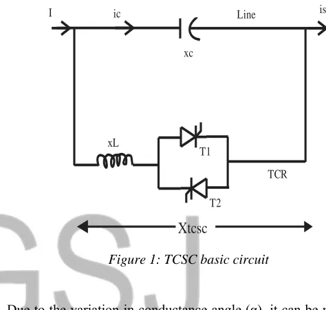
Thyristor-controlled series capacitor (TCSC) is an im-portant device in the family of FACTS devices, which uses thy-ristor-controlled reactor (TCR) in parallel with capacitor seg-ments of series capacitor bank [4]. TCSC is slightly different from SVC. TCSC address specific dynamic problems in trans-mission system, by increases the damping when large electrical systems are interconnected and as well as overcome the problem of sub-synchronous resonance (SSR), a phenomenon that in-volves an interaction between large thermal generating units and series compensated transmission system [18]. TCSC is directly connected to the AC transmission line, whose capacity of power transmission has to improve. It is connected by series connection with main line. Static voltage stability margin enhancement using TCSC says the combination of TCR and capacitor allows the capacitive reactance to be smoothly controlled [14]. The con-trolled impedance can be programmed in a way that it can react in a distinct method in emergencies and increases power system security [15]. TCSC in transmission system is adopted in order to
balance natural load in parallel transmission lines for maximum transmission capacity. Transmission active power depends on transmission line reactance [17].
(1)
The impedance of grid series is adjustable through thyristor con-trollers that changed the power transmission. The basic circuit of TCSC [11] is shown in figure 1.
Figure 1: TCSC basic circuit
Due to the variation in conductance angle (α), it can be modeled as a fast switch inline with the reactance of power system. The modeled TCSC is shown in fig.2 below;
Figure 2: Modeled TCSC
The increase or decrease in thyristors’ conductance period and consequently, the current passing through TCR is controlled by compensation degree of series [16]. The difference in electric angle between the positive voltage passing through zero and the
1 2sin( 1 2) / X
PV V
I ic Line is
xc
xL
TCR T1
T2
Xtcsc
GSJ© 2018
current passing through zero is called the firing angle (α) of TCR. α˂90˚ no control over inductive current. α˃180˚ is not possible for thyristors because of limitation in thyristors’ symmetrical firing [5]. TCSC reactance is obtained as
XTCSC = (XCXL)/ (Xc/n) [2(π-α) +sin2α]-XL (2)
Where, α, XC and XL denote firing angle of thyristor, capacitor
reactance. TCSC is connected in series in the transmission line with relation to reactance of the transmission line.
Χij = ΧLine + ΧTCSC (3)
For TCSC to have a better modeling in optimization, we have
ΧTCSC =RTCSC * ΧLine (4)
Where R = compensation factor of TCSC it varies based upon where exactly is connected on transmission line ranging between -0.7 and 0.2 schematic view of TCSC [14] is shown in figure 2.
2.2 Unified Power Flow Controller
The Unified Power Flow Controller (UPFC), act as a shunt compensating and a phase shifting device because it is a combination of a static compensator and series compensation. It has the best effect on efficient steady state transmission [12]. Also, it has ability to adjust the three control parameters, i.e the bus voltage, transmission line reactance and phase angle between two buses, either simultaneously or independently [23]. UPFC has two voltage source inverters and a common capacitor be-tween them, and they are connected to the grid in series/parallel by two transformers. This technology is setting effect on steady state, dynamic and transient stabilities [11]. The UPFC is the most versatile and complex power electronic equipment that has emerged for the control and optimization of power flow in elec-trical power transmission system [8]. UPFC provide multifunc-tional flexibility required to solves many of the problems facing the power industry [10]. The UPFC circuit is shown in figure 3.
Figure 3: UPFC Structure
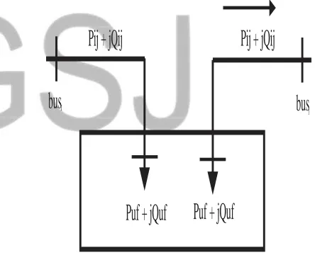
The UPFC is modeled in two ways, coupled and decoupled mod-el. Coupled model is more complicated, is corrected here by Ja-cobian matrix whereas, decoupled model load dispersion algo-rithms without need to correction or simplification of Jacobian matrix was used [7]. The latter model has adopted, see figure 4.
Figure 4: Decoupled model of UPFC
2.3 Static Synchronous Series Compensator
The Static Synchronous Series Compensator (SSSC) is a series voltage source, which work the way as the STATCOM, but this device is more complicated because of the platform mount-ing and the protection [5]. A thyristor protection is necessary due to the over load capacity of the semiconductors especially when IGBTs are used [8]. SSSC is connected to a transmission line by series connection through a transformer. It is an energy source to provide a continuous voltage through a condenser and compen-sate the losses of the VSC. This device is then called dynamic
Transmission Line
Series Transformer
Shunt Transformer
is
v
1I
Inverter 1
Inverter 2
Pij + jQij
bus
Ibus
jPuf + jQuf
Puf + jQuf
voltage restorer (DVR), which is used to keep the voltage level constant e.g factory in feed [9]. Hence, with the charging mecha-nism or battery on the DC side, the device can work as UPS (un-interruptible power supply). SSSC, with reactive power compen-sation only the voltage is controllable, because the voltage vector forms 90˚(degrees) with the line intensity [6]. This means that the SSSC can be uniformly controlled in any value, in the VSC working slot, as shown in figure 5.
Figure 5: Static Synchronous Series Compensator (SSSC).
2.4 Static VAR Compensator
The term ‘static’ refers to the fact that the Static VAR Compensator (SVC) has no moving parts other than circuit breakers, which do not move under normal SVC operation. It is connected with the transmission line in parallel connection, which works as a generator as well as a load for the transmission line; the primary purpose is quick control of voltage at its weak point of the network [8]. A rapid operating static VAR compen-sator (SVC) can provide the reactive power required to control dynamic voltage oscillations under various system conditions, and thereby improve the power system transmission and distribu-tion stability [20]. The SVC increase transfer capability and re-duce losses, also smooth voltage profile is maintained under dif-ferent network conditions, when installed at one or more points in the network [11]. The SVC is an automatic impedance matching device, designed to bring the system closer to unity power factor. If the power system’s reactive load is capacitive, the SVC will use reactors to consume VARs from the system, lowering the system voltage under inductive conditions, the capacitor banks are automatically switched in. Thus providing a high system volt-age, SVC consists of a TCR (reactive impedance in XL with a
two-way valve-thyristor) parallel with capacitor bank XC and it
adjusts the voltage of connecting point to the grid as a parallel varying reactance by absorbing or producing reactive power, it is mostly applied to provide reactive power very fast and to support
voltage by controlling firing angle of thyristor [10]. Circuit dia-gram is shown in figure 6.
Figure 6: Representation of FC-TCR (SVC) Circuit.
It is connected through a coupling transformer with the main AC transmission line whose voltage has to be regulated. SVC is made by the combination of controllable, by controlling the firing angle of thyristor. Controllable of TCR reactance, XV is derived [7] as
XV=
π
/
(2π
-2α
+sin2α
) (5)α
= firing angle of the thyristorEffective susceptance B in TCR is obtained as
B = (XV+XC)/(XVXC) (6)
2.5 Static Synchronous Compensator:
Static Synchronous Compensator (STATCOM) is built with thyristors, with turn-off capability like GTO or with more and more IGBTs. A STATCOM is a regulating device used on grid network. Static synchronous compensator (STATCOM) acts as a source of reactive power to transmission network which was based on electronics voltage source converter. It provides active AC power if connected to a source of power [21]. A poor power factor of an electricity network is supported by installing STAT-COM and often poor voltage regulation compensator (STAT-COM) has characteristics similar to the synchronous condenser, but as an electronic [7]. Static synchronous device has no inertia and is superior to the synchronous condenser in several ways, such as better dynamics, a lower investment cost, lower operating and maintenance costs [18]. Advantage of a STATCOM is that, the reactive power provision is independent from the actual volt-age on the connection point. The combination of active and reac-tive power improves the performance for power quality and bal-anced network operation. The most common use is for voltage stability, and as well provides better damping characteristics than
Coupling Transformer Transmission Line
Static VAR Compersator
TSC
TCR
L
AC
v
1
i
1
DC
GSJ© 2018
the SVC as it is able to transiently exchange active power with the system [2].
Figure.7: STATCOM Structure
Figure 8: Voltage/Current characteristics
2.6. Comparing TCSC and UPFC.
In terms of their influence on system reliability, compar-ison is made to confirm the difference of both TCSC and UPFC. TCSC has the ability to control active power in power system [11]. The continuous varying capacitor whose impedance range in 0 ≤ XG ≤ ZC maximum is by the TCSC, which controllable series capacitor impedance can reduce a part of inductive reac-tance in transmission line and decrease total impedance of trans-mission line and consequently, increase transmissible power [13]. Increased in transmissible power is a fixed percentage of trans-mitted power by uncompensated line in a given transmission an-gle. This associated with the fact that TCSC is series impedance and the compensated voltage by TCSC is dependent on transmis-sion line current, whereas UPFC is a voltage source and compen-sated voltage by UPFC is not dependent on line current, it is de-pendent on maximum series voltage by UPFC. Assumed TCSC is connected to the transmission line L1 in series. Compensation
angle is in such a way that total inductive reactance of line L1
equals half of inductive reactance L2, moreover, it is assumed
that reliability of TCSC and UPFC is 100%, by reducing
trans-mission angle and using TCSC, transmitted power from L1 and L2 are 1.5P and 0.75P [14] figure. 7 TCSC vs UPFC (reliability
related to two situation).
2.7 Integral Power Flow Controller
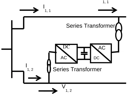
Integral Power Flow Controller (IPFC) controlled the power flows of two lines starting in one substation. The IPFC consists of two series VSCs whose DC capacitors are coupled, which permits active power to circulate between VSCs. To opti-mize the network utilization two lines can be simultaneously con-trolled [1]. In the general conceptual frame work of the converti-ble static compensator (CSC), two multi-converters FACTS-devices, such as, integral power flow controller (IPFC) and gen-eralized unified power flow controller (GUPFC) are among many possible configurations, with the target to control power flows of multi-lines or sub network, rather than controlling the power flow of a single line, for instance, the use of DFC or UPFC [17]. Two or more series converters are combined by integral power flow controller (IPFC), whereas only one shunt converter is combined by generalized unified power flow controller (GUPFC) [22]. Therefore, the current NYPA’s CSC installation is a two convert-er in one and can opconvert-erate as an IPFC. The CSC is the latest FACTS devices which were installed recently as a pilot by the New York Power Authority (NYPA), mainly to increase power transfer capability and maximize the use of the existing transmis-sion Network [4]. Hence, for IPFC two series VSCs connected to each other at the DC bus, one of them (assumed as the master VSC) can control both line active and reactive power and the other one (assumed as the slave VSC) can only regulate power line, by supporting sufficient active power to the master VSC through the DC tie [2]
Figure 9. Configuration of an IPFC
2.8 Distributed Power Flow Controller
Capacitive Inductive Ii
s AC
DC
Battery
I
s
AC
A
ACDC
DC
AC
Series Transformer Series Transformer
V
1, 1
V
1, 2
I
1, 1
I
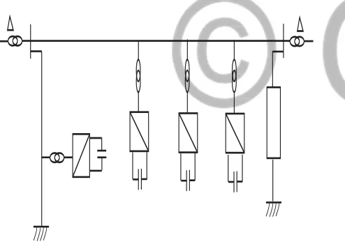
Distributed Power Flow Controller (DPFC) is a hy-brid device between a phase shifting transformer (PST) and switched series compensation. Due to the high voltage, high power (multi-hundred MVA) and high cost, the device is not widespread. The DPFC has the following major components such as; single turn transformer, single phase voltage source inverter, filter and controlling module, self-production module [18]. The introduction of the DPFC was the proposed approach as an alter-native for realizing the functionality of FACTS-devices. The DPFC designed proposal was derived from UPFC. So, the in-crease reliability of the system was due to the absent of a com-mon DC link between the converters. The transmission lines at a third harmonic frequency resulted to active power exchange be-tween series and shunt converter [7]. The DPFC device is rated about 10KVA, with the devices connected on the transmission line. Here, the steady power flow is achieved by increasing or decreasing the impedance of the line [15]. The reactance of the DPFC is exchanged based on the AV1. The port network formed by AB to meet the flux and current of inductance is equivalent to the inductance and transformer which can also be controlled by the negative inductance. AV1 is proportional to L with the large number of modules working together, gives better effect on the overall power flow in the line [4].
Figure 10. Distributed power flow controller (DPFC)
3. STABILITY IN POWER SYSTEM NETWORK
Due to different devices and instruments used it is complex in nature to identify the stabilities and getting improve-ment on them. The classes of stabilities are many, depends on various factors of the power transmission system. Such as; volt-age stability, frequency stability and rotor angle stability [9]. Voltage stability: the power system stability is the ability of the system to maintain steady current/voltage at all the transmission lines after encountered disturbance [11]. Here, the load demand and supply from the power system are able to maintain a balance. There are various voltage instabilities such as; voltage
fluctua-tion, voltage losses, voltage drops, voltage surge, etc. this can be minimized by maintaining the condition of generators and other devices in good manner. Also good operating condition and de-sign of machineries, equipments and skilled operated periodically maintenance. Voltage stability has two branches; large-interruption voltage stability and small-large-interruption voltage sta-bility [20].
3.1 The Large-Interruption Voltage Stability: -
It is the ability of the system to manage steady volt-ages, subsequent large interruption being system faults, loss of generation or circuit exigency [2]. It can be resolved by the sys-tem and load characteristics, and interactions of both continuous and discrete control protections. The small-interruption voltage stability is to maintain steady voltages when subjected to mini-mum perturbations, it is clouted by the characteristics of loads, continuous control and discrete control at a given instant of time [5]. Frequency stability;it is assign to maintain steady frequency due to imbalance between generation and load, with minimum inadvertent loss of load, fluctuations that may conclusion ensue in the form of interrupted frequency swings well-known to trip of generating unit or load [7]. Rotor angle stability; it is the persis-tent in synchronism of synchronous machine of an interconnected power system network subsequently been subjected to an inter-ruption [12]. The instability occurs due to an increasing angular swing of the generators or loss of synchronism with other genera-tors. The loss of synchronism happens by the non-equilibrium state between mechanical torque, electromagnetic torque and speed difference between the generators [3].
4. IMPORTANTS OF USING FACTS CONTROLLERS
A new algorithm was developed by researchers in the previous years for addressing the optimal power system instabil-ity by applying FACTS devices. The SVC and TCSC of FACTS devices are modeled as controllable impedance. Whereas IPFC, SSSC, STATCOM, UPFC are modeled as controllable voltage sources [16]. The demand of electricity is increasing at a speedy rate without any enhancement of power transmission networks [6]. Therefore, deregulation of electricity will create an environ-ment for forces of competition and bargaining [9]. The benefits of utilizing FACTS controllers in power systems are; effective utilization of transmission system assets. The availability and reliability of power transmission system increases, also dynamic and transient grid stability increased as well as reduction of loop flows and better quality of supply for sensitive industries. There has been an increased use of the FACTS devices applications in an electricity market having pool and contractual dispatches [13]
GSJ© 2018
Flexible alternating current transmission system, pro-vide an opportunity to control, stabilize, and elevate power capa-bility in alternating current power system. Transmission and dis-tribution of power energy are regarded as dynamic and growing aspects of engineering. The essential features of FACTS control-lers and their potential to improve system stability is the prime concern for effective and economic operation of the power sys-tem. FACTS devices have established itself as a proven and ma-ture technology. It is one of the most important too for the opera-tional flexibility and controllability in system operator. FACTS technology is not a single powerful technology but it is a set of controllers, each is able to control one or some system parameters in isolation or in combination with other controllers. A properly selected FACTS devices can solve specific limitations of a given line or corridor. FACTS devices helps to better utilize the existing transmission resources, where the utilities are facing the problem of transmission expansion. This all indicates that there is a great potential for its application in future with literature survey it can be analyzed that the capability of FACTS devices power stability is achievable. The application of different intelligent technique of FACTS devices instability of electric energy system can be ad-dress.
6. ACKNOWLEDGMENT
With sincere gratitude to the authors, who in one way or the other contributed to the development of this work. Also, my thanks go to Dr. J. Usman, of Electrical /Electronics Engineering department, University of Maiduguri, Nigeria, for his valuable suggestions and support rendered throughout this research work.
References
[1] Asare, P. (1994). An overview of flexible ac transmission sy ems.st
[2] Banakar Basavaraj, Ronad Basangouda, Jangamshetti Suresh. H. 2012. Transmission Loss Minimization using UPFC. International Journal of Modern Engineering Research (IJMER). 2(5): 3602-3606 ISSN: 2249-6645
[3] Ch. Rambabu, Dr. Y. P. Obulesu, Dr. Ch. Saibabu. 2001. Improvement of Voltage Profile and Reduce Power System Losses by using Multi Type Facts Devices. International Journal of Computer Applications (0975 - 8887). 13(2). [4] Darabian, M., Khorram, B., & Azari, M. (2013). Improvement
of power system transient stability using an intelligent control method, (4), 192–200.
]5] Dash, J. K. (2015). Control strategy for reactive power using fc-tcr by, 2(4), 39–43.
[6] Grids, R., & Litvinov, E. (2016). How Do We Manage the Complexity of the Grid ?, (May), 1–36.
[7] Hesterman, B. (2007). Analysis and modeling of magnetic
coupling, (april).
[8] J. Hossain and H. R. Pota, R. (1987). Power system voltage stability and models. http://doi.org/10.1007/978-981-287-116-9
[9] Kamel MERINI*, F. Z. G. (2003). Improvement of voltage stability in electrical network by using a STATCOM. ]10] Konishi, S., Baba, K., & Daiguji, M. (2000). Var
compensators.
[11] Kumaar, T. A. R. (2012). Power system security enhancement using FACTS devices in a power system network with voltage dependent loads and zip loads, 45(4), 26–39.
[12] L. Gyugyi, "Dynamic Compensation of AC Transmission Lines by Solid-State Syinchronous Voltage Sources", IEEE Transactions on Power Delivery, Vol. 9, No. 2, April, 1994 [13] L. ~Gyugyi, " Unified Power-Flow Control Concept for
Flexible AC Transmission Systems", IEE Proceedings-C, Vol. 139, No. 4, July, 1992
[14] Mohanty, A. K., Barik, A. K. (2001). Power system stability improvement using FACTS devices. international journal of modern engineering research (ijmer), 1(2), 666–672. [15] N. G. Hingorani and L. Gyugyi, Understanding FACTS:
Concepts and Technology of Flexible AC Transmission Systems. New York: IEEE Press, 2000.
]16] Parate, Y. A. (2015). Power system stability improvement using FACTS devices, 3(5), 809–815.
[17] Patel, D. A., Patani, N. P., & Kumar, P. (2013). Analysis of the effect of tap changing transformer on performance of SVC, 3(12), 1–8.
[18] R. M. Mathur and R. S. Basati, Thyristor- Based FACTS Controllers for Electrical Transmission Systems. IEEE Press Series in Power Engineering, 2002.
[19] Sebastian, L., & Rp, S. (2014). Power flow control in a transmission line using unified power flow controller, 4, 36–44.
[20] Singh, B. (2011). Applications of facts controllers in power systems for enhance the power system stability : a state-of-the-art publication of little lion scientific R & D , islamabad pakistan, 6(july).
]21] Singh, B., Verma, K. S., Mishra, P., Maheshwari, R., & Srivastava, U. (2012). Introduction to FACTS controllers : a technological literature survey, 1(9), 193–234.
[22] Sivachandran, P., Hariharan, T., & Pushpavathy, R. (2015). Improvement of power system stability using d-facts controllers : a review, 10(2), 933–939.