EXPERIMENTAL ANALYSIS OF A
VELOCITY FIELD USING VARIABLE
CHIMNEY DIAMETER FOR SOLAR
UPDRAFT TOWER
Neeraj Mehla
Department of Mechanical Engineering, National Institute of Technology, Hamirpur,
Himachal Pradesh-177055.India
Rahul Makade
Department of Mechanical Engineering, National Institute of Technology, Hamirpur,
Himachal Pradesh-177055.India
N.S.Thakur
Centre For Excellence in Energy & Environment National Institute of Technology, Hamirpur,
Himachal Pradesh-177055.India
Abstract
A solar updraft tower consists of an air collector 1.4 m in diameter and 80 cm tall chimney was set up in NIT Hamirpur, Himachal-Pradesh, India.
The objective of the study was to investigate the variation of velocity with essential geometric parameter of the system. The solar updraft tower system consists of three essential elements- collector, chimney height and wind turbine. The output power of a system is depended on the input velocity to the wind turbine. Turbine inlet velocity (V) is the function of five parameter of the solar updraft tower systems such as collector diameter (Dc), roof glass angle (β), entrance height (h), tower's height (Ht), tower's diameter (D), out of which
variable roof angle and the chimney height is analysis. It was found that the solar chimney diameter of 8 cm is having the maximum velocity for the constructed setup, and the ratio of chimney diameter to chimney height was found to be 0.1.
1. Introduction
In India Solar chimneys have been traditionally used in agriculture applications like drying of crops, grains, fruits or wood. Natural ventilation in buildings is another popular application of solar chimney. Due to exponential increase in energy cost, a strong demand for renewable energy is raised. Scientists are exploring different techniques focusing on different aspects including minimizing operational costs, simplifying and lowering maintenance cost, minimizing the use of toxic materials due to health and environmental concerns, and increasing reliability. The solar chimney is one of the techniques that have a strong potential as a green source of energy, which as many advantages and has huge potential in energy generation including renewable eco-friendly energy, zero pollution and availability. Therefore it has a broad range of applications and can contribute substantially to our future energy needs.
India's 2007 total fossil-fuel CO2 emissions rose 7.2% over the 2006 level to nearly 440 million metric
tons of carbon. From 1950 to 2007, India experienced dramatic growth in fossil-fuel CO2 emissions averaging
India has the world's second largest population of over 1.1 billion people, where the per capita emission rate for the year 2007 is 0.39 metric tons of carbon which is well below the global average (1.25). India has launched a so called solar mission under the brand name solar India which recommends a three phase implementation, leading to an installed capacity of some 20,000 MW in 2022.
Already India is facing electricity shortages, prices of electricity have touched Rs 7/kWh base load and around Rs 8.50/kWh during peak periods. “It is in this situation the solar imperative is both urgent and feasible to enable the country to meet long-term energy needs”, observed Abdullah.
The Solar Chimney operates like a hydroelectric power plant, but instead of water, it uses hot air this is particularly useful in arid areas. Air underneath the low circular transparent glass open at the circumference is heated by radiation from the sun. The chimney, a vertical tower tube stands in the centre of the collector. The wind turbine is installed at the bottom of the chimney for the large-scale solar chimney systems. The project works on the principle that in the collector, solar radiation is used to heat an absorber (ordinarily soil or water bags) on the ground, and then a large body of air is heated by convection currents as the density of hot air inside the system is less than that of the cold air in the environment at the same height, the hot air is forced by the buoyancy to move up the chimney as a hot wind which acts as a driving force by this suction effect it flows through either one large turbine or numerous smaller turbines.The energy of the air flow is converted into mechanical energy at the base of the tower, and ultimately into electrical energy by electric generators. Haaf et al. (1983), Haaf (1984) and Schlaich (1994) described the operation and presented results for a prototype solar chimney power plant built in Manzanares, Spain in 1982. Studies by Yan et al. (1991) and Padki and Sherif (1999) conducted some of the earliest work on the thermo-fluid analysis of a solar chimney power plant. Pasumarthi and Sherif (1998a) developed an approximate mathematical model for a solar chimney power plant and in a following publication (Pasumarthi and Sherif, 1998b) verified the model against experimental test results from the prototype solar chimney plant at Manzanares. Early comprehensive published analyses of solar chimney power plant performance were conducted by Kro¨ger and Buys (2001) and Gannon and Von Backstrom (2002), while Gannon and Von Backstro¨m (2003) also studied the performance of turbines to be employed in solar chimney power plants. Bernardes et al. (2003) developed an analytical and numerical model for a solar chimney power plant, comparing simulation predictions to experimental results from the pilot plant at Manzanares. Pretorius et al. (2004) also developed a numerical model simulating the performance of a large-scale reference solar chimney power plant, indicating that greater power production is possible by optimizing the collector roof shape and height. A program [11], to construct a 100 MW solar chimney power plant in a desert, in Rajasthan, India, was scheduled, but then was aborted owing to the potential danger of nuclear competition between India and Pakistan. The above work mainly focused on structure models, efficiency of energy conversion and other related problems for solar chimney power technology. However, a detailed analysis of the measured velocity fields for variable roof angle has never been reported. For this a pilot solar chimney power setup was designed and built in January, 2011. This paper reports a detailed analysis of the measured velocity field in the experimental setup.
2. Experimental consideration
Fig. 1 shows a solar updraft tower consisted of an air collector 1.4 m in diameter and an 80 cm chimney height was built in NIT Hamirpur campus. The main geometric parameters of the solar updraft tower are listed in Table 1.
Table 1
Geometric parameter of solar updraft tower setup
Geometric Parameter Quantity
Chimney diameter 8 to 12 cm
Chimney height 80 cm
Height of collector from ground surface 10 cm
Collector diameter 1.4 m
accuracy of ±0.01 m/s is used to measure the velocity of airflow at the exit of the collector and the inlet of the chimney.
Fig.1 Experimental set up of solar updraft tower
3.) Result and discussion
3.1 Influence of tower radius
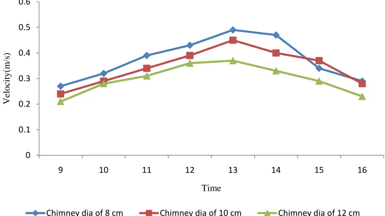
When the collector, chimney height, entrance height (inlet gap) parameters are fixed and the radius of the tower is increased, the mass flow increases Fig. 2 illustrates the velocity as function of time, for three different values of the tower radius. It can be observed that an increase in the tower radius produces an increase in the mass flow. However, due to the increase in the flow area, the velocity decreases in the centre of the tower. Thus with increasing and decreasing chimney diameter the velocity decreases and increases respectively.
Fig. 2: Variation of velocity with respect to variable chimney diameter.
0 0.1 0.2 0.3 0.4 0.5 0.6
9 10 11 12 13 14 15 16
V
elo
city(
m
/s
)
Time
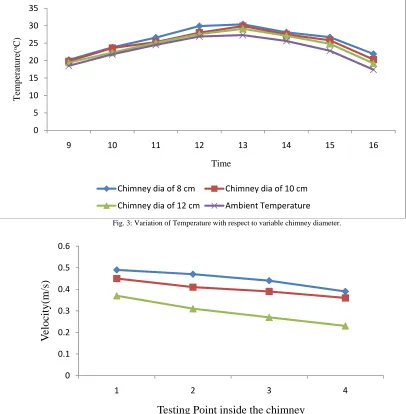
It can be observed that the flow temperature increases towards the centre of the solar chimney, due to the heat exchanges between the ground and the airflow. Temperatures in both collector and chimney increase from sunrise, reach a maximum at about 13, and then decrease with time as solar radiation becomes increasingly weak. This mainly depends on the fact that before dawn the absorbing bed has released almost all heat stored in it the day before, and is first heated by solar radiation after sun rise and its temperature thereafter keeps increasing. In the afternoon, as solar radiation becomes weaker, the heated absorber bed, storing large quantity of heat, releases heat to the air by convection, resulting in continuous reduction of its temperature with time. Close to the centre of the solar chimney, due to the reduction of the flow area, the velocity of the airflow decreases and the temperature starts to rise again. An increase on the tower radius increases the mass flow. Then, a larger volume of air needs to be heated in the cover during the same period of time, causing the flow temperature in the cover to decrease. Fig. 3 shows the temperature along the cover for the analyzed tower radius values. The larger the tower radius, the lower the temperature of the flow in the cover. The increase in the mass flow caused by the increase on the tower radius also results in the reduction of the average temperature of the flow in the tower, as shown in Fig. 3. It can be noted that the flow temperature in the solar updraft tower is always greater than the ambient temperature outside the solar chimney.
Fig. 3: Variation of Temperature with respect to variable chimney diameter.
Fig. 4: Variation of velocity within the chimney height with respect to variable chimney diameter inside the chimney. 0
5 10 15 20 25 30 35
9 10 11 12 13 14 15 16
Temp
er
at
u
re(
oC)
Time
Chimney dia of 8 cm Chimney dia of 10 cm
Chimney dia of 12 cm Ambient Temperature
0 0.1 0.2 0.3 0.4 0.5 0.6
1 2 3 4
V
elo
ci
ty(m
/s
)
Testing Point inside the chimney
3.2 Influence of cover material
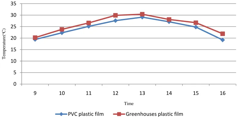
An experimental evaluation of the flow behaviour was performed to analyze the influence of the cover material, using two common materials used in solar devices a thermal diffuser PVC plastic film, plastic film used in greenhouses.
Fig. 5 shows the Experimental results of the ground temperature under the cover during the day. It can be observed that when the materials with higher transmittances to solar radiation are used, the ground temperatures are higher, resulting in higher flow temperatures. Fig. 5 shows the flow velocity in the centre of the tower. Since the flow is generated by buoyant forces created by differences in the temperature of the flow, higher velocities are reached. The definition of the most suitable material for the cover can only be done after an analysis of the financial and the operational aspects. Although glass provides higher temperature and velocity values, it is more expensive, more fragile, and heavier. The greenhouse film has higher transmittance to solar radiation than the thermal diffuser film (allowing a higher value of solar radiation to reach the ground) however; its infrared transmittance is higher than the infrared transmittance of the glass and of the thermal diffuser. Therefore, the thermal losses from the ground to the cover and to the ambient are higher. The plastic film for greenhouses has an average transmittance of (84 ± 6) % to solar radiation and an average transmittance of (67.0 ± 0.7)% to the infrared.
Fig. 5: Variation of temperature with respect to variable collector material.
Conclusion
1. With increasing and decreasing chimney diameter the velocity decreases and increases respectively. 2. The material with higher transmittances to solar radiation increases the ground temperatures and result
in higher flow temperatures.
3. The larger the tower radius, the lower the temperature of the flow in the cover.
Reference
[1] 1.)Xinping Zhou , Jiakuan Yang, Bo Xiao, Guoxiang Hou, Fang Xing,’ Analysis of chimney height for solar chimney power plant’, Applied Thermal Engineering 29 (2009) 178–185 2.)T.P. Fluri, J.P. Pretorius, C. Van Dyk, T.W. Von Backstroma, D.G. Kroger , G.P.A.G. Van Zijl ,’ Cost analysis of solar chimney power plants’, Solar Energy 83 (2009) 246–256.
[2] J.P. Pretorius, D.G. Kroger,’ Critical evaluation of solar chimney power plant performance’, Solar Energy 80 (2006) 535–544. [3] Theodor W. von Backstrom, Thomas P. Fluri,’ Maximum fluid power condition in solar chimney power plants – An analytical
approach’, Solar Energy 80 (2006) 1417–1423.
[4] Cristiana B. Maia, Andre G. Ferreira, Ramon M. Valle, Marcio F.B. Cortez,’ Theoretical evaluation of the influence of geometric parameters and materials on the behavior of the airflow in a solar chimney’, Computers & Fluids 38 (2009) 625–636.
[5] M.A. dos S. Bernardes, A. Voß, G. Weinrebe,’ Thermal and technical analyses of solar chimneys’, Solar Energy 75 (2003) 511–524 [6] A. Koonsrisuk, S. Lorente, A. Bejan,’ Constructal solar chimney configuration’, International Journal of Heat and Mass Transfer 53
(2010) 327–333.
[7] Jorg Schlaich, Rudolf Bergermann, Wolfgang Schiel, Gerhard Weinrebe,’ Design of Commercial Solar Updraft Tower Systems – Utilization of Solar Induced Convective Flows for Power Generation’,journal of solar energy engineering,feb 2005.vol127/117.
0 5 10 15 20 25 30 35
9 10 11 12 13 14 15 16
T
em
per
atur
e(
oC)
Time