DEVELOPMENT OF NEW DESIGN TO
IMPROVE THE PERFORMANCE OF
PERMANENT MAGNET
SYNCHRONOUS RELUCTANCE
MOTOR USING FINITE ELEMENT
METHOD
D. Vimalakeerthy* and Dr.M.Y.Sanavullah** *AVS Engineering College, Salem, Tamil Nadu **V.M.K.V Engineering College, Salem, Tamil Nadu
ABSTRACT
Induction Motors(IM) are preferred as the most common drive for industrial and civil applications due to their simple construction and robustness. But they are not suitable when the application requires speed regulation. In several cases high torque, high efficiency, and simple controllability are often desired. Permanent Magnet Synchronous Reluctance Motor “PMSRM” has gained interest due to several factors like reduced cost, ability to operate at near zero speed even at full load and flux weakening capability for spindle and traction applications. As the high field strength of neodymium-iron-boron (NdFeB) magnets become commercially available with affordable prices, PMSRMs are receiving increasing attention due to their high speed, high power density and high efficiency. A modified design in the location of permanent magnets in the flux barriers of PMSRM is proposed and its results are validated to improve the performance. Finite Element Method(FEM) is used to analyze the design parameters.
Keywords — Permanent Magnet, Synchronous Reluctance Motor Design and Finite Element Method.
I. INTRODUCTION
Permanent Magnet Synchronous Reluctance Motors are receiving much attention due to their high speed, power density and efficiency characteristics[1]. PMSRMs are preferred due to the following advantages[2]. (1)The permanent magnets made of rare earth and neodymium have lower inertia compared with Induction Motor because of elimination of rotor cage. Hence torque to inertia ratio of PMSRM is higher. (2)As PMSRM has negligible rotor losses, their efficiency is high. (3)PMSRM has the excitation in the form of the rotor magnet, hence no external source of magnetizing current for excitation is required like an induction motor. (4)Since rotor losses in PMSRM is small, the loss in the form of heat is avoided which improves the performance of the motor. (5)PMSRM is smaller in size and has lesser weight. It is suitable for the applications where the size of machine is limited.
and efficiency levels when compared with conventional control[7]. Proper implementation of flux weakening control requires the knowledge of synchronous machine parameters. The most common parameters required for the implementation of such advanced control algorithms are
Ld - the direct axis self- inductance
Lq - the quadrature axis self- inductance and mag - the permanent magnet flux linkage.
Prior knowledge of the previously mentioned parameters, and the number of pole pairs p, allows for the implementation of torque control. The required parameters determine the linearized representation for the d-axis reactance Xd, q-axis reactance Xq, and permanent magnet excited voltage Eo. The non-linearity of certain types of salient-pole synchronous machines has made it difficult to apply these control rules.
II. LOCATION OF PERMANENT MAGNETS
PMSRMs are now very popular in a wide variety of industrial applications. Majority of PMSRMs are constructed with the permanent magnets mounted on the periphery of the rotor core. Such motors are called Surface Permanent Magnet Synchronous Motors(SPMSM) [2]. When permanent magnets are buried inside the rotor core the motor not only provides mechanical ruggedness but also opens a possibility of increasing its torque capability. By designing a rotor magnetic circuit such that the inductance varies as a function of rotor angle, the reluctance torque can be produced in addition to the mutual reaction torque of synchronous motors. This class of Interior Permanent Magnet Synchronous Motors(IPMSM) can be considered as the combination of Reluctance Synchronous Motor and the Permanent Magnet Synchronous Motor. This is now very popular in industrial and military applications by providing high power density and high efficiency compared to other types of motors. The proposed design called Permanent Magnet Synchronous Reluctance Motor involves embedding of permanent magnets in the flux barriers of the rotor. Figure 1 shows different locations of permanent magnets in rotor.
Figure 1. Different Locations of Permanent Magnets in Rotor
III. ANALYSISOFPMSRM
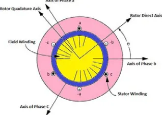
A 4-pole Permanent Magnet Synchronous Reluctance Motor is shown in Figure 2. It has 3-phase stator winding and a salient rotor. The stator windings are identical and displaced 120° from each other. Since the stator winding of PMSRM is sinusoidally distributed, flux harmonics in the air gap contribute an additional term to the stator leakage inductance. Hence, the equations which present the behavior of the PMSRM can be obtained from the usual equations of a conventionally wound field synchronous machine. In PMSRM, the excitation winding does not exist. Hence, both the field winding and damper winding equations of Park's equations are eliminated. The basis for the d-q equations for a Permanent Magnet Synchronous Reluctance Motor can be obtained in a regular way.
These d-q equations express the behavior of the physical stator and rotor currents in a reference frame which is rotating with the rotor of the machine in much the same manner as for a wound field synchronous machine (rotor reference frame). These voltages form a constant amplitude rotating vector in the d-q plane. When the rotor rotates at the same angular velocity as the angular velocity of the rotating voltage vector, (modified by the number of pole pairs), the voltage vector appears to be stationary with respect to the rotor reference frame. In this case, the angular relationship between the stator voltage vector and the d-q axes as the two components are described as
ds
d s ds r qs
d
v
r i
dt
--- (1)qs
q s qs r ds
d
v
r i
dt
--- (2)where
ds
L i
ls dsL i
md dsL i
ds ds
--- (3)qs
L i
ls qsL i
mq qsL i
qs qs
--- (4)Here Lls , Lmd and Lmq are the stator leakage inductance, direct axis magnetizing inductance and quadrature axis magnetizing inductance, respectively. The quantity rs is the stator resistance per phase. The electromagnetic
torque is identical to that of Synchronous Machine given by
3
(
)
2 2
e ds qs qs ds
P
T
i
i
--- (5)Here Te is the electromagnetic torque and P is number of poles.
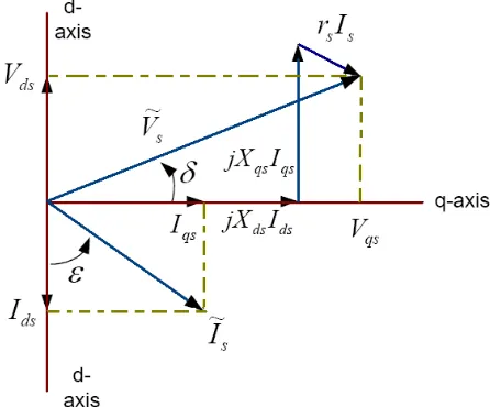
The angular relationship between the stator voltage vector and the d-q axis is shown in Figure 3.
Figure 3. Phasor diagram for Synchronous Reluctance Machine
In phasor notation:
Vs = rsIs +jXds Ids + jXqsIqs --- (6)
The value of currents can be obtained in terms of steady state voltage as
2 2
e qs qs s ds ds
s e ds qs
L V
r V
I
r
L L
2 2
e ds ds s qs qs
s e ds qs
L V
r V
I
r
L L
--- (8)Neglecting stator resistance
&
qs ds
ds qs
e ds e qs
V
V
I
I
L
L
--- (9)Here e is the angular velocity of the rotating reference frame.
IV. DETERMINATION OF ROTOR PARAMETERS
It is understood from the discussion in earlier works, that the advantages of a PMSRM is highly dependent upon the saliency ratio Ld/Lq[8]. In this section use of Finite Element Method to quantify the saliency ratio is studied. Four pole configuration of Figure 2 is considered. Specifically, the rotor is assumed to be constructed of “packets” of thin laminations. These packets of steel are assumed to be separated by a suitable insulator, plastic laminate or epoxy-like material. All of the lamination segments are assumed to be equally spaced. Also, the machine is assumed to have 24 slots (2 slots/pole/phase) with a tooth width over tooth pitch ratio of 0.54. The sum of “n(Wiron+Wins)” is always chosen to be equal to the width of one stator teeth to limit pulsating fluxes in the
stator teeth. In practice, values of n=1 and n=2 were investigated. For the purpose of comparison between different geometries it is useful to define the ratio
Kw = Wins / Wiron --- (10)
where Wins and Wiron represent the width of insulation and width of iron. Clearly, when Kw=0, the rotor is assumed
to be completely made of iron, (i.e. no saliency). When Kw=1 the rotor is constructed of lamination segments in
which the air space and lamination segments are equal.
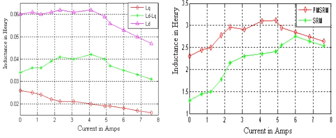
Figure 4. Calculated d-q axes inductances Figure 5. Ld / Lq Vs Current of SRM and PMSRM
Figure 4 shows the d axis and q axis inductance for different values of current. It is seen that the value of d-axis inductance is always greater than the value of q-axis inductance for different values of current. Figure 5 shows the plot of the saliency ratio Ksaliency=Lmd/Lmq as a function of Kw. From the Figure 5 it is found that even at lower
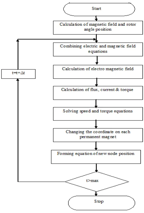
Figure 6. Flow chart of Finite Element Method to estimate parameters of PMSRM
V. DESIGNSYNTHESIS
The name plate details of the PMSRM is given in Table 1.
Power 0.5kW
Rated Speed 1500 rpm
Rated Current 3.46A
Frequency 50Hz
Rated Voltage 380 V
Table 1. Name plate details of PMSRM
A. Stator Geometry
reluctance motors and at the same time eliminates its several disadvantages. The overall view of the motor is as shown in the Figure 7.
Figure 7. Permanent Magnet Synchronous Reluctance Motor. B. Rotor Geometry
Adding the proper quantity of permanent magnets into the PMSRM rotor core is another way to improve the operating performance of this motor[16]. In this case, the motor is similar to an Interior Permanent Magnet Motor[9]. However, the amount of permanent magnets used and the permanent magnet flux-linkages are smaller with respect to the conventional Interior Permanent Magnet Motors. Thus, the proposed motor can be called as Permanent Magnet Synchronous Reluctance Motor (PMSRM).
Figure 8. Proposed PMSRM
The rotor geometry can be obtained to meet the desired criteria and manufacturing limits such as minimum width of ribs and number of flux barriers. As it was mentioned before, to improve the efficiency of the motor some Ferrite magnets are placed in the rotor as shown in Figure 8. One of the features considered in the design of this motor is the magnetization of the Ferrites using stator windings. This feature will cause a reduction in cost and ease of manufacturing [10][13]. Figure 8 shows the rotor with flux barriers and permanent magnets inside the core. The amount of the ferrite placed in the rotor core is limited by the geometry of the rotor and also the material cost.
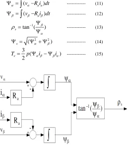
VI POSITION OF ROTOR PHASE ANGLE
In PMSRM it is essential to determine the position of rotor to synchronize the stator current vector and rotor position. As the speed sensors need the extra hardware that increases the cost and the size, sensor less control of PMSRM has been used in recent researches[11]. Since the rotor of PMSRM follows the flux, the position of rotor and fluxes are changed together and it is possible to extract the rotor position by detecting of flux position. Therefore in this method the rotor position is estimated using flux linkage. In this approach, torque ( Te ), speed
(r ) and flux linkage phase angle ( ρs ), in both transient and steady states, is calculated by using the estimated
stator flux linkage ( ψs ), and its components (ψ,ψ) in stationary reference frame.The difference between λ, the
flux linkage in equation (1),(2),(3) and (4) with flux linkage ψ is that, ψ is the hybrid flux linkage obtained by multiplying the actual flux linkage by angular frequency. The equations of these calculations are shown in the following equations
(
v
R i dt
a a)
--- (11)(
v
R i dt
a)
--- (12)1
tan (
)
s
--- (13)2 2
(
)
s
--- (14)3
(
)
2
eT
p
i
i
--- (15)Figure 9. Rotor Phase angle detection
Figure 10. Comparison of reluctance torque using FEM Figure 11. Output Torque with different current Angles
The total resulting torque is the summation of reluctance torque and permanent magnet torque. The values of reluctance torque, permanent magnet torque and the resulting torque are calculated and shown graphically in the Figure11.
VII TORQUE RATIO
The performance of the PMSRM in comparison with the Induction Motor is evaluated by torque ratio
(1
mq)
mdm md
r
m i
r
L
L
L
L
T
L
T
L
--- (16)The ratio of torques depend on three ratios, (1)the ratio of the Synchronous Reluctance Motor d-axis magnetizing inductance corresponding to the induction magnetizing reactance md
m
L
magnetizing to total rotor inductance ratio m r
L
L
(3) the ratio of air gap saliency ratio mqmd
L
L
. Saliency ratio upto7 to 8 have been reported. The inductance motor magnetizing reactance range from 1.0 to 2.0 per unit while the rotor leakage reactance is in the range of 0.08 to 1.2 per unit. Practically ratio of synchronous reluctance d-axis magnetizing reactance to induction motor magnetizing reactance depend primarily on the width of the rotor[12]. VIII POWER LOSS RATIO
PMSRM is actually capable of less torque for the same amplitude of stator current. But the losses of the induction and PMSRM is not same since the Induction Motor must sustain rotor slip frequency losses to produce the torque[14]. On considering only copper losses the power loss in the PMSRM is
2
3
2
r s s
P
I r
--- (17) while loss in the Induction Machine is given by2 2
3
(
)
2
i s s r r
P
I r
I r
--- (18)where Is and Ir represent peak amplitude of stator and rotor current respectively. The total copper loss depends
on losses in both stator and rotor circuits. If the machine is loaded to about rated current then the stator and rotor currents are given by
|
I
r| 0.85 |
I
s|
--- (20)The stator referred value of rotor resistance for most machines varies from 0.8 to 1.3. For many applications, high effiency, low slip machines are preferred making a choice of rotor resistance on the low side of this range preferable[15]. So a nominal value of rotor resistance is selected as
|
r
r| 0.85 |
r
s|
--- (21) Thus the ratio of power loss becomes0.634
rs
P
P
--- (22)IX. CONCLUSION
A new design in the rotor of the Permanent Magnet Synchronous Reluctance Motor is proposed. With respect to the conventional Synchronous Reluctance Motor, this motor offers better torque capabilities. . In this paper Finite Element Method is used to obtain the inductance. Effects of the magnets on d-q inductances were studied. A comparison between reluctance torque of Synchronous Reluctance Motor, Induction Motor and PMSRM was performed. It has been shown that the proposed PMSRM substantially improves the performance due to modified rotor geometry. Computer simulation and the experimental result for the PMSRM show the effectiveness of the proposed method.
NOMENCLATURE
FEM - Finite Element Method IM - Induction Motor
IPMSM - Interior Permanent Magnet Synchronous Motor PM - Permanent Magent
PMSRM - Permanent Magnet Synchronous Reluctance Motor SPMSM - Surface Permanent Magnet Synchronous Motor SRM - Synchronous Reluctance Motor
Ir - peak amplitude current of rotor
Is - peak amplitude current of stator
ids - direct axis current
iqs - quadrature axis current
Ksaliency - saliency ratio
Kw - ratio of width of insulation to width of iron
Lls - stator leakage inductance Lm - motor magnetizing inductance
Lmd - direct axis magnetizing inductance Lmq - quadrature axis magnetizing inductance Lqs - quadrature axis inductance
Lr - total rotor inductance
P - number of poles p - pole pairs
Pi - Power loss in induction machine
Pr - Power loss in rotor
Ps - Power loss in stator
rr - rotor resistance per phase
rs - stator resistance per phase
Te - electro magnetic torque
Vα, Vβ - voltage vectors in stationary reference frames
Vd - d axis voltage
Vq - q axis voltage
Vs - stator voltage
Wins - width of insulation
Wiron - width of iron
Xds - direct axis reactance
Xqs - quadrature axis reactance ρs - fux linkage phase angle
ψ,ψ - hybrid stator flux linkage components
X. REFERENCES
[1] M. Kondo, K. Kondo, Y. Fujishima, S.Shinji,”Rotor desing of “ Rotor desing of Permanent Magnet Synchronous Motor for Railway Vehicle”, IEEJ Trans.IA, vol. 124, no.12, 2004.
[2] N. Bianchi, S. Bolognani, “Interior PM synchronous motor for high performance applications”, Proceedings of Power Conversion Conference, vol. 1, pp. 148-153, April 2002.
[3] D. J. Sim, D. H. Cho, J. S. Chun, H. K. Jung, and T. K. Chung, “Efficiency optimization of interior permanent magnet synchronous motor using generic algorithms,” IEEE Trans. Magn., vol. 33, no. 2, pp. 1880–1883, 1997.
[4] T. Ohnishi and N. Takahashi, “Optimal design of efficient IPM motor using finite element method,” IEEE Trans. Magn., vol. 36, no. 5, pp. 3537–3539, 2000.
[5] T. M. Jahns, G. B. Kliman, and T. W. Neumann, “Interior permanentmagnet synchronous motors for adjustable-speed drives,” IEEE Trans. Ind. Applicat., vol. 22, no. 4, pp. 738–747, 1986.
[6] G. H. Kang, J. P. Hong, G. T. Kim, and J.W. Park, “Improved parameter modeling of interior permanent magnet synchronous motor based on finite element analysis,” IEEE Trans. Magn., vol. 36, no. 4, pp. 1867–1870, 2000.
[7] A.Kiyoumarsi, M.R.Hassanzadeh and M. Moallem, “A New Analytical Method on Interior Permanent Magnet Synchronous Motors”, Scientica Iranica, vol. 13, No.4, pp. 364-372, October 2006.
[8] B. V. Litvinov and O. B. Davydenko, “A Synchronous Reluctance Motor with a Laminated Rotor” Russian Electrical Engineering, ISSN 1068-3712, Vol. 80, No. 1, pp. 29–32. © Allerton Press, Inc., 2009.
[9] Li Liu, Wenxin Liu and David A. Cartes ,”Permanent Magnet Synchronous Motor Parameter Identification using Particle Swarm Optimization”, International Journal of Computational Intelligence Research, ISSN 0973-1873 Vol.4, No., pp.211–218, 2 (2008). [10] S. Morimoto, M. Sanada, Y. Takeda, “Performance of PM assisted synchronous reluctance motor for high efficiency and wide constant
power operation,” IEEE Transactions on Industry Applications, vol. 37, no. 5, pp. 1234-1240, September/October 2001.
[11] Tsuyoshi Hanamoto, Ahmad Ghaderi, Muneto Harada, Teruo Tsuji, "Sensorless speed control of synchronous reluctance motor using a novel flux estimator based on Recursive Fourier Transformation," icit, pp.1-6, 2009 IEEE International Conference on Industrial Technology, 2009
[12] Thierry Lubin,Hubert Razik, and Abderrezak Rezzoug, “On-line efficiency optimization of a synchronous reluctance motor” Electric Power Systems Research, Volume 77, Issues 5-6, Pages 484-493, April 2007.
[13] B. Singh, B.P. Singh, and S. Dwivedi, “A review of sensor reduction techniques in permanent magnet synchronous motor drives,” 10.2316/Journal.203.2009.1.203-3714, (203) International Journal of Power and Energy Systems - 2009.
[14] R. Lateb, N. Takorabet, F. Meibody-Tabar, A. Mirzaian, J. Enon, and A. Sarribouette, “Performances comparison of induction motors and surface mounted PM motor for POD marine propulsion”, in Conf. Rec. IEEE-IAS Annu.Meeting. 2005.
[15] Albert W.-J. Hsue, M.-T. Yan,”Comparison on linear synchronous motors and conventional rotary motors driven Wire-EDM processes”, Journal of Materials Processing Technology,Volumes 192-193, Pages 478-485, 1 October 2007
BIOGRAPHY
Mr. D. Vimalakeerthy, was born in Tamil Nadu, India. He received B.E degree in Electrical and Electronics Engineering and M.E degree in Power Electronics and Drives. Currently he is working as a Assistant Professor in Electrical and Electronics Engineering Department at AVS Engineering College, Salem and pursuing his PhD in Anna University, Coimbatore. His research interest is Design improvement of Synchronous Reluctance Motor and Finite Element Analysis.