e-ISSN: 2278-7461, p-ISSN: 2319-6491
Volume 5, Issue 4 [March 2016] PP: 35-43
Acrylic Prosthetic Limb Using EMG Signal
B . Sumathy
1, R. Aarthy
2,J. Ashvini
2,G. Samyukta
2,R. Sowbhaghyavathi
2 1 Assistant Professor, 2 Final Year Students, Instrumentation and Control EngineeringSri Sai Ram Engineering College, Chennai – 44.
Abstract: The paper deals with the development of a prosthetic limb made of acrylic sheet using
electromyography signals for the people who lost a part of their limb due to circulation problems from atherosclerosis or diabetes, traumatic injuries occurring due to traffic accidents and military combat, cancer or birth defects. Electromyography (EMG) is a technique for evaluating and recording the electrical activity produced by skeletal muscles. An electromyography detects the electrical potential generated by muscle cells when these cells are electrically or neurologically activated. Measured EMG potentials range between 2 millivolt to 4 millivolt depending on the muscle under observation. The two surface electrodes are attached to the healthy limb and sense the muscle contraction when a movement is made. This output is given to the arduino microcontroller, this controller is programmed that, it acquires the angle and transformation link obtained due to the locomotion of normal limb. The output signals are given to the servo motor through servo driver and then to the prosthetic limb. The methodology adapted here provides locomotive action for the prosthetic limb. The major advantage of the proposed system is that, usage of acrylic sheets reduces the weight of the prosthetic limb to a greater extent. This cost effective acrylic prosthetic limb avoids any irritation or side effects to the one who carries it.
Keywords: Acrylic, Arduino, Prosthetic Limb, Servo motor.
I.
INTRODUCTION
Prosthetic is an artificial extension that replaces a missing body part. They are used to replace parts lost by injury or missing from birth or to supplement defective body parts [2]. Prosthetic design features of artificial limbs are light weight, compact and dexterous that mimics human anatomy and maintain a high lifting capability [9]. Prosthesis is a device that can help restore some of the functionality to the user [6]. Myoelectric prostheses of the upper limb increase range of motion and improve overall function of the upper limb with missing hands [4]. People with lower limb amputees also struggle and suffer from easy navigation. These challenges can be attributed by the use mechanically prosthetic legs [5]. A deficient limb person can lead an independent life by the help of prosthesis [6].
Myoelectric or EMG signal are acquired using suitable sensors (either from surface of the body or from muscle) from the human body are widely used in actuating prosthetic devices. These devices intelligently recognize limb motion of the person and the pulses are generated by using microcontroller and the respective motors. The motor is driven for movements of the hands and wrist, hand open, hand close, wrist flexion, wrist extension etc. Restricted movement was allowed while recording EMG signals from elbow or wrist flexors / extensors during isometric contractions are recorded by the surface electrodes are sufficient to control the movements of a virtual prosthesis [2]. Due to the fast advances in medical technology worldwide, rehabilitation systems are currently used by patients after a major operations, chronic pain, sensory loss, stroke, unpredicted pain, severe accident, orthopaedic anarchy, brain injury, Parkinson’s disease, psychological disorder, sports – related injury and by older individuals [10 ,11]. Not even routine activities in day to day life are not self sufficient [7].
and discussion and end up with conclusion and references.
II.
LITERATURE
SURVEY
In [18], the authors devised EMG position control active ankle foot prosthesis. They proposed two control schemes to predict the amputees’ ankle position such as neural network and muscle model approach. They also concluded that biomimetic EMG controller provided more natural movement pattern. In [19], the authors presented a methodology where the impedance of the orthotic joint is modulated throughout the walking cycle to treat drop foot gait. Here, they used variable impedance to get a conventional output. Thus, they achieved the normal walking ability for people affected with drop foot gait. In [8] , the authors suggested an unambiguous taxonomy applicable to control systems for prosthesis. Also a functionally partitioned model of the prosthesis control problem is presented. In [7], the authors S. Sudharsan and Dr. E. Chandrasekaran designed and developed the EMG controlled prosthetics limb. Extraction of EMG signal was taken from the patient’s healthy arm and passed their control signal to the prosthetic arm. The delivered signals to the prosthetic arm were used to drive the motors and control mechanism was done. In Myoelectric Teleoperation of a complex Robotic Hand [20], the author has followed a procedure in converting the Myoelectric signal generated by the operated muscles during movement into robot commands replicating the motion. Here an unusual method of Teleoperation of complex anthropomorphic robotic hands is dealt with. Thus they achieved a feasible outcome of operating a myoelectric operation of a complex robotic hand.
The authors HofAL , Geelen BA, Van den Berg J. concentration were totally focused on calf muscle in order to get an efficient level of walking by making muscles to act as a spring. Calf muscle’s level of walking was determined by means of an EMG signal to force processor, based on a muscle analogue. By this, they attained a high efficiency in walking more or less similar to a natural walk [21]. In this paper, the author has concentrated on the characteristics of walking. Since the mechanics of human walking is often modeled as an inverted pendulum, the COM (Centre of Mass) has been a significant concept. As kinetic and potential energy were also involved here, an energy balance was checked to ensure net change in mechanical energy [22]. In Design of a Human Hand Prosthesis paper, five fingers were mainly concentrated. The author incorporates five individually actuated fingers in addition to powered thumb roll articulation. Finger tip grip role is displayed via LEDs for feedback control. Thus the author formulated a method to replace a diseased hand using human hand prosthesis [23]. In [24], two computer controlled devices for leg rehabilitations were presented. They are (i) external knee prosthesis for trans-femoral amputees. (ii) A force-controllable ankle-foot Orthosis to assist individuals suffering from drop-foot, a gait pathology resulting from muscle weakness in ankle dorsiflexors. For the ankle foot Orthosis joint stiffness is automatically adapted to permit a smooth and biological heel strike to fore foot patients. Thus it paved way for a greater improvement in patient stability and dynamic cosmesis. This also helped in providing a wider range of locomotory functions. The author Mohan C, Vinod Kumar Giri has involved controlling a motor in forward and reverse direction using electromyogram (EMG) signal without any feedback. To study microcontroller applications, real time based EMG based prosthetic hand was implemented. This project gives knowledge of component level and system level design. This project includes extraction of EMG signal, design of signal conditioning circuit and development of overall system. The electromyogram (EMG) signal is the electrical physiological signal of activation of a motor unit. This helped for designing a control device for a rehabilitation device like hand prosthesis in future [25].
III.
PROPOSED METHOD
In the proposed Method, the development of Prosthetic limb using EMG signals is designed. The Prosthetic limb functions according to the input from the normal limb. It is constructed using weightless materials with less hardware components. This cost effective prosthetic limb enables the end user to walk with a great comfort. The program to the prosthetic limb is embedded in an Arduino microcontroller which serves as an open source platform where one electric component can interact with another.
Fig 1: Block Diagram
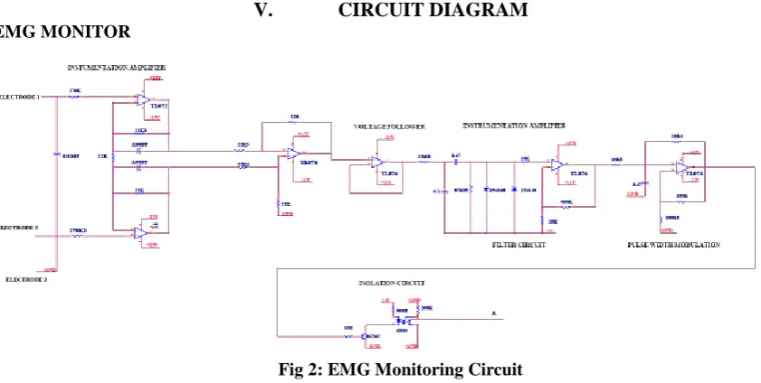
Two electrodes are placed on the healthy limb and another two electrodes are referred to ground. When the healthy limb moves, muscle contractions are made. These muscle contractions are sensed by surface electrodes which produces a voltage of 2 millivolt to 4 millivolt. This voltage is given to EMG circuit. EMG circuit consists of Instrumentation amplifier, rectifier, filter and regulator. After being processed by the EMG circuit, the signals are given to the arduino microcontroller. This arduino microcontroller is already preprogrammed such that the prosthetic limb acquires the accurate step and angle made by the healthy limb. The Limit Switch is used for secondary purpose. Both these inputs are converted to digital signals by ADC (Analog to Digital Converter) before being sent to the Arduino microcontroller. Two servo motors are placed above knee and below knee respectively. 24 millivolt of input signal is passed to the servo driver from the Arduino microcontroller. This actuates the servo mechanism to drive the servo motor. This enables the prosthetic limb to function according to the input given by the normal limb.
V.
CIRCUIT DIAGRAM
EMG MONITOR
Fig 2: EMG Monitoring Circuit
Fig 3: Servo Motor Control System
Wiring a 110 or 220 volts split phase capacitor start AC motor to achieve a dual voltage 110 or 220 volts connection and to be able to run the motor in both forward and reverse direction can be achieved by knowing the order and arrangement of its internal coil winding connection and its associated internal electrical components. An LCD consists of two glass panels, with the liquid crystal material sand witched in between them.When the LCD is in the off state, light rays are rotated by the two polarizers and the liquid crystal, such that the light rays come out of the LCD without any orientation, and hence the LCD appears transparent.
VII.
MATHEMATICAL MODEL
Kinematic is the motion of point, object, and body, etc.Without considering the motion of the object and force that may cause motion. There are a variety of quantities are associated with the motion of limb-displacement (&distance), velocity (&speed), acceleration and time. Knowledge of each of these quantities provides descriptive information about the limb’s motion. These are given by kinematic equations and are as followed,
d = Vi t + ½ at2 (1)
Vf =Vi + at (2)
Vf2=Vi2 + 2ad (3)
d= ((Vi+Vf)/2) t (4)
Where d=distance, Vi=initial velocity, Vf=final velocity, a=acceleration due to gravity, t=time taken.
Steps to derive kinematics model Assign D-H co-ordinates frame. Find link parameters.
Transformation matrices of adjacent matrix. Calculate kinematics.
Derive Newton-Euler equation.
D-H co-ordinates frame
(6) Ai =transformation matrix, T= general link transformation matrix.
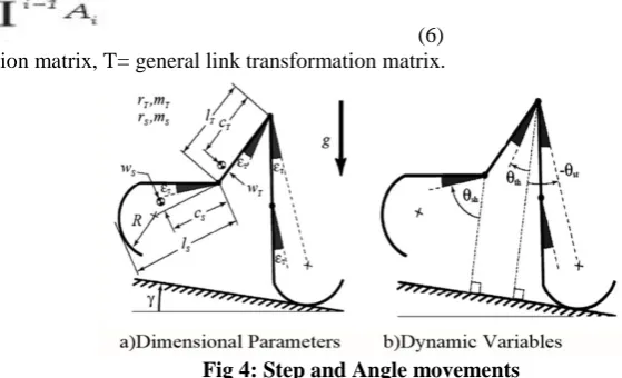
Fig 4: Step and Angle movements
ΘSH=SHANKANGLE, ΘTH=THIGH ANGLE, ΘST=STANCE ANGLE
NEWTON-EULER EQUATION
Combination of translational and rotational equation,
F=ma (7)
EULERS
It has 2 laws,
(1) Linear momentum,
P=mv (8) P=momentum (quantity of motion of moving body)
m= mass v=velocity
(2) Angular momentum, Based on w (omega)
This kinematics exhibits motion in prosthetic limb ,
The newton euler equation has been used to obtain the equations of motion of this model and will yield the following kinematic equtions, where,
(9)
w=angular velocity wa =angular acceleration V=velocity of each frame Va =acceleration of each frame
Vc =velocity of center of mass of each link Vac =acceleration of center of mass of each link.
ANGLE EQUATIONS
(11) Where θa, θb = joint angles, R=radius, V=velocity, l=length
ANGLETABLE FOR PROSTHETIC LIMB
Table 1 shows the range of motion for the human leg, while the parameters corresponding to the robot leg are based on a previous study by Hernandez‐Santos et al [26]. Note that some ranges of motion of the humanoid robot do not correspond to the human leg, due to the interference between mechanical parts. The local frames (Xi, Yi, Zi) are assigned to each joint according to the Denavit‐Hartenberg (DH) convention [27]. Consider the base frame (X0, Y0, Z0) at the centre of the waist as the global reference frame. Since the general kinematic structures of the left leg of a humanoid robot are identical to those of the right leg, this paper assigns the same coordinate frames for the left and right limbs for convenience of analysis.
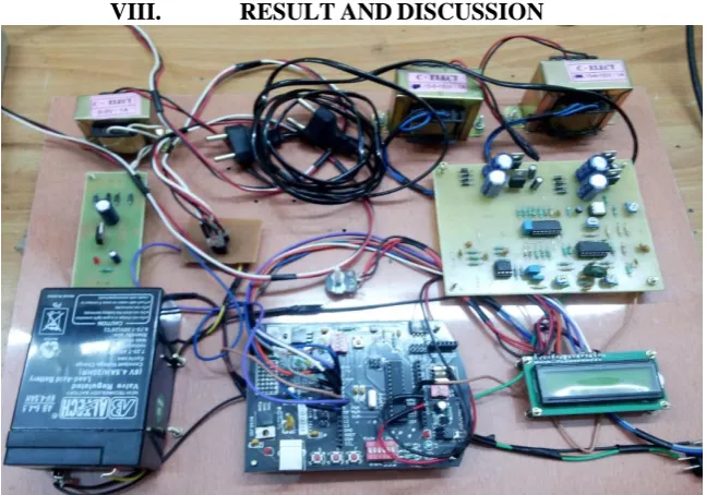
The hardware which contains Power supply, EMG circuit in that Instrumentational amplifier, Rectifier etc, then Arduino micro controller, Servo driver and servo motor . The result of our project is calculated experimentally for waist and knee movement. The prosthetic limb acquires an accurate input from the healthy limb movement. The output obtained is exactly the same as the input and thus prosthetic limb functions as a normal limb.
Table2: Joint range of Motion for Knee and Waist
In our proposed method, we are taking only the angles for waist and knee joint. Waist is characterized for pitch, roll and yaw. Pitch which is the rotational movement about X- axis (i.e., up/down movement), yaw which is about Y- axis movement (i.e., side to side swing movement) and roll is the rotation about Z- axis (i.e., rotator movement) and knee has only pitch joint.
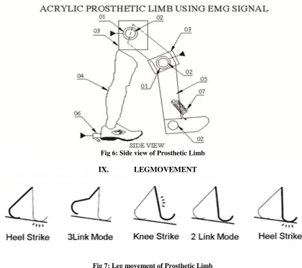
Fig 6: Side view of Prosthetic Limb
been considered. The relation between before and after of the impact has been solved in forward analysis.
X.
CONCLUSION
The electromyogram (EMG) signal is the electrical physiological signal of activation of a motor unit associated with a contracting muscle and serves as a potential resource. The movement of the prosthetic limb with the help of the signals acquiring from the healthy limb is our result. Two electrodes which are placed on the normal limb will be sending its signal to the Arduino microcontroller and in turn it will be sending the signal to the servo motor thereby the movement of prosthetic limb takes place as per the movement of normal limb with same angle and steps. The prosthetic limb made use of acrylic sheet using electromyography signals has Less Weight, Reliable, Cost-effective, Durable, High performance, No side effects and it cannot be applied for the amputees with no limbs. The project can be implemented to the amputees who lost both of their limbs. Further it can be improved to animals as helping aid to supplement their own missing or impaired limbs.
REFERENCES
[1] Nayan M Kakoty and Shyamanta M.Hazarik, “Bio signals controlled prosthetic hand” , Tezpur University,School of education,Tezpur,India.
[2] Chandrashekhar P. Shinde, “Design of Myoeletric Prosthetic arm ” International Journal of Advanced Science,Engineering and Technology,Dept. of Electronics, ISSN 2319-5924, vol 1, Issue 1,2012,pp 21-25, TKIET Warananagar, Kolhapur, India .
[3] Nizam Uddin Ahamed1, Kenneth Sundaraj1, Badlishah Ahmad1, Matiur Rahman , Md. Asraf Ali1, Md. Anamul Islam1 and Rajkumar Palaniappan “Rehabilitation systems for physically disabled patients: A brief review of sensor-based computerised signal- monitoring systems “1AI-Rehab Research Group, Universiti Malaysia Perlis (UniMAP), Kampus Pauh Putra, 02600 Arau, Perlis, Malaysia College of Computer Science and Information System, Najran University, Kingdom of Saudi Arabia.
[4] Dr. Craig W. Martin, Senior Medical Advisor “Upper Limb Prostheses”A Review of the Literature With a Focus on Myoelectric Hands ,By WorkSafeBC Evidence-Based Practice Group , February 2011. [5] “Control of powered prosthetic legs” - Pdf
[6] Erin Strait “Prosthetics in developing countries” , Prosthetic Resident, January 2006, pp 1-40.
[7] S.Sudarsan,Dr. E. Chandra Sekaran “Design and Development of EMG controlled Prosthetics Limb”, Procedia Engineering,Dept of Electrical and Electronics Engineering, Coimbatore Institute of Technology, TamilNadu,, 38(2012) pp 3547-3551.
[8] Anders Fougner, Øyvind Stavdahl, Member and Peter J. Kyberd, Yves G. Losier, and Philip A. Parker, “Control of Upper Limb
Prostheses: Terminology and Proportional Myoelectric Control - A Review “.
[9] W. Ganong, Review of Medical Physiology, 20th ed . Mc-Graw-Hill, Newyork., 2001, pp. 72–74. [10] Majdalawieh O, Gu J, Bai T, Cheng G.Biomedical signal processing and rehabilitation engineering: a
review. IEEE Conf on Communications, Computers and signal Processing 2003, 2:1004-1007.
[11] Pantelopoulos A, Bourbakis N. A survey on wearable biosensor systems for health monitoring. 30th IEEE Int Conf on Engineering in Medicine and Biology Society 2008, pp. 4887-4890.
[12] Jun-UK chu,Member, IEEE, Inhyuk moon,” A Supervised Feature- Projection- Based Real Time EMG Pattern Recognition for Multifunction Myoelectric Hand Control”, IEEE/ASME Transactions on Mechatronics, vol 12,no. 3,June 2007,pp. 282-290.
[13] K. Ziegler-Graham, E. J. MacKenzie, P. L. Ephraim, T. G. Travison, and R. Brookmeyer, “Estimating the prevalence of limb loss in the united states: 2005 to 2050,” Arch. Phys. Med.Rehabil., vol. 89, no. 3, 2008, pp. 422–429.
[14] A. Esquenazi and R. H. M. III, “Rehabilitation in limb deficiency. 4. limb amputation,” Archives of Physical Medicine and Rehabilitation,vol. 77, no. 3, Supplement, 1996, pp. 18–28.
[15] D. R. Merrill, J. Lockhart, P. R. Troyk, R. F. Weir, and D. L. Hankin, “Development of an implantable myoelectric sensor for advanced prosthesis control,” Artif. Organs, vol. 35, no. 3, 2011, pp. 249–252. [16] E. A. Biddiss and T. T. Chau, “Upper limb prosthesis use and abandonment: A survey of the last 25
years,” Prosthet. Orthot. Int., vol. 31, no. 3, 2007, pp. 236–257.
[19] Joaquin A. Blaya and Hugh Herr,”Adaptive Control of a Variable Impedance Ankle Foot Orthosis to Assist Drop-Foot Gait”, IEEE Transactions on Neural Systems and Rehabilitation Engineering, vol.12,no.1, March 2004.
[20] Kristin A. Farry and Ian D. Walker,” Myoelectric Tele operation of a Complex Robotic Hand”, Dept. Of Electrical and Computer Engineering, Rice University, Houston , pp. 502-509, USA.
[21] of AL, Geelen BA, Van den Berg J, “ Calf Muscle Moment, Work and Efficiency in level walking; role of series elasticity.
[22] R.R. Neptune, F.E. Zajac, S.A. Kautz,” Muscle mechanical work requirements during normal walking: the energetic cost of raising body’s center-of-mass is significant “, Journal of Biomechanics 37, 4 November 2004, pp. 817–825.
[23] PaulVentimiglia (LA&E), “Design of Human Hand Prosthesis “, Worcester Polytechnic Institute, April 26,2012, pp. 1-75.
[24] Hugh Herr, Ari Wilkenfeld, Joaquin Blaya ,” Patient-Adaptive Prosthetic and Orthotic Leg Systems “, MIT Cambridge, MA USA.
[25] Mohan C, Vinod Kumar Giri, “DC Motor control using EMG Signal for prosthesis “, Sharda university, Greater Noida, India , M.M.M. Engineering Collage Gorakhpur, UP, India., IJECT , vol. 2, Issue 2, June 2011.
[26] C. Hernández‐Santos, R. Soto, and E. Rodríguez, “Design and Dynamic Modeling of Humanoid Biped Robot e‐Robot”, Proc.
of the IEEE Electronics, Robotics and Automotive Mechanics Conference, CERMA 2011, Cuernavaca, México, pp. 191‐196.
[27] C. Chevallereau, G. Bessonnet, G. Abba, Y. Aoustin, 2009, “Bipedal Robots, Modeling, Design & Walking Synthesis”, Ed. Wiley.