190801-2727-IJET-IJENS © February 2019 IJENS
Development and Optimization of Electro-Chemical
Spray System for Agriculture Fields
Ahsan Rahman, Fahad Abdulrahman Al-Mufadi
College of Engineering, Qassim University, Qassim, Saudi ArabiaAbstract-- This research introduces a novel design for Electrohydrodynamics (EHD) head for agriculture spray system. In the first section, the manuscript detailed different EHD patterning approaches including ring type counter electrodes and their drawbacks. The counter electrode is kept above the nozzle orifice and spray is done by maneuvering contour of electric field in such a way that even with the smaller length of jet, stable spray can be done. For better understanding and evaluation of phenomenon, simulations and comparisons are also performed and radial effect is analyzed. Furthermore, the effect of meniscus response and shape on voltage is analyzed. Manuscript also elaborates and addresses issues like the meniscus generation and ejections at voltage. In the end, based on above results, a novel system is designed and experiments conducted and performed. Design of experiment is also used to optimize the results. It is concluded that the extraction force required to extract the droplets depends upon the viscosity of the solutions.
Index Term--
Electrohydrodynamics, spray, simulations, conejet
I. INTRODUCTION
The pesticides spray system in crop yield has been part of farming form its interception. Different types of spray distribution systems are being used for dispersion. Spray distribution depends on the density of flow of the droplets at a given distant with a specific spray pattern. Nozzle producers have their own approaches to rate the flow pattern distribution. One such method is to arrange containers on a level surface and to measure the level in each after spraying for a certain period of time. Also, flow distribution can be classified into three types on the basis of target surface that is curved in, curved and trapezoid. This grouping of flow distribution varies according to the kind of nozzle and mechanism of spray. Spray impact and distribution vary according to a type of nozzle, pressure, flow rate and Fluid (Jain Sun, Yubin M. 2011).
The pressure spray system can deliver low or high volume of chemicals in controlled manner (Eryilmaz, B., Wilson, B.H., 2006). Thus, spraying quality is directly proportional to the space between nozzles, chemicals and crops (Jelali, M., Kroll, A. 2004). When the distance is not adequate the droplets cannot entirely cover the field and overdose will be happened in areas due to increase of
chemical concentration there is quite high (Sun and Miao, 2011). With this, the sprayer vehicles cannot be perfectly steady, therefore, vibration will occur during the spray application process. In this situation the chemical droplets cannot be distributed uniformly on the crops which will reduce the spraying quality (Clijmans, 2000). As per the agricultural precision systems, the nozzle size should be 200um to 1000um with keeping a safe distance of spraying nozzles to the field between 50 cm to 70 cm (Anthonis et al. 2005). Therefore, there is a strong need to make a system which will provide homogenous drops to the crops for better yield.
Pressure spray system has some inherent problems: there is only one force for the ejection of pesticides solutions and virtually there is no control on drops outside the nozzle, so this causes nonhomogeneous, heavy and uni-directional drops; that means some time overdoses, which in turn can cause serious harm to the crop, especially the sensitive ones.
190801-2727-IJET-IJENS © February 2019 IJENS the crop, especially the sensitive ones. Therefore, there is a
need of adding a new force which can control the movement of drops and can divide the drops in equal and homogeneous parts.
Therefore, there is a need of adding a new force which can control the movement of drops and can divide the drops in equal and homogeneous parts. The purpose of this research is to develop and study system which can improve the quality of the spray system in the agriculture field and improve the inherent problems faced by the spray systems already being used in the field.
This will be done by implementing by passing charged chemical solution through electric field. This process is known as electrohydrodymanics (EHD). William was first to observe EHD, in the presence of a charged piece of amber, a drop of water deformed into a cone. This effect is clearly related to electrosprays, even though Gilbert did not record any observation related to liquid dispersion under the effect of the electric field. In 1750 the French clergyman and physicist Jean-Antoine (Abbé) Nollet noted water flowing from a vessel would aerosolize if the vessel was electrified and placed near electrical ground. He also noted that similarly “a person, electrified by connection to a high-voltage generator, would not bleed normally if he were to cut himself; blood would spray from the wound.”. In 1882, Lord Rayleigh theoretically estimated the maximum amount of charge a liquid droplet could carry; (Rayleigh, 1882) this is now known as the "Rayleigh limit". His prediction that a droplet reaching this limit would throw out fine jets of liquid was confirmed experimentally more than 100 years later (Gomez and Tang, 1994). In 1914, John Zeleny published work on the behavior of fluid droplets at the end of glass capillaries. This report presents experimental evidence for several electrospray operating regimes (dripping, burst, pulsating, and cone-jet). A few years later, Zeleny captured the first time-lapse images of the dynamic liquid meniscus. Between 1964 and 1969 Sir Geoffrey Ingram Taylor produced the theoretical underpinning of electro spraying. Taylor modelled the shape of the cone formed by the fluid droplet under the effect of an electric field; this characteristic droplet shape is now known as the Taylor cone. He further worked with J. R. Melcher to develop the "leaky dielectric model" for conducting fluidsv. By analyzing above two main properties of EHD, the most important in this project are, ionization of the particles (Fenn et al., 2007) and deposition of particles for nanostructures (Salata, 2005) for example to deposit single particles on surfaces. This is done by spraying colloids on average containing only one particle per droplet. The solvent evaporates, leaving an aerosol stream of single particles of the desired type. The ionizing property of
the process is not crucial for the application but may be used in electrostatic precipitation of the particles.
II. ELECTRODE GEOMETRY AND DESIGN
Different types of electrode geometry are under investigation for drop generation through electrostatic inkjet head. But the key feature is to minimize the effect of ground on the yield or reducing the waste of the chemicals by decreasing the applied potential with precise drop position. Therefore, in this section we will summarize the effects of the different position of electrodes for generating precise dripping.
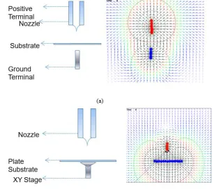
For analysis of different electric field different patterning techniques are studied. The Figure 1 shows the simulations of basic and conventional setup (Grimm, Ronald L. (2006). In electric field simulations, red portion represents the nozzle and the bottom blue portions represent the ground portion. Figure 1 shows the effect of different placements of counter electrodes where arrows specifies the course of the electric field and the color indicates the strength, where black is the most effective and blue is the weakest. The Figure 1(a) shows pin to pin (P2pin) and Figure 1 (b) shows the pin to plate (P2plate) setup. (Choi et al., 2009) It can be seen from the simulations, that electric field is more focused and directed in the case of P2pin setup.
Fig. 1. (a) Pin to Pin setup and (b) Pin to Plate setup
190801-2727-IJET-IJENS © February 2019 IJENS its drawbacks as it lacks speed, accuracy of drop size from
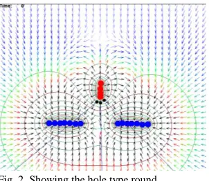
meniscus, placement on substrate and hurdle in designing of multi nozzle head to make possible for the direct writing at the industrial level. Since the components must be combined to make a functional system in order to provide desired services, system-level complexities in architectures. Even some researcher also used multiple counter electrodes to elongate the jet, but that also make dispersion very difficult due to complex nature of geometry and electrodes. Figure 2 shows the effect of counter electrodes below the nozzle.
Fig. 2. Showing the hole type round
But to overcome the above affects this manuscript proposed a new novel idea of patterning through ring counter electrode to resolve the problem of through cone jet. The ring counter electrode is kept above the nozzle orifice. Patterning is done by maneuvering contour of electric field in such a way that even with the smaller length of jet, stable printing can be done. For better understanding and evaluation of this phenomenon, simulations were also performed. From literature, it has been found that radial effects of electric field produce more instability. To analysis the radial effects of electric field, simulations are performed. For further verification, experiments were conducted. For experiment, a new head design is designed, with the ability of moving ground terminal at different position.
III. EQUATIONS AND MODELLING
Electrostatic spray deposition system is a multi-physical system, consists of many variables like voltage, frequency, distance and shapes of electrodes, nozzle deigns and orifice, ink parameters, etc. So, to analyses and study the behavior of each parameter in detail the benefit of simulation analysis (or numerical analysis) can be used. Therefore, for the further analysis of the head, simulations are done to deeply investigate the electrostatic inkjet process in this proposed head by using commercial available software. Figure 3 shows the model diagram of the spray head. The spray head model is designed to analysis the behavior of the head at different parameters. The ground is raised at different heights to analysis the behavior of the head. The various parameters are
also summarized in the Figure 3. In numerical simulation, in order to solve the behavior of EHD spray system the fluid dynamic and electric equation used is
(1)
Where
(2)
(3)
Fig. 3. Finite Element model of the proposed head
And the influence of the polarization forces is ignored because in isotropic and incompressible fluid the permittivity has no gradient and the dielectric force is also equals to zero (Melcher, 1969)
(4)
In order to simplify the problem axis symmetric model is used for the analysis purpose. The region near to the nozzle and the path of the drop was allotted large number of cells to capture the behavior of the problem. Total number of elements for 410μm diameter capillary case was 65700. Moreover, for simulation, areas of higher intensity of electric field at positive and negative terminals are also highlighted. And the contour and field vectors of electric field is analyzed. The electric field is estimated for each case, shown in the Tables by keeping all other parameters constant like the distance between the electrodes, ink and temperature. Thus, for the evaluation of the electrode experiment is conducted. Electric field is estimated at each point to find the optimal distance and voltage of each head to avoid corona discharge and the breakdown of the medium (air) between the positive and negative terminals.
190801-2727-IJET-IJENS © February 2019 IJENS is divided in to three different cases. The different values of a
and b indicates the different placement of the ground for in detail analysis of contour of electric field, strength of electric field and estimation of electric field on the nozzle. For each case different potential is applied from 1kV to 5kV to estimate the behavior. Figure 4 shows the results at case 1 position ground position at 5kV. Moreover, it found that minimum corona discharge and good contour of electric field was observed, when electrodes are away from the tip of the nozzle and also in radius. From the simulations it was evaluated that highest the ground the better the radial effect and the behavior of the spray. Figure 5 shows the droplet generation analysis of the system and effect of field on the nozzle
Table I
Showing the cases and values
Case a b
1 2.5 3
2 2.5 1.5
3 2.5 0
Fig. 4. Effect of Electrical field on the menuics
Fig. 5. Radial Response analysis at different cases and position of ground elecrtode a
IV. EXPERIMENTAL SYSTEM AND VERIFICATION OF SIMULATIONS RESULTS
Due to the complex geometry inside electrostatic nozzle head it’s difficult to model the meniscus shape and the extension in meniscus in detail here. Thus, for the evaluation of the electrode experiment is conducted.
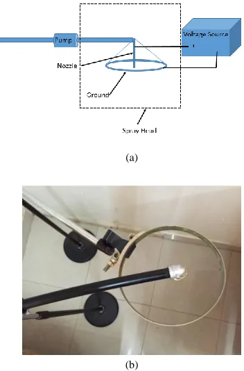
The experiment setup and proposed spray head workable on electrostatic forces specifically designed for this research and study, is shown in the Figure 8. The system consists electrodes, a high voltage source, observation system, chemical supply system, nozzle holder and ground holder. The positive potential is connected to nozzle head for activating the chemical and providing the necessary potential to the chemical for the drop extraction. The liquid pressure is controlled by using the pressure injection. The inlet flow rate is an important parameter to maintain the uniform static pressure in the chemical chamber when the reservoir head is changing due to the ejection of chemicals during the spraying process. The flowrate is selected in the same range as used by the industrial level and manufactures in the data sheet with given nozzle. For the application of voltage DC power-supply is used, which can provide volatge upto 30kV. But in this resaerch the optenial is kept around 5kV. Figure 6(a) shows the schematic diagram of the system and figure 6(b) and (c) shows the physical system steup.
(a)
190801-2727-IJET-IJENS © February 2019 IJENS (c)
Fig. 6. shows experimental setup (a) schematic (b) top view (c) isotropic view
Figure 7 shows the experimnts conducted and results for the above mentioned analysis. Figure 7: shows (a) experiments without gound and applied votlage (b) experiments with ring ground wihout voltage and (c) wet ground electrode after the application of the voltage (charged soultion and ground). It can be seen that the ground electrode gets wet when the voltage is applied to the ground. The drops are coming back to the ground due to the applied voltage which in turn will help to cover both sides of the agriculture plants.
(a) (b)
(c)
Fig. 7. shows (a) experiments without gound and applied votlage (b) experiments with ring ground wihout voltage and (c) wet ground electrode
after the application of the voltage (charged soultion and ground)
To analysis the position of ground, design of experiment techniques is used. The vectors of the electric field are not focused near the cone, which may cause instability in the cone jet or push positively charged droplets outward. Therefore, optimized position of ground is very important. The results of analysis are given below. For the initial analysis interaction and perturbation graphs are used. Different position of silica and voltage is analyzed and modified to find the response on different points. The ground position is kept constant as already explained. The graphically obtained results are shown
in the Figure 8. From figure 8 analysis, region of jet stability is optimized. The graph is divided into different ranges where blue indicates the stable region for the jetting and red indicates unstable region for the jetting. The Figure 10 also shows the unstable and it can be seen that the head performs best when it’s on the tip of the nozzle especially where meniscus is created.
Fig 8. Shows region of stable and unstable jetting and spray
V. CONCLUSION
This research presented experimental study of novel design of electro hydrodynamic spray head design for agriculture spray system through experiments and simulation analysis. Stable and unstable spraying position of the head was analyzed by using design of experiments. The developed system can be implemented without making a major modification in the current available system. The analysis also covers the behavior and detail study of the electric field on and around the nozzle. The main sources of uncertainty seen in the results are believed to be impurity molecules in the working liquid. For future study, this is important source of uncertainty as the impurity molecules entering the system change the effective voltage required during liquid charging process. There is a need to study impurity molecules detaching from the electrode surface and entering the liquid. Another factor which needed to be investigate is the gradual degradation of the electrodes or charging mechanism. Therefore, its recommend that on different material based electrodes should be tested.
ACKNOWLEDGMENT
190801-2727-IJET-IJENS © February 2019 IJENS REFERENCES
[1] Anthonis, J., Audenaert, J., Ramon, H.,Design optimisation for the
vertical suspension of a crop sprayer boom, Biosystems Engineering, vol.90 no. (2), pp. 153–160, 2005.
[2] Choi, K.H.; Rahman, A. ; Ali, A. ; Ko, J.B. ; Dang, H.W. ; Yang, B.S. ;
Doh, Y.H. ; Kim, D.S. Analysis of the Effect of Different Ground Hole Size on Stable Meniscus in Electrostatic Integrated Deposition Inkjet Head, IEEE International Symposium on Assembly and Manufacturing (IEEE ISAM 2009) in Seoul, Korea, pp 159-164, 2009.
[3] Clijmans, L., Swevers, J., Baerdemaeker, J.D., Ramon, H. Sprayer boom
motion, part 1: derivation of the mathematical model using experimental system identification theory, Journal of Agricultaure Engineering, vol 76, no. 1, pp 61-69, 2000.
[4] Fenn, J. B.; Mann, M.; Meng, C. K.; Wong, S. F.; Whitehouse, C. M. Electrospray ionization for mass spectrometry of large biomolecules. Science vol. 246, pp. 64–71, 1989.
[5] Gomez, A and Tang, K Charge and fission of droplets in electrostatic sprays, Physics of Fluids vol. 6 no. 1,pp.404–414,1994.
[6] Sun . J, and Miao. Y, Modeling and simulation of the agricultural
sprayer boom leveling system. Third International Conference on Measuring Technology and Mechatronics Automation pp 613-618, 2011 [7] Melcher, J. R. and Taylor, G., Electrohydrodynamics: A Review of the Role of Interfacial Shear Stresses. Annual Review of Fluid Mechanics, vol. 1, pp. 111-146, 1969
[8] Rayleigh, L. On the Equilibrium of Liquid Conducting Masses charged
with Electricity, Philosophical Magazine vol. 14, pp. 184–186, 1882.
[9] Saloch, O.V., Tools of nanotechnology: Electrospray, Current
Nanoscience vol. 1, pp. 25–33, 2005.
[10] Jain Sun, Yubin M. (2011). Modeling and simulation of the agricultural
sprayer boom leveling system. Third International Conference on Measuring Technology and Mechatronics Automation
[11] Eryilmaz, B., Wilson, B.H., (2006). Unified modeling and analysis of a
proportional valve. Journal of the Franklin Institute, 343(1), pp. 48-68
[12] Jelali, M., Kroll, A. (2004). Hydraulic servo-systems: modeling,
identification, and control, Springer, London.
[13] Gilbert, W. (1628) De Magnete, Magneticisque Corporibus, et de Magno
Magnete Tellure (On the Magnet and Magnetic Bodies, and on That Great Magnet the Earth), London, Peter Short
[14] Grimm, Ronald L. (2006). "2". Fundamental Studies of the Mechanisms