RELIABILITY - BASED DESIGN OF A RIGID PITCHED STEEL PORTAL FRAME
Abubakar Idris* and Abdulkadir Ovanimoh Ibrahim**
* Department of Civil Engineering, Ahmadu Bello University, Zaria
** Department of Civil Engineering, Federal University of Technology, Minna
Corresponding Author: [email protected] Abstract
It is an established fact that uncertainties are associated with loading, material properties, geometry and other aspects of design of structure. These uncertainties must be taken into account in order to achieve a design that can take care of the inadequacies associated with the code provisions. Reliability-based design approach was therefore adopted for the design of a pitched portal frame using FORTRAN subroutines that design to BS5950 [1] requirements. The subroutines equally systematically call the First Order Reliability program that computes the implied safety level of the design. The sections obtained using the reliability - based design satisfied the safety requirements for the members and joints. Considering the applied load as Gumbel distribution, heavier sections were obtained as compared with normal distribution. It is shown among other findings that at the same target safety index of 3.5, when the imposed loading was changed from normal to gumbel distribution, there was increase in weight by 8% and 6% for rafter and apex joints respectively.
Keywords: Reliability, eccentric connection, direct shear and tension, safety index, structural design.
1. INTRODUCTION
There are many sources of uncertainties inherent in structural design. Despite what designers often think, the parameters of the loading and load-carrying capacities of structural members are not deterministic quantities (quantities which are perfectly known). They are random variables, and thus absolute safety (or zero probability of failure) cannot be achieved. Consequently, structures must be designed to serve their function with a finite probability of failure [2].
Society expects engineering structures to be designed with a reasonable safety level. In practice, these expectations are achieved by specifying design values for minimum strengths, maximum allowable deflections, and so on. Code requirements have evolved to include design criteria that take into account some of the sources of uncertainties in design. Such criteria are often referred to as reliability-based design criteria.
The resistance of a structural member and the loadings applied are functions of various variables, most of which are random [3]. Therefore, the use of reliability-based approach in the design of structures enables the structural safety to be treated in a more rational manner.
The study of structural reliability is therefore concerned with the calculation and prediction of the probability of limit state violation for engineered structures at any stage during their life. In particular, the study of structural safety is concerned with the violation of the ultimate or serviceability limit states for the structure [4].
The effect of uncertainties in design is included by the use of safety factors that are based on engineering judgment and previous experience with similar structures. Due to the fact that safety involves a consideration of random variables and the realization of the limitations in design by the deterministic method, it is now generally accepted that the rational approach to the analysis of safety is through the use of probabilistic models [5]. Under-estimation of these uncertainties sometimes leads to adverse results of collapse such as the collapse of Hyatt Regency in Kansas City, Missouri, killing 114 people and injuring more than 200 [6].
application of beam point loads were shown to be fairly consistent [8]. On the other hand, variations in the ratio of beam-to-column lengths, as well as beam length factor were shown not be consistent.
The main objective of a reliability-based design is to achieve an acceptable target probability of failure (or safety index). Various methods of determining target probability of failure exist [9]. The method adopted in the present study was as proposed [10], because of its simplicity [11, 12].
In this study, a reliability-based design program for steel pitched portal frame members is developed and presented. The program considered analysis of the steel pitched portal frames using elastic analysis and designed using the requirements of BS5950 [1]. The program also considered design variables to be stochastic, and equally systematically consider the randomness of the design variables with their probability distributions. The program brings out the design of frame members to a target safety index (TSI). This is an aspect which the current codes of practice have not yet addressed. The reliability rating procedure examines the uncertainties and consequences of failure and equally predicts the level of safety associated with BS5950 design criteria of steel pitched portal frames. An example was included to demonstrate the application of the proposed procedure.
2. FIRST ORDER RELIABILITY PROCEDURE
Probabilistic design is concerned with the probability that a structure will realize the functions assigned to it. In this work, the reliability method employed is briefly reviewed.
If R is the strength capacity and S the loading effect(s) of a structural system which are random variables, the main objective of reliability analysis of any system or component is to ensure that R is never exceeded by S. In practice, R and S are usually functions of different basic variables. In order to investigate the effect of the variables on the performance of a structural system, a limit state equation in terms of the basic design variable is required. This limit state equation is referred to as the performance or state function and expressed as:
g(xi) = g(x1, x2,...., xn) = R – S, (1)
where Xi, for i = 1,2,..., n, represent the basic design variables.
The limit state of the system can then be expressed as
g(xi) = 0. (2)
Graphically, the line g(xi) = 0 represents the failure surface while g(xi) > 0 represents the safe
region and g(xi) < 0 corresponds to the failure region. This is shown in Fig.3. Introducing the set
of uncorrelated reduced variates,
and in terms of these reduced variates the limit state equation becomes:
g(σxiX'1 + µxi, σx2 X'2 + µx2,..., σxnX'n + µxn) = 0 (4)
where µ and σ are the means and standard deviations of the design variables. The distance D,
from a point X'i = (X'1, X'2, ..., X'n) on the failure surface g(x'i) = 0 to the origin of Xi space is
also given as
1,2,....n = i , ) -X ( = x
x x i i
i i σ
µ
The point on the failure surface (X'1*, X'2*, ..., X'n*), having the minimum distance to the origin
may be determined by minimizing the function D and subjecting equation (5) to the constraint
g(Xi) = 0.
The reliability index β associated with equation (4) can be calculated using the invariant solution
by Hasofer and Lind [13]. The reliability based on the FORM model is given by
( ) ( )
( )
(
...)
(6)min 1' 2 2' 2 n' 2
F
x X + X + + X
=
ε
β
where X’1, X’1,…………, X’n are the random variables in the limit state function given by
G(X)=0. The minimization of Equation (6) is performed through an optimization procedure over the failure domain F corresponding to the region G(X)=0. This can be accomplished using FORM5 [14]. FORM (written in FORTRAN) provides an approximation to
) 7 ( 0 ) ( ) ( ) 0 ) ( ( ) ( ∫ ≤ = ≤ = = x X x dF X G P F X P f P G ε
by transforming the non-Gaussian (non-normal) variables into independent standard normal
variables, by locating the β-point (most likely failure point) through an optimization procedure
by linearising the limit state function in that point and by estimating the failure probability using
the standard normal integral [14]. A first approximation to Pf =P(G(X))≤0 is
) 8 ( ) (−
β
Φ = f Pwhere Φ(.)is the standard normal integral and β is the (geometric) safety index or reliability
index [14]. It then follows that [15]:
) 9 ( ) ( f P Φ − =
β
3. STOCHASTIC MODELS
The calculations of the stochastic models are performed for discrete combination of basic variables considering the following the failure criteria of the frame as follows:
3.1 Column Failure Criterion
The column failure criterion of the frame considering the BS5950 design procedure is given by + − = xx b COL C g COL X S p M m p A F G . . 1 LT (10)
WhereFCOL is the vertical force in the member, A is the gross cross sectional area of member, g
C
p is the compressive strength of the steel section, mLT is the equivalent uniform moment factor
for lateral-torsional buckling, MCOL is the moment by the column member, p is the bending b
3.2 Rafter Failure Criterion
The rafter failure criterion of the frame considering the BS5950 design procedure is given by + − = xx b RAF C g RAF X S p M m p A F G . . 1 LT
. (11)
Where FRAF is the vertical force in the rafter member. A , g p , C mLT, p and b S are as defined xx
in section 3.1. MRAF is the moment in rafter member.
3.3 Eave-Joint Failure Criterion
The permissible tensile strength of the joint is given by:
tensile f
O U A
P =0.64× × (12)
The actual tensile strength of the joint as obtained from elastic analysis of the frame as:
( )
+ =∑
e i e E O d y d M F 2 2 7 . 4 (13)The failure criterion of the tension region of the joint is
O O
X P F
G = − (14)
The failure criterion of the compression region of the joint is therefore,
A O
X n P V
G = ×0.6 − (15)
In equations (12) to (15), U is the ultimate strength of bolt, f Atensile is the tensile area of bolt,
ME is the moment to be resisted at the joint, d is the maximum lever arm of bolts, e y is the i
lever arm of each bolt, n is the number of bolts used, VA is the vertical force at the joint.
3.4 Apex Joint Failure Criterion
The permissible tensile strength of the joint is as given by equation (12). However, the actual tensile strength of the joint as obtained from elastic analysis of the frame as:
Σ + × = max 2 max 2 7 . 2 y y y M F i A
O O
X P F
G = − (17)
Where ymaxis the maximum lever arm of the bolt group, MA is the moment to be resisted by
the apex joint, and other variables are as defined in section 3.3.
3.5 Base Failure Criterion
The stochastic model of the base (foundation) of the frame is given as:
C cu
X f bd M
G =0.156. . . 2 − (18)
`Where f is the characteristic strength of concrete, b is the breadth of stress block at the face cu
of column flange, d is depth of stress block which is equivalent to the depth of embedded
column, MC is the moment at the base of the stanchion.
3.6 Probabilistic Design Criterion
As proposed in this study, a design is considered satisfactory if the following condition is satisfied:
) 19 (
T
β
β
≈Where β is the calculated safety index obtained from the reliability program on the basis of the
input variables and βT is the TSI [16]. If the above condition does not hold, the design of the
individual member is repeated until it is satisfied. When the condition is satisfied for varying values of the design variables, the parameters so obtained are considered to provide uniform reliability level.
3.7 Program Flowchart
The program requires the user to input data required for the structural analysis of the frame, as well as the design of the frame members and joints in accordance with BS5950 [1] design requirements.
The program then carries out the reliability-based design of the frame member being considered at a target safety level with the statistical characteristic of variables already defined. This main subroutine calls FORM [14] which computes the implied safety level of the designed section. The safety index of the designed section is compared with the TSI fed into the program. If the design is satisfactory in accordance with equation (19), the program prints the design output, else the program user is asked to input new information for redesigning the element in question until the design is satisfactory.
NO
YES
NO
YES
Fig.1: Flowchart for Reliability-Based Design of Frame Members and Joints
4. EXAMPLE OF A RIGID STEEL PITCHED PORTAL FRAME
4.1 Deterministic Design of the Frame
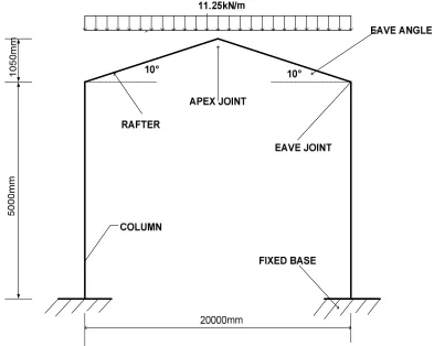
A steel frame shown in Fig. 2 was chosen as an example for this study. The frame forms part of arrangement of frames of an industrial building spaced at 5m centres. The roof imposed
LOADINGS AND MATERIAL PEOPERTIES
DIMENSIONS OF FRAME AND TARGET
SAFETY INDEX
CALL FORM TO COMPUTE SAFETY INDICES OF MEMBERS AND JOINTS
β≈βT
LIST FINAL SECTIONS OF FRAME MEMBERS AND JOINTS, AS WELL AS THE IMPLIED SAFETY INDICES
END DESIGN
OK!
ANALYSIS AND DESIGN OF FRAME MEMBERS
The frame was analyzed for forces and moments acting in its members and joints using elastic analysis. The steel and friction grip bolt used in the design are of grades grade S275 and 8.8 respectively, in accordance with the BS5950. Angle of inclination of the rafter-to-column
was considered to be 10o for the initial design, and later changed to 25o for the current analysis
based on earlier study [18].
The frame was thereafter designed in accordance with BS5950 [1] requirements. 533x210x109 UB satisfied the design conditions for both rafter and column. Eave and apex joints required 8No M20 and 6 No M20 bolts respectively.
4.2 Safety of the Deterministic Design of the Frame
The safety of the designed frame was checked using FORM [14] to be 11.0 and 7.42 when applied imposed load was assumed to be normally and gumbel distributed respectively.
Fig. 2: Frame Loaded with Ultimate Load.
4.2 Reliability-based Design of the Frame
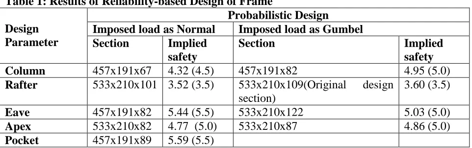
Table 1: Results of Reliability-based Design of Frame
Design Parameter
Probabilistic Design
Imposed load as Normal Imposed load as Gumbel
Section Implied
safety
Section Implied
safety
Column 457x191x67 4.32 (4.5) 457x191x82 4.95 (5.0)
Rafter 533x210x101 3.52 (3.5) 533x210x109(Original design
section)
3.60 (3.5)
Eave 457x191x82 5.44 (5.5) 533x210x122 5.03 (5.0)
Apex 533x210x82 4.77 (5.0) 533x210x87 4.86 (5.0)
Pocket 457x191x89 5.59 (5.5)
4.3 Discussion of Results
The results of the reliability-based design of the frame members presented in Table 1 are discussed as follows:
a) Comparison of the two design procedures
The implied safety indices of 11 and 7.42 in the deterministic design when imposed load was considered normal and gumbel respectively, are both the high side [16]. These values gave percentage increase of 120% and 48% above the recommended value. However, the results of the proposed procedure as presented in Table 1 are within the acceptable limit.
b) Effect of Imposed Load at constant target safety index
Considering the same target safety index, as the imposed load distribution was changed from normal to gumbel, the designed section increased (see Table 1). For instance,for the rafter member, there is an increase of 8% in weight due to resulting higher section. Also, the implied safety index increased because of the designed higher section adopted by the design. However, the corresponding percentage increase when apex joint was considered gave about 6% increase.
c) Effect of imposed load at varying target safety index
Considering the column design, when the TSI was changed from 4.5 to 5.0, there is a corresponding increase of 22% in weight. It is worthnoting to observe that a target safety of 5.5 considered for the eave joint which is slightly above the recommended threshold value [16], there is still increase in section size, which signifies that change in imposed loading.
d) Comparison of the design results of proposed procedures
Rafter design resulted in higher sections and is therefore considered the most critical, followed by the apex joint. This is as a result of the higher bending moment on the rafter than the apex joint. The pocket joint considered is the next in terms of safety because is a foundation joint (which was considered fixed) and experienced a high bending moment. Other members follow in terms of decreasing safety to be the eave joint and followed by the column. The eave joint as well transfers higher bending moment than the column.
5. CONCLUSION
of 120% and 48% respectively above the recommended threshold. Also, when the same TSI was considered, as the imposed loading was changed from normal to gumbel, there was increase in weight of 8% and 6% for rafter and apex joints respectively. Rafter design was also shown to be the most critical, followed by the apex joint, the pocket joint, the eave joint, and by the column.
6. REFERENCES:
1. BS5950, 2000. Structural use of steelwork, part 1. British Standards Institution, London
2. Nowak, A.S and Collins, K.R (2002) Reliability of Structures, Mc Graw Hill, Boston
3. Melchers, R.E., 1999. Structural reliability analysis and prediction. John Wiley and Sons,
New York.
4. Madsen, H.O., Addo, T. and Lind, N.C., 1999. Methods of structural safety. Prentice Hall
Press
5. Morris, L.J. and Plum, D.R., 1987. Steelwork design, volume 1. Section Properties -
Member Capacities, Steel Construction Institute.
6. http://www.en_wikepedia.org/wiki/Hyatt_regency_walkway_collapse (cited: 7/01/2008).
7. Abubakar, I. and Mohammed U.A., 2007. Reliability investigation of steel cased
columns. Australian Journal of Basic and Applied Sciences, Vol. 1, No. 4, pp 561 - 570.
8. Abubakar, I. and Musa, H.H. (2009). Reliability analysis of steel portal frames using
plastic method. Nigerian Journal of Engineering, Vol. 15, No. 2, pp. 1 - 7
9. Whitman, R.V., 1984. Evaluating calculated risk in geotechnical Engineering. Journal of
Geotechnical Engineering, American Society of Civil Engineers, Vol. 110, No. 2, pp 145 – 188.
10. Ellingwood, B., Galambos, T.V., MacGregor, J.G. and Cornell, C.A., 1980. Development
of probability-based load criterion for American national standard A58. Special Publication 577, National Bureau of Standards, Washington, pp 222
11. Sorensen, J.D., Hansen, S. O. and Nielsen, T. A., 2001. Calibration of partial safety
factors and target reliability level in Danish structural codes. Proceedings, IABSE
Conference on Safety, Risk and Reliability: Trends in Engineering, Malta, pp 1001-1006.
12. Tuner, R.C., Ellians, C.P. and Thomas, G.A.N., 1992. Towards the worldwide calibration
of API RP2A – LRFD. Conference Proceedings of 24th Offshore Technology 2:513– 520
13. Hasofer, A. M. and Lind, N. C., 1974. An exact and invariant first order reliability
format. Journal of Engineering Mechanics Division, ASCE, Vol., 100, No. 1, pp 111 - 121
14. Gollwitzer, S., Abdo, T. and Rackwiz, K., 1988. First order reliability method. Users
Manual, RCP-GMBH, Munich, West Germany
15. Thoft-Christensen, P. and Baker, M. J., 1982. Structural reliability theory and its
applications, Springer-Verlag, Germany, pp 82
16. JCCS, 2001 Probabilistic model code: parts 1 – 3, 12th Draft.
17. BS6399 (1996). Loading for buildings, Part 1 - Code of practice for dead and imposed
loads, British Standards Institution, London
18. Abubakar, I. and Abdulkadir, O.I. (2011). Efficient eave angle of a rigid steel pitched
portal frame using reliability concepts, 1st interquadrennial ICF conference in Africa and