© 2018 IJSRST | Volume 4 | Issue 2 | Print ISSN: 2395-6011 | Online ISSN: 2395-602X Themed Section: Science and Technology
Fuzzypi DTC Scheme Based On SVM for Sensorless Induction Motor Drive
D.Sushmitha Priyadarshini1, J. N. Chandra Sekhar2M.Tech Scholar1, Assistant Professor2
E.E.E Department, S.V University College of Engineering, Tirupati, Andhra Pradesh, India
ABSTRACT
This paper describes a mix of direct torque control (DTC) and space vector modulation (SVM) for a customizable speed sensorless induction motor (IM) drive. The motor drive is provided by a two-level SVPWM inverter. The inverter reference voltage is gotten in view of information output criticism linearization control, utilizing the IM display in the stator – axes reference frame with stator current furthermore, transition vectors segments as state factors. Additionally, a powerful full-arrange versatile stator transition observer is intended for a speed sensorless DTC-SVM system and another speed-versatile law is given. By outlining the observer pick up matrix in view of state criticism control hypothesis, the strength and robustness of the observer systems is guaranteed. At last, the viability and validity of the proposed control approach is verified by simulation results.
Keywords : direct torque control (DTC), space vector modulation (SVM), induction motor (IM).
I.
INTRODUCTION
DIRECT TORQUE CONTROL (DTC) abandonsthe stator current control theory, normal for field oriented control (FOC) and accomplishes bangbang torque and motion control by straightforwardly altering the stator voltage in agreement with the torque and transition errors. Along these lines, it shows a decent following for both electromagnetic torque and stator motion [1]. DTC is described by quick unique reaction, basic straightforwardness, what's more, solid power despite parameter vulnerabilities and perbutations.
One of the inconveniences of ordinary DTC is high torque ripple [2]. A few strategies have been produced to decrease the torque ripple. One of them is obligation proportion control strategy. In obligation proportion control, a chose output voltage vector is connected for a segment of one testing period, and a zero voltage vector is connected for whatever remains of the period. The pulse length of output
DTC-SVM system what's more, a speed-versatile law is given. The spectator pick up matrix, which is gotten by fathoming straight matrix imbalance, can make strides the vigor of the versatile observer pick up in [7]. The steadiness of the speed versatile stator transition spectator is additionally ensured by the pick up matrix in low speed. The proposed control calculations are confirmed by broad extensive simulation results.
II.
DTC-SVM BASED ON INPUT-OUTPUT
LINEARIZATION
A. Model of Induction Motor
Under supposition of linearity of the magnetic circuit dismissing the iron misfortune, a three-stage IM show in a stationary axes reference with stator currents and motion are expected as state factors, is communicated by
̇ ( )
(1)
̇ ( )
(2)
̇ (3)
̇ (4)
where , , , , are respectively theD –Q axesof the stator flux, stator voltage and stator current vector components,is the rotor electrical angular speed, , , are the stator, rotor, and magnetizing
inductances, respectively, ( )and are
the stator and rotor resistances,respectively.
The electromagnetic torque in the induction motor can beexpressed as
(5)
where is the number of pole pairs.
B. DTC-SVM Based on Input-Output Linearization The DTC-SVM scheme is developed based on the IM torqueand the square of stator flux modulus as the system outputs;
stator voltage components defined as system control inputs andstator currents as measurable state variables.
Let the system output be
(6)
| | = (7)
Define the controller objectives and as
(8)
| | | (9)
where , are reference value of electromagnetic torqueand stator flux, respectively.
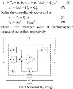
Fig. 1.Standard design.
According to (1)–(5), the time derivative of is as (10)
[ ̇̇] * + [ ] (10)
where
( ) m( ( )
|
Rs( )
D=[
]
C=-( )
According to , the characteristicdeterminant of is as follows:
det(D)=-
| | (11)
From (11), is D a nonsingular matrix since the inner productof stator flux vector and rotor flux vector can not be physicallyzero.
Based on input-output feedback linearization [8], the followingcontrol inputs are introduced:
where , are the auxiliary control inputs and are definedbased on the pole placement concept of the linear control systemsso that
(13) where and are positive constants.
III.
PEED ADAPTIVE STATOR FLUX OBSERVER
A. Speed Adaptive Stator Flux Observer
Using the IM model of (1)–(4), the speed adaptive stator fluxobserver is introduced:
̇
Where
x=( ,u=( , ,
B=*
+
T,C=[I 0], I=*
+, J=*
+
,
A=A0+ AR+ Aw
= [
] + [
] +
[ ]
the uncertain parameters in matrixAare part in two sections; one relating to apparent or steady operation and the second to obscure conduct. what's
more, are apparent estimation of stator protection and rotor protection, and are stator protection what's more, rotor protection vulnerabilities, separately.
The state observer, which estimate the state current and the stator motion together, is given by the accompanying condition
̂
̂RA )+Bu+H( ̂s-is) (15)
wherê ̂ ̂ ̂ ̂ Tare evaluated estimations of the state variable and H is the spectator pick up matrix. Assuming state mistake ise, i.ee=̂
(e)=
(̂
( )
=(A0+HC+ RA )e+ rA ̂ (16) With a specific end goal to determine the versatile plan, Lyapunov hypothesis is used. Presently, let us characterize the accompanying Lyapunov work:
V=eTe+( ̂ r)2/𝝀 (17)
The time subordinate of V is as per the following:
e[(A0+HC+ RA )
T]+(A0+HC+
rA )e+ r (̂T eTA ̂)+ ( ̂ r) ̂
(18) Let
r(̂T eTA ̂)+ ( ̂ r) ̂
=0 (19)
in the event that we select observer pick up system with the goal that the validity of the disparity
eT[(A0+HC+ RA )T]+(A0+HC+ rA )e
(20)
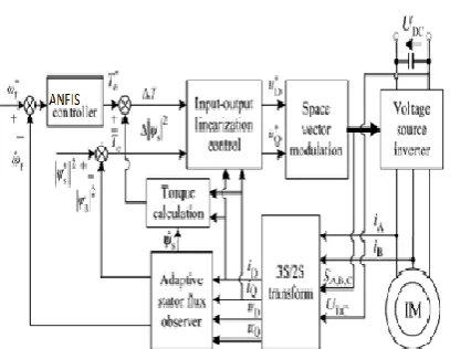
Fig. 2.The block diagram of the existing DTC-SVM system.
ANFIS Controller: An adaptive neuro-fuzzy inference system or adaptive network-based fuzzy inference system (ANFIS) is a kind of artificial neural
network that is based on Takagi–Sugeno
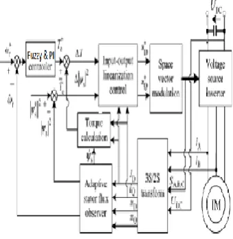
Fig 3 :The block diagram of the Proposed DTC-SVM system.
Fig 3: The network of ANFIS controller
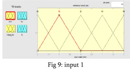
Fig 4: Membership functions for error and change in error.
Fig 5 :The block diagram of the Proposed DTC-SVM system.
Fig 6:Input 1
Fig 7 :Input 2
Fig 8:Output TABLE I ANFIS RULES
S N L N M N S N S N Z E S P M P Z E L N M N S N Z E S P M P L P S P M N S N Z E S P S P M P L P M P S N Z E S P M P M P M P L P L P Z E S P S P M P L P L P L P
can be ensured, the state observer is steady. The versatile plan for speed estimation is given by
̂ ( ) ̂
B. Observer Gain Matrix Computation
Let’s introduce a theorem about quadratic solidness of vulnerability system before plan the observer pick up matrix.
Lemma: Uncertainty system
̇ ( ) (22)
is quadratic stable, if and just if is steady and
‖ ‖ (23)
where is apparent network, which should be well known, is represents to the vulnerabilities on due to unmodeled conduct or parameter float, and are the vulnerability structure networks of the system, is vulnerability coefficient.
On the off chance that is additionally composed as , so system (16) is quadratic stable, if and just if is steady and
‖ ‖
Assuming ,K=HC quadratic steadiness issue of system (16) can be changed to static state criticism control
issue for the system as Fig. 1.
A state-space acknowledgment of Fig. 1 is as (25)
G(s)=[
](25)
As system (25), there will be a state criticism controller , if and just if there are certain clear network and to
make straight matrix imbalance (26) is fulfilled
[
] (26)
In the * and W* event that and is a doable answer for direct systemdisparity (26), at that point u=W* ( *)
-1xis a state criticism controller H of system (25). In
this way, K=W* ( *)-1 . The spectator pick up matrix can be acquired from H=KC-1.
TABLE II PARAMETERS OF IM
R a t e d p o w e r P ( k W ) 3 R a t e d v o l t a g e U s ( V ) 3 8 0 R a t e d c u r r e n t I s ( A ) 6 . 8
Rated frequency f(Hz) 5 0
Magnetic pole pairs pn 2 R at ed s pe ed n( r/ m in ) 1 4 2 0 Stator inductance Ls(H) 0 . 0 8 6 Rotor inductance Lr(H) 0 . 0 8 6 Mutual inductance Lm(H) 0 . 2 4 3 Stator resistance Rs( 1 . 6 3 5 Rotor resistance Rr( ) 1 . 9 Statorflux linkage (Wb) 0 . 8
Extension
Fuzzy PI Controller:
Fuzzy logic is a form of many-valued logic in which the truth values of variables may be any real number between 0 and 1. By contrast, in Boolean logic, the truth values of variables may only be 0 or 1. Fuzzy logic has been extended to handle the concept of partial truth, where the truth value may range between completely true and completely false. Furthermore, when linguistic variables are used, these degrees may be managed by specific functions.
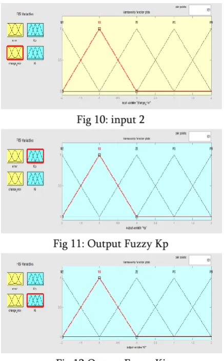
Fig 10: input 2
Fig 11: Output Fuzzy Kp
Fig 12:Output Fuzzy Ki
TABLE III FUZZY PI RULES
c / c e N B N S Z E P S P B
N B Z E PB,NS PB,NB PB,NS Z E
N S P S PB,ZE PS,NS ZE,ZE P S
Z E P B PB,PS ZE,ZE PB,PS P B
P S P S ZE,ZE PS,NS PB,ZE P S
P B Z E PB,NS PB,NB PB,NS Z E
TABLE IV
COMPARISON OF RIPPLE and THD FOR CONTROLLERS
PARAMETER ANFIS(%) FUZZYPI(%)
TORQUE 2.4 1.48
CURRENT 4.37 3.13
V. SIMULATION RESULTS
Fig. 13.Torque response curve of Proposed and Extension.
Fig. 14.Speed response curve of Proposed and Extension.
Fig. 15. D-axes stator flux curve.
Fig. 16. Q-axes stator flux curve.
0 0.1 0.2 0.3 0.4 0.5 0.6 0.7 0.8 0.9 1
-5 -4 -3 -2 -1 0 1 2 3 4 5 time to rq u e anfis fuzzy-pi
0 0.1 0.2 0.3 0.4 0.5 0.6 0.7 0.8 0.9 1
-50 0 50 100 time sp e e d anfis fuzzy-pi
0 0.1 0.2 0.3 0.4 0.5 0.6 0.7 0.8 0.9 1
-2 -1.5 -1 -0.5 0 0.5 1 1.5 2 time st a to r d a xi s fl u x( w b ) anfis fuzzy-pi
0 0.1 0.2 0.3 0.4 0.5 0.6 0.7 0.8 0.9 1
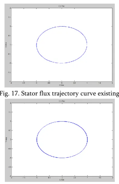
Fig. 17. Stator flux trajectory curve existing
Fig. 18. Stator flux trajectory curve Proposed.
IV.
CONCLUSION
A novel DTC-SVM plot has been produced for the IM drive system, which is on the premise of info output linearization control. In this control strategy, a SVPWM inverter is utilized to bolster the engine, the stator voltage vector is gotten to completely adjust the stator motion and torque errors. Besides, a robust full-arrange versatile motion spectator is intended for a speed sensorless DTC-SVM system. The stator motion and speed are evaluated synchronously. By planning the consistent observer pick up network in light of state criticism control hypothesis, the heartiness and soundness of the observer systems is guaranteed. Accordingly, the proposed sensorless drive system is able to do consistently working in low speed, has significantly littler torque ripple and shows great dynamic and enduring state execution.
In future replacing FUZZY-PIcontroller withANFIS-PI will give better performance of the system.
V.
REFERENCES
[1]. I. Takahashi and T. Noguchi, “A new quick-response
and high efficiency control strategy of an induction motor,” IEEE Trans. Ind. Appl., vol. IA-22, no. 5, pp. 820-827, 1986.
[2]. Y. S. Lai and J. H. Chen, “A new approach to direct
torque control of induction motor drives for constant inverter switching frequency and torque ripple reduction,” IEEE Trans. Energy Convers., vol. 16, no. 3, pp. 220-227, 2001.
[3]. S. Mir, M. E. Elbuluk, and D. S. Zinger, “PI and
fuzzy estimators for tuning the stator resistance in direct torque control of induction machines,” IEEE Trans. Power Electron., vol. 13, no. 2, pp. 279-287, 1998.
[4]. F. Bacha, R. Dhifaoui, and H. Buyse, “Real-time
implementation of direct torque control of an induction machine by fuzzy logic controller,” in Proc. ICEMS, 2001, vol. 2, pp. 1244-1249.
[5]. A. Arias, J. L. Romeral, and E. Aldabas, “Fuzzy
logic direct torque control,” in Proc. IEEE ISIE, 2000, vol. 1, pp. 253-258.
[6]. D. Seyoum, M. F. Rahman, and C. Grantham,
“Simplified flux estimation for control application in induction machines,” in IEMDC’03, 2003, vol. 2, pp. 691-695.
[7]. G. Xi, H. Gao, and W. Xuet al., “A method to
determine gain matrix of stator flux full order observer,” J. Cent. South Univ. (Science and Technology), vol. 39, no. 4, pp. 793-798, 2008.
[8]. J. Soltani1, G. R. A. Markadeh, and N. R. Abjadi3 et
al., “A new adaptive direct torque control (DTC) scheme based-on SVM for adjustable speed sensorless induction motor drive,” in ICEMS 2007, Seoul, Korea, Oct. 8-11, 2007, pp. 49-502.
[9]. C. Xia, Z. Li, and T. Shi, “A control strategy for
fourswitchthree phase brushless dc motor using singlecurrent sensor,” IEEE Trans. Ind. Electron., vol. 56,no. 6, pp. 2058-2066, Jun. 2009.
[10]. T.-S. Kim, B.-G.Park, D.-M.Lee, J.-S.Ryu, and D.-S.
Hyun, “A new approach to sensorless controlmethod for brushless DC motors,” Int. J. Control,Autom. Syst., vol. 6, no. 4, pp. 477-487, Aug. 2008.
[11]. P. Damodharan and K. Vasudevan, “Sensorless
brushless DC motor drive based on the
zerocrossingdetection of back electromotive
force(EMF) from the line voltage difference,” IEEE Trans. Energy conv., vol. 25, no. 3, pp. 661-668,Sep. 2010.
[12]. S. B. Ozturk and H. A. Toliyat, “Direct torque
motor,”IEEE/ASME Trans. Mechatronics, vol. 16, no. 2, pp. 351-360, Apr. 2011.
[13]. Byoung-Kuk Lee, Tae-Hyung Kim and M.
Ehsani,“On the feasibility of four-switch three-phase BLDCmotor drives for low cost commercial applicationstopology and control” IEEE Trans. Power Electron.,vol. 18, no. 1, pp. 164-178, 2003.
[14]. Hsiu-Ping Wang and Yen-Tsan Liu,
“Integrateddesign of speed-sensorless and adaptive speedcontroller for a brushless DC motor,” IEEE Trans. Power Electron., vol. 21, no. 2, pp. 518-523, 2006.
[15]. C. S. Joice, S. R. Paranjothi and V. J. S. Kumar,