STUDY OF DESIGNING, MANUFACTURING AND
TESTING OF MULTI-SLIDE PRESS TOOL FOR
ARCH-CHUTE COMPONENT
Tejas Mogal
1, Vivek Baviskar
2, Rupesh Borase
3, Hannan Deshmukh
4,
Pankaj Patil
5, Chandrashekhar Patil
61,2,3,4
B.E.Mechanical, Pune University, (India)
5,
Assistant Professor,
6Principal BVCOE& RI Nashik (India)
ABSTRACT
The press tool life is major criteria in high volume production of sheet metal components. For a Progressive die, proper tool life and component accuracy are necessity for achieving higher productivity and low cost per component. In this project we are going to form a basis by accumulating factors for tool life selection and making data easily available for industrial designers. The data is based on old tool which was analyzed and its characteristics were studied closely and improvements were made which is a part of our project. In this work, we will use the designing software for modifying a progressive tool for Arc Chute plate. Here, a multiple station dies with initial operation as Trimming and later as parting off is performed. In each stroke, one operation is performed with four punches, thus in one stroke we get four final plates. The main aim of our project is to manufacture large number of components in less time. The press tool in this project will have a very short stoke. After making the press tool we will inspect the component and then finalize the tool for production. We will also record the data for cost estimation. Thus, factor selection is made easy by specific data made available and the usefulness of the system is demonstrated by sample run of Arc Chute plate analysis. It caters for obtaining the final components conforming to required dimensions and standards.
Keywords: Press tool, Tool life, Arc chute plate, Progressive die.
I. INTRODUCTION
A multi-slide press tool can perform many operations compared to other dies and also it can able to eliminate
the loading & unloading time which results in faster production rate. Multi-slide press tool is a kind of
assembled die where in more than one operation can be done at a time. This multi-slide press tool is applicable
mainly on sheet metal operations, where in all the tools are previously loaded in a sequence as per the operation
requirements. Multi-slide press tool perform a series of fundamental cutting and forming operations typically on
continuous sheet metal strip, or coil, stock. These operations are performed simultaneously at two or more
stations during each press stroke as the strip progresses through the die to produce a part. Positioning of the
stock at each station is accomplished by pilot holes or slots. As the stock advances through the die stations,
unwanted material is cut out leaving one or more tabs, ribbons, or bridges to connect the partially completed
operations within a single multi-slide press tool arrangement, significant cost savings are realized especially on
high volume production runs. Multi-slide press tools for producing sheet metal parts in mass production have
been widely applied in various industries such as aerospace, electronics, machine tools, automobiles, and
refrigeration. These dies can perform piercing, notching, cut-off, blanking, lancing, bending, shaving, drawing,
embossing, coining, trimming, and other miscellaneous forming operations at a single setup. Hence a
multi-slide press tool is generally very complex. Stamping process planning and die structure design are difficult and
demanding tasks. The productivity, accuracy, cost, and quality of a multi-slide press tool mainly depends on the
strip layout, and hence a stamping process. The diverse knowledge sources (KS’s) related to stamping process
planning include unfolding knowledge to produce a flat pattern, nesting knowledge to produce a blank layout,
various types of planning knowledge for different stamping operations like piloting, piercing, notching, cut-off,
blanking, bending, etc., and staging knowledge to sequence the stamping operations. A discussion of some
knowledge based multi-slide press tool design work related to our study can be found in the next section.
However, the existing work is based on the conventional architecture of knowledge based expert systems, which
are incapable of managing heterogeneous KS’s effectively. In addition, this work doesn't provide a
representation scheme for experts to model their valuable, but difficult-to-articulate, knowledge in terms with
which they are familiar.
1.1 Problem Statement
We have to make press tool which will cater the requirement of a press tool having high tool life and to obtain
mass production. We offered from a choice of manufacturing a new tool with improved characteristics. The
company wants to design a press tool for a multipurpose press machine.
1.2 Objective
The main objective is to manufacture a multi-slide press tool with high tool life with good productivity. For this
we have to design a press tool to carry out various operations for archute component. We will have to study the
press machine, their functions and the limitations for the design. We need to provide effective utilization of
material by selecting most feasible strip layout. We will focus on reducing stroke length for effective utilization
of cutting forces. High precision component can be obtained. The tool life is also very high. The tool life is 2
Crore parts.
II. LITERATURE REVIEW
Authors: Vishwanath M.C., Dr. Ramni, Sampath Kumar et al. [1]
The above authors have done a research on this topic before. They have done the research from a very basic
level. They have noted down very important points regarding the designing and manufacturing of multi-slide
press tool. They have concluded the following:- “By the implementation of computer in design field accuracy of
design is improved and design field accuracy of design is improved and design process time is reduced
drastically than by traditional method. In the process of creating the documentation for the product design much
of required data base to manufacture the product is also created. Many design problems which are complicated
to estimate by traditional methods are eliminated by using CAD system. As the designs have more
reduce prototype testing regarding progressive die design of progressive die is simple. Advantage of progressive
die is it performs two or more operations simultaneously by a single stroke. Progressive die is used for high rate
of production this design procedure can also be extended for manufacturing washers for M-series bolts by
modifying the punches and die plate dimension.”
2.1 About Multi-Slide Press
The simplest way to describe a multi-slide, 4 slides or four-way is a horizontal stamping press that uses cams to
controls tools. The key difference is instead of an “up and down” motion like in a punch press, the multi-slide
machine works on right angles. Its moving slides that have tools attached, which strike the work piece to form
it.These slides are driven by four shafts that outline the machine. The shafts are connected by bevel gears so that
one shaft is driven by an electric motor, and then that shaft’s motion drives the other three shafts. Each shaft
then has cams which drive the slides. This shafting arrangement allows the part to be worked for four sides,
which makes this machine extremely versatile. A hole near the center of the machine is provided to expel the
completed work piece.Examples of multi-slide parts we produce are flat springs, spring clips, brackets, collars,
limiters, shunts, shims, connectors, friction plates, retainers, and terminals. They are basically the same
machine. A multi-slide simply has a bigger bed size than a four slide. CAR Engineering has 12 multi-slides and
one four-slide. Shown below is a video of the actual Multi-Slide and Four-Slide stamping presses from our
factory: Because the die in a multi-slide works on right angels and can “attack” the work piece from many
directions, the die is often more complex than a progressive die built for a punch press.
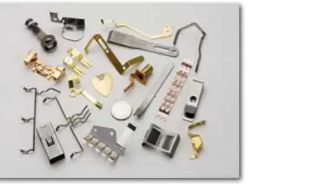
Fig No. 1: Components manufactured from Multi-Slide Press Process
A number of material-intensive parts can be produced as four slide metal stampings: balance clamps, base
weights, brackets, brake flanges, bushing seats, conveyor flights, engine bases, flywheel shrouds, framed
hangers, friction plates, gear and sprocket blanks, lock tabs, reinforcement plates, retainers, spring seats, upright
bars, wear and swivel pads, wheel or backing rings and yoke guides. Stamping services use punches and dies to
create three-dimensional parts and add surface definition such as lettering to flat-sheet materials. They can
process ferrous and nonferrous metals, exotic metals and alloys, precious metals, and thermoplastic materials.
Stamping services differ in terms of capabilities and may use deep drawing, fine blanking, multi-slide stamping,
or progressive die techniques. Deep drawing uses a punch to fabricate deeply-recessed parts. The depth of a
deep-drawn part exceeds its width, as with a cup made from a flat metal sheet. Fine blanking is a specialized,
high-precision blanking technique in which material is sheared smoothly through its entire thickness. Fine
Multi-slide or multi-slide stamping incorporates the vertical motion of a punch with horizontal die applications
from multiple directions, either simultaneously or successively. Progressive dies are used in production-efficient
processes where multiple stamping operations are performed in successive stages or positions along the
fabrication cycle.
2.2 About Multi-Slide Press Machine
The machine we are going to use for press operation is Germany made machine. Its name is Bihler. The
machine’s name is GRM 80E. It’s a high volume manufacture of small stamped components from strip stock. It
is a horizontal stamping press that uses cams to control tools. It has the ability to complete all of the operations
required to form the work piece from start to finish. Due to this flexibility it reduces the cost of the finished part
because it requires less machines, setups, and handling.
The main parts of the machine are motor, clutch, pneumatic system, hydraulic system and central lubrication.
These parts form the housing of the machine. The forming unit includes straightener, presses and slides. The
operations which can be done are blanking, bending, mounting, riveting and welding. Also complimentary
operations include screw insertion, mounting, threading and evaluation.
III. SPECIFICATIONS OF THE MACHINE
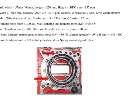
Strip width = 55mm / 60mm, Length = 220 mm, Height in BDC mm = 157 mm
Width = 168.5 mm, Machine speed = 5- 250 s.p.m, Material dimensions = Max. Strip width 80 mm; Max. Wire diameter 6 mm, Stroke rate = 5 – 250 (1/ min) Stroke = 12 mm
Nominal press force = 300 kN, Max. Bending unit nominal force (KN) = 90 KN Feed length to (mm) = 500 , Strip width; width increase to (mm) = 80 mm
Central Mandrel (stroke mm, nominal force KN) = 80 /35 ,Center aperture = (W x H mm) = 644 / 200 Axis- head positions = 32 Central gearwheel drive Spring mounted guide plate.
Fig No. 2: Central Gear Wheel in the Machine
In machines with central gearwheel, the energy is transferred to central gearwheel via worm shaft and idler gear
from clutch/ brake combination. The gears on the corresponding forming unit mesh directly with the central
gearwheel through the mounting bores. The front tool finish forms the front portion of the stamping, as well as
tools can simultaneously advance to impart another 90 degree bending of the ends inward around the mandrels.
Then the back tool advances to finish form the ends of the stamping around the mandrels. At this point, the tool
slides retract. The stripper rod is attached to the stripper rod to push the formed stamping from the mandrel
through an opening in the bed of the machine into a container .The same basic knowledge that the tool and die
maker and the tool designer have for tooling a punch press is sufficient for tooling the multi-slide. In fact, the
problems of building tooling are usually simple but perceptive skills are needed. Our next installment will
discuss why it’s better to make a music wire spring on a multi-slide instead of using a punch press. Many
formed stampings, whether made of strip or wire, whether completed parts or just components can be produced
by a multi-slide as well as on a punch press. But if the job can be made on either of the machines, it is necessary
to know the capabilities of each in order to choose which can do the job most efficiently and economically.
Today, increasing competition and a shortage of skilled labor have combined to put pressure on tool and die
makers, tool designers, and plant engineers to produce parts faster and cheaper, and at the same time save on
material.And that’s where the multi-slide comes in. Trouble is, even though this machine has been around for
some 80 years, few shops know how to use it effectively. Admittedly, there are a number of knowledgeable job
shops that use multi-slides, but most other plants don’t seem to realize that they can produce complex parts on a
multi-slide with simple tooling at low cost, and on a short lead time. Over the years, the multi-slide has become
a one-machine automated production line: raw stock is fed into it, and a completed part emerges with each
stroke. It has a certain edge over the punch press in such operations as matching to bending, but that is not to say
that generally the punch press is just as efficient as the multi-slide when correctly tooled for a selected part.
Because of the multi-slide’s versatility, the tooling designer is able to develop simple tooling for formed parts,
whether they’re made of strip or of wire. Certainly, a music wire formed part would be a tough job for a punch press. But it’s a breeze for the multi-slide.
Many job shops today have a wide range of multi-slides, so as to give them a choice that is dictated by the size
of the part to be made and the tonnage required. In all multi-slide models, however, basic operations are the
same: a slide feed pulls the material off a stock reel, through a straightener, and into the press head area. After
the piece is punched, or goes through other stamping operations, it travels into the multi-slide’s forming area,
where it is parted and formed into shape by developed tool blocks that are arranged to suit conditions. And the
positive feed is accurate in most cases within +- 0.002 in. In some cases, tolerances can be held within +- 0.001
in. The tools in the four slides can be adjusted in any direction, while the tools of a progressive die cannot be
cross adjusted. This also allows flexibility in any necessary deviations from design specifications after the tools
are made. Such corrections in a die might be impossible. Another quality and production consideration is that
buckling of stock can be a serious problem with progressive dies. This can affect quality or cause undesirable
machine downtime. Because forming takes place after the stamping operations buckling is reduced. Material
cost, especially with strip stock, is usually lower with the multi-slide. Because of the operating characteristics of
the punch press, many times pilots are needed to insure accurate feeding and this means extra stock for pilot
holes. Or again, added stock width might be necessary to prevent buckling. Then, to allow for possible
variations in feed lengths in the punch press, material is provided between blanking in the strip. With the close
tolerance control on feeding in the multi-slide and because feed length usually equals blank length, less strip is
for the same part. NOT TRUE, multi-slide tooling is significantly lower. Again, it is good to remember that one
big advantage of the multi-slide is that it can form complex shaped parts completely in one machine without
secondary handling. As was mentioned earlier, the tool life usually is longer in the multi-slide, so the number of
final parts required affects the tool cost, too. Even if the multi-slide tooling cost 24% more initially than a
progressive die. But the die life is half that of the multi-slide tools. Then the actual tool cost for the progressive
die is 60% higher than the multi-slide tooling.
Other economies are realized because of the greater flexibility of the multi-slide machines. Hourly production
can be doubled in some cases by manufacturing two parts simultaneously. Or, complex parts can be partially
formed at the same level as the die, and then stripped to a lower level where a second set of tooling completes
the forming operations. At other times, a third level and set of tools may be used again to complete the form in
one machine without secondary operations. So many factors must be considered in determining which process is
best. The modern stamping plant uses both kinds of machines for best results.
The multi-slide has far more potential as a cost saver than has been indicated so far in this series of articles.
Most people don’t set up more than single level operations with a combination of one or more of the four
forming slides. But this same machine can increase its output substantially with multiples of four operations in
the forming section. Thus stampings requiring four, eight, or twelve forming steps can be produced at no more
cost than if the operation were limited to four forming steps. The trick here is to partially form the stamped part
at one level, than strip it down to a lower level, where final forming is done with additional tools. These dual
level tooling’s is known as multiple block tool design. Stacked tool blocks, for example, are fastened together,
and move together. The top tool performs part of the initial forming sequence, whereas the lower tool is the
finisher. Multiple tool blocks, however, aren’t necessary for each slide, because tools are designed according to
the requirements at each station.
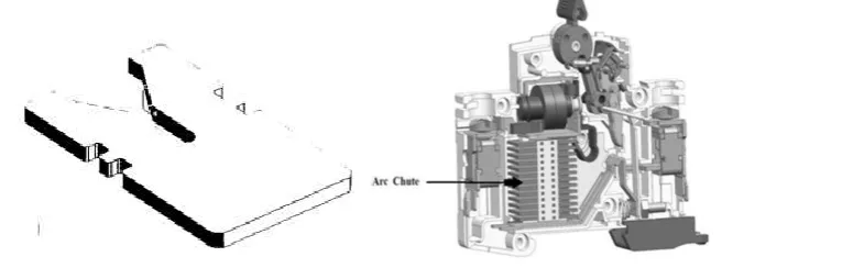
3.1 About Arch-Chute Component
The arc runner and arc chute limit and dissipate the arc energy during the interruption of an overload or short
circuit event. During an overload or short circuit event, the contacts of the breaker separate and an electrical arc
is formed between the contacts through air. The arc is moved into the arch chute by “running” the arc down the
interior of the breaker along the arc runner. When the arc reaches the arc chute it is broken into small segmented
arcs. The segmented arcs split the overall energy level into segments less than 25V. Each 25V segment does not
have a high enough energy level to maintain an arc and all energy is naturally dissipated.
Low-voltage MCB (Miniature Circuit Breaker) uses air alone to extinguish the arc. These circuit breakers
contain so-called arc chutes, a stack of mutually insulated parallel metal plates which divide and cool the arc. By
splitting the arc into smaller arcs the arc is cooled down while the arc voltage is increased and serves as
additional impedance which limits the current through the circuit breaker. The current-carrying parts near the
contacts provide easy deflection of the arc into the arc chutes by a magnetic force of a current path,
although Magnetic blowout coils or permanent magnets could also deflect the arc into the arc chute (used on
circuit breakers for higher ratings). The number of plates in the arc chute is dependent on the short-circuit rating
and nominal voltage of the circuit breaker. In larger ratings, oil circuit breakers rely upon vaporization of some
of the oil to blast a jet of oil through the arc. Gas (usually sulfur hexafluoride) circuit breakers sometimes stretch
the arc using a magnetic field, and then rely upon the dielectric strength of the sulfur hexafluoride (SF6) to
quench the stretched arc. Vacuum circuit breakers have minimal arcing (as there is nothing to ionize other than
the contact material), so the arc quenches when it is stretched a very small amount (less than 2–3 mm (0.079–
0.118 in)). Vacuum circuit breakers are frequently used in modern medium-voltage switchgear to 38,000 volts.
Air circuit breakers may use compressed air to blow out the arc, or alternatively, the contacts are rapidly swung
into a small sealed chamber, the escaping of the displaced air thus blowing out the arc. Circuit breakers are
usually able to terminate all current very quickly: typically the arc is extinguished between 30ms and 150ms
after the mechanism has been tripped, depending upon age and construction of the device. The maximum
current value and let-through energy determine the quality of the circuit breakers.
3.2 Advantages & Disadvantages
Typically a multi-slide tool takes longer to set up than a punch press tool. The multi-slide tooling is often more
complex than punch press making the lead time to design, build, and debug a multi-slide tool a little longer,
typically 2-3 weeks of additional development. There are many cost-effective reasons to consider a multi-slide
versus a more traditional production method. Often material usage can be reduced dramatically by
manufacturing parts with a multi-slide. With a punch press, material is needed on either side of the strip in order
to carry the part through the die. However with a multi-slide the material can be purchased slit to width, less
material means less cost per work piece. It is especially important to consider a multi-slide stamping when the
part is made out of expensive red metals such as copper or brass. The various motions provided by the die head,
such as forming slides, vertical stripper mechanisms, and a range of auxiliary units, afford the DFM engineers at
shop nearly limitless opportunities for tool and die manufacturing of stampings at considerably lower part
cost-per-piece by eliminating secondary operations and handling. Because of their versatility, our multi-slides can be
modified for simultaneous feeding and processing of multiple strips to complete an assembly.
In addition, prefabricated parts can be hopped, positioned, and fed for automated assembly as part the
production metal forming process. A four-slide can tap without having to purchase expensive in-die tapping
equipment or needing a secondary process. Our journeyman tool and die makers are the best in the industry.
Because the die in a multi-slide works on right angels and can “attack” the work piece from many directions, the
IV. CONCLUSION
By introducing progressive die for Arc Chute Plate, it is concluded that the tool is very feasible for the medium
batch capacity and efficient in operation. By using two stage tool die, the tool life is 3 -12 lac components. Also,
the accuracy of the component is high due to use of precision machine for production of the punch and die. The
provision for replaceable inserts has made the maintenance simple. It is, thus, concluded that the productivity of
any firm is directly proportional to its profit.
REFERENCES
[1] Vishwanath M.C., Dr. Ramni and Sampath Kumar L., “Design of Progressive Draw tool”, International
Journal of Scientific and Research Publications, Volume 3, 2013.
[2] Kumar Shailendra, “An Intelligent system for selection of Materials for press tool components”, Journal of
Engineering Research and Studies, S. V. National Institute of Technology, Surat, India, 2011
[3] Pawan Kumar Rai, Dr. Aas Mohammad, Hasan Zakir Jafri, “Causes and Prevention of Defects (Burr) In
Sheet Metal Component”, International Journal of Engineering Research and Applications (IJERA), 2013.
[4] Dr. Sotiris L Omirou, “Manufacturing processes”, SAE Tech. Paper, J.Jpn plast, Japan, 2006.
[5] D. Eugene Ostergaard, “Basic Die Making”, McGraw-Hill book company, New York
[6] Herman Jutz and Eduard Scharkus, Westerman tables, New Age International (P) Limited Publishers, 3rd
edition, New Delhi, 2004
[7] DTC, “Master file for Press Tool technology”, NTTF, Bangalore, October 2002
[8] D. Eugene Ostergaard, “Basic Die Making”, McGraw-Hill book company, New York
[9] Tool Design Data Book, Directorate of Technical education, Govt. of Tamil Nadu, Chennai-25