SEISMIC ANALYSIS OF STEEL FRAMES WITH
ECCENTRIC BRACINGS USING PUSHOVER
ANALYSIS
Mohd Mubeen
1, Khalid Nayaz Khan
2, Mohammed Idrees Khan
3 1Post Graduate Student, Structural Engineering,
2Associate Professor,
3Assistant Professor
1,2,3
Department of Civil Engineering, Ghousia College of Engineering, Ramanagaram (India)
ABSTRACT
In this thesis, the nonlinear pushover analysis is carried out for high rise steel frame building with different patterns
of eccentric bracing systems. There are n‟ numbers of possibilities to arrange Steel bracings such as Diagonal, X, K,
and V, Chevron type eccentric bracings. A typical 10-story steel frame building is analysed for various types of
eccentric bracings like Diagonal, V, Chevron or Inverted V and Performance of each frame is carried out through
nonlinear static analysis.Mode shapes, Storey drift, Base shear, Pushover curve and Performance point of each
model are carried out with different type of eccentric bracing systems. Three types of steel sections i.e., ISHB, ISMB,
and ISA are used for the comparison, for the same pattern of eccentric bracings.The Aim of this study was to compare
the results of seismic analysis for high rise steel frame building with various patterns of eccentric bracings. The
software used for this study was ETABS 2013.
Keywords: Base Shear, Eccentric Bracing System, Mode Shapes, Non-Linear Static Analysis, Performance Point,
Pushover Analysis, Steel Frames
I. INTRODUCTION
Earthquake is an oscillation which is generated by forces beneath the lithosphere, moving through the atenosphere. It can be stated as the vibration which takes place because of energy released in atenosphere. The energy release is caused by immediate disruption of portion of the crust, demonstrative outburst, or even explosions created by humans.
Every year, countless people die as a result of earthquake all over the world. Lateral strength is an important problem for steel structures especially in regions of seismic zones. The earthquake in Japan by name Kobe and in the USA by name Northridge were two clear illustrations where we came to know that there was absence of lateral stability in structures constructed using steel. This problem has been a significant subject of consideration for investigators. Finally researchers gave an effective idea of using bracing systems like concentric, eccentric and knee bracing systems. The bracing system provides the structure more capacity to soak up energy while it is under seismic excitation.
mentioned systems are intended to resist a major earthquake within the elastic limit of the materials and will require post-earthquake repairs.
Steel is an important construction material and plays a very significant role in the developing societies. Construction is an industry where steel is used to a greater extent, exceeding use of 50% of world’s steel. Structures such as home, parking lots, gardens, educational institutes, and high rise framed buildings- rely mostly on steel for their ductility and strength. Steel also offers good architectural view and it gives more freedom of design for structural engineers. Steel gives freedom for shape and maximum space of an area to be built with use of steel. The grouping of strength, ductility, attractiveness, preciseness and ductility permits architects wider possibilities to analyse enormous interpretation and establish various solutions.
As seismic excitations are erratic in terms of extent, occurrence, period and locality, steel is the optimal choice for design as it is adaptable and elastic. Bounteous beam-column joint in a building are designed basically to counteract gravity load, still they possess the quality of resisting horizontal loads which are generated by cyclone and seismic excitations. Steel structures are extensively lighter as compared to concrete structures and require less extended footings, which decreases the natural impact of building. Less lightweight materials means they are easier to transfer onto sites, which certainly reduces transportation and fuel use.
Special Moment Resisting Frames are well-known to carry excellent energy depletion property, but are rather flexible and can be costly if massive lateral firmness is needed. Moreover, because of their larger deflection, the stability of structure is affected by the P-A factor, which can be significant.
An Eccentric Brace Frame system combines the firmness and rigidity of a braced frame with an inflexible behaviour and energy depletion of a Moment Resisting Frame. The structure engages knowingly considerable eccentricities among the brace-beam connection and beam-column joints that are selected to satisfy that the eccentric beam element yields in shear. It performs as an amenable fuse which depletes huge extent of energy while preventing buckling of the braces. The response of an eccentric braced structural system is possibly complex. After major seismic excitation, large inelastic deformation must be expected at all floors of a structure. Though the structure is protected from total collapse, the main beams are sacrificed and the structure might need major repairs or replacement. The damping in these structures is produced by inelastic action in link elements. To develop significant damping, large inelastic action will be produced in the link elements which could result in damage at the connections. For long duration earthquake shaking, such as the one in case of Mexico City in 1985 earthquake, this damage at the connections over many cycles can lead to failure of the structure even for relatively low intensity ground acceleration. Eccentric bracing is a very important element in a structure and after a severe earthquake usually does not require to be replaced.
1.1
Resent Research Work
Dr. S. N. Tande, Amol A. Sankpal, 2014, presented paper on “Study of Inelastic Behavior of Eccentrically Braced Frames under Non Linear Range”. The Aim of the study was to design and analyse the behavior of
earthquake-resistant EBFs with different types of eccentric bracings like V, Inverted-V or Chevron and Diagonal. Different height of steel frames i.e. 4 storey and 8 storey were analysed using nonlinear static analysis. The main purpose of this work was to give the best convenient bracing system up to story level 8 in view of performance point and also economy.
various kinds of bracings like Diagonal, V, and inverted V, X is considered. The bracing is implemented at surface of columns. A 7 storey building situated in earthquake prone zone III is considered. The analysis is done by equivalent static analysis as per code IS 1893:2002. The software used was Staad Pro V8i. The primary criterion considered was to contrast on lateral deracination, storey shock, axial force, and base force under base shear. After analysis the author came to a conclusion that the X type of steel bracing gave better results as compared with other types of bracings.
Mazen Ali Musmar, 2013, presented paper on “Effect of link dimensions on d type eccentric steel frames”. EBF composition is analogous to conventional bracing with an only omission that atleast an end of brace must be to the end of the frame. The energy depletion is gained by yielding of a beam segment known as a link. EBF’s endeavors a cost-effective structural steel building which satisfies both rigidity and resilience demands.
The research assimilates in carrying out non-linear FEA to determine the response of the link length section on the performance of D type EBF’s. The research comprises of material and structural nonlinearities.
A. Mortezaeiand H. R. Ronagh, 2013 presented paper on “Effectiveness of modified pushover analysis procedure for the estimation of seismic demands of buildings subjected to near-fault ground motions having fling step”. The main aim of paper was to enhance the efficiency of the non-linear static method by suggesting a
new load pattern in analytical method. Separate non-linear static analyses are carried out for 6 existing RC buildings which consist of various natural periods. A contrast is formed between the pushover analyses’ results
(with four new load patterns) and those of FEMA 356 with allusion to nonlinear dynamic time-history analyses. The contrast shows that, the suggested pushover procedure gives better results than all FEMA-356 pushover analysis methods.
J. J. G Ramsay, A. Fussell, and R. G. Wilkinson, 2013 presented a paper on “Design of replaceable-link
eccentric braced frames in post-earthquake Christchurch”. In this research paper, the help of replaceable-link EBF’s as an earthquake resistant element is considered established on a dossier of a designed commercial office
building in Christchurch. It is also the 1st known invention of replaceable-link EBF in New Zealand.
G.C. Clifton, M. Bruneau , G.A. MacRae, R. Leon and A. Fussell, 2012 presented a paper on “Multistorey steel
framed building damage from the Christchurch earthquake series of 2010/2011”. This research paper gives due emphasis on the behavior of selected steel structures in Christchurch under the earthquake sequence of 2010-2011. The Christchurch earthquake sequence consisted of 6 harmful earthquakes, in sequence of 2010-1011. The earthquakes jolted on a variety of steel framed buildings, from single storey to the tallest building in Christchurch at 22 storeys. Many of the multi-storey buildings used EBF as earthquake-tolerating systems and this seismic sequence was the1st time these systems have been carried into the inelastic field. This research paper provides a review of the behaviour of preferred buildings, with significance on EBF’s. The fulfillment
particularly for preferred buildings was favorable.
II. PUSHOVER ANALYSIS
profession to evaluate the real strength of the structure and it promises to be a useful and effective tool for performance based design.
Seismic analysis of buildings can be categorized depending upon the sophistication of modeling adopted for the analysis. Buildings loaded beyond the elastic range can be analyzed using Non-Linear static analysis, but in this method one would not be able to capture the dynamic response, especially the higher mode effects. This is pushover analysis. There is no specific code for NLSA. This procedure leads to the capacity curve which can be compared with design spectrum/DCR of members and one can determine whether the building is safe or needs strengthening and its extent.
The capacity of structure is represented by pushover curve. The most convenient way to plot he load deformation curve is by tracking the bas shear and the roof displacement. The pushover procedure can be presented in various forms can be used in a variety of forms for the use in a variety of methodologies. As the name implies it is a process of pushing horizontally, with a prescribed loading pattern, incrementally, until the structure reaches the limit state. There are several types of sophistication that can be used over for pushover curve analysis.
Level-1: It is generally used for single storey building, whereas a single concentrated horizontal force equal to base shear applied at the top of the structure and displacement is obtained.
Level-2: In this level, lateral force in proportion to storey mass is applied at different floor levels in accordance with IS: 1893-2002 (Part-I) procedure, and story drift is obtained.
Level-3: In this method lateral force is applied in proportion to the product of storey masses and first mode shape elastic model of the structure. The pushover curve is constructed to represent the first mode response of structure based on the assumption that the fundamental mode of vibration is the predominant response of the structure. This procedure is valid for tall buildings with fundamental period of vibration upto 1 sec.
Level-4: This procedure is applied to soft storey buildings, wherein lateral force in proportion to product of storey masses and first mode of shape of elastic model of the structure, until first yielding, the forces are adjusted with the changing the deflected shape.
Level-5: This procedure is similar to level 3 and level 4 but the effect of higher mode of vibration in determining yielding in individual structural element are included while plotting the pushover curve for the building in terms of the first mode lateral forces and displacements. The higher mode effects can be determined by doing higher mode pushover analysis. For the higher modes, structure is pushed and pulled concurrently to maintain the mode shape.
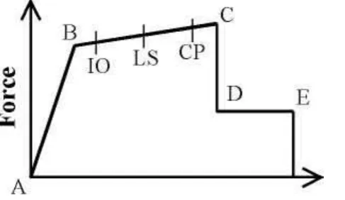
Figure 4.1: Force Deformation for Pushover Hinge
2.1 Plastic Hinge Properties
Comprehensive and complete information about plastic hinge properties of all of the structural segments are rendered by Federal Emergency Management Agency (FEMA) in their Table that is fulfilled by engineers throughout the world. All the information relevant to this table is at disposal as default hinge properties in ETABS software.
2.2 Column Hinge Properties
In accordance with FEMA 356, occurrence of a plastic hinge in a column is as a result of the interaction amongst axial force (P), moment in the stronger (M2) and weaker (M3) direction of the section. Therefore, interaction of PM2- M3 is exerted to illustrate plastic hinges at the two ends of the columns (beginning and ending positions) that are in fact considered as the junction points with the other structural elements (Table 5-6 of FEMA 356).
2.3 Brace Hinge Properties
Nonlinear behavior of brace elements can be best modeled by assuming a hinge (being made under pure axial load) in the middle of the element. An axial load plastic hinge is modeled in the 0.5 relative distances of all bracing elements as per Table 5-6 of FEMA 356 [Appendix] in this study.
2.4 Beam Hinge Properties
Considering the fact that the beam to column connections is rigid, two plastic hinges (one at the beginning and the other one at the end) will be obtained. But for the beams that are braced with eccentric braces, the plastic hinges will occur at the place of fuses. For these kinds of beams the M3 and V2 are taken into consideration.
2.5 Failure Criteria
III. STRUCTURAL MODELLING
For the purpose of this study, nine models of high rise steel frame building (G+10) with different types of eccentric bracings were selected in order to determine the behaviour of steel structure during earthquake in zone IV. The columns are assumed to be fixed at ground level taken as restraints. The building height was chosen to be 35m with storey height of 3.5m respectively. The length of building in X-direction is taken as 32m and in Y- direction is taken as 16m with an opening after 8m in X-direction as well as in Y-direction.
3.1 Structural Configuration
Following are the different types of models selected. One bare frame model
Eccentric backward bracing model Eccentric forward bracing model
Eccentric inverted V or Chevron bracing model Eccentric V bracing model
All these models were analysed for seismic forces using Etabs 13.1.2
3.2 Plan
Fig 3.1: Plan of High Rise Steel Frame
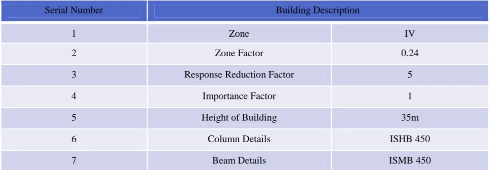
3.3 Building Description
Table 3.1: Building Description
Serial Number Building Description
1 Zone IV
2 Zone Factor 0.24
3 Response Reduction Factor 5
4 Importance Factor 1
5 Height of Building 35m
6 Column Details ISHB 450
8 Bracing Details-1 ISMB 300
9 Bracing Details 2 ISA 200 x 200 x 15
10 Thickness of Slab 125mm
11 Floor to Floor Height 3.5m
12 Grade of Steel Section Fe 250
13 Grade of Concrete M20
14 Floor Finish 1.0 KN/m2
15 Live Load 3.0 KN/m2
3.4 Different Types of Bracings Patterns Used In the Study
Fig 3.2: Eccentric Backward Bracing
Fig 3.3: Eccentric Forward Bracing
IV.RESULTS
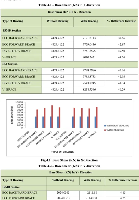
4.1 Base Shear
Table 4.1 – Base Shear (KN) in X-Direction
Base Shear (KN) In X - Direction
Type of Bracing Without Bracing With Bracing % Difference Increase
ISMB Section
ECC BACKWARD BRACE 4424.4122 7121.2113 37.86
ECC FORWARD BRACE 4424.4122 7759.0436 42.97
INVERTED V BRACE 4424.4122 8761.3595 49.50
V- BRACE 4424.4122 8010.2421 44.76
ISA Section
ECC BACKWARD BRACE 4424.4122 7798.5986 43.26
ECC FORWARD BRACE 4424.4122 7753.5733 42.93
INVERTED V BRACE 4424.4122 7543.7245 41.34
V- BRACE 4424.4122 8238.7346 46.29
Fig 4.1: Base Shear (KN) in X-Direction
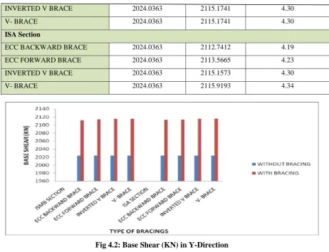
Table 4.2 – Base Shear (KN) in Y-Direction
Base Shear (KN) In Y - Direction
Type of Bracing Without Bracing With Bracing % Difference Increase
ISMB Section
ECC BACKWARD BRACE 2024.0363 2024.0363
2111.86 4.15
INVERTED V BRACE 2024.0363 2115.1741 4.30
V- BRACE 2024.0363 2115.1741 4.30
ISA Section
ECC BACKWARD BRACE 2024.0363 2112.7412 4.19
ECC FORWARD BRACE 2024.0363 2113.5665 4.23
INVERTED V BRACE 2024.0363 2115.1573 4.30
V- BRACE 2024.0363 2115.9193 4.34
Fig 4.2: Base Shear (KN) in Y-Direction
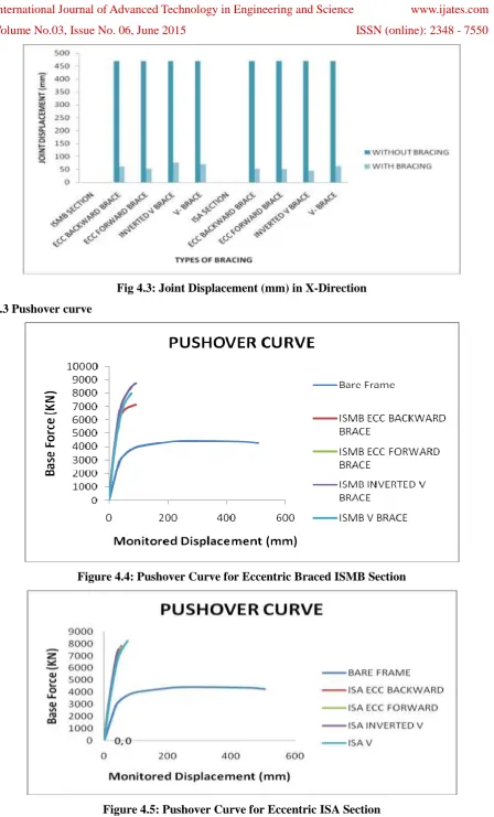
4.2 Joint Displacement
Table 4.3 – Joint Displacement (mm) in X-Direction
JOINT DISPLACEMENT (mm) IN X - DIRECTION
Type Of Bracing
Without Bracing With Bracing % Difference Decreases
ISMB Section
ECC BACKWARD BRACE
469
61.6
86.86
ECC FORWARD BRACE
469
52.3
88.84
INVERTED V BRACE
469
75.5
83.90
V- BRACE
469
70
85.07
ISA Section
ECC BACKWARD BRACE
469
52.5
88.80
ECC FORWARD BRACE
469
51.4
89.04
INVERTED V BRACE
469
45.3
90.34
Fig 4.3: Joint Displacement (mm) in X-Direction
4.3 Pushover curve
Figure 4.4: Pushover Curve for Eccentric Braced ISMB Section
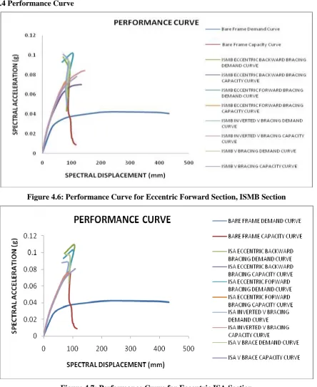
4.4 Performance Curve
Figure 4.6: Performance Curve for Eccentric Forward Section, ISMB Section
Figure 4.7: Performance Curve for Eccentric ISA Section
V. CONCLUSIONS
2. The displacement of the steel bare frame model can be under control by Special Moment Resisting Frame such as steel bracing as a lateral load resisting system. From table 4.3, we can observe that the bare frame with Eccentric Backward Brace, Eccentric Forward Brace, Eccentric V-Brace reduced upto 80-88% as compared with steel bare frame model, whereas in Inverted V-Brace maximum displacement was reduced upto 90% as compared with steel bare frame model. However ISA section reduces more displacement as compared to ISMB section for similar type of bracing.
3. From above tables and grapsh 4.4 & 4.5 and graphs, we can observe that bare frame model has more displacement and less base force when compared to models with bracings. We can also observe that the use of bracings has increased the performance level of steel structure in base shear as well as monitored displacement i.e. roof displacement. The base force has considerably increased and the displacement has decreased. The Eccentric Backward Brace, Eccentric Forward Brace, Eccentric Inverted V Brace and Eccentric V Brace have got more performance base shear and less performance displacement compared to bare frame. ISMB Eccentric Inverted V Brace model has got more stiffness compared to other bracing models. ISMB section gives more stiffness as compared to angle section for similar type of bracings. 4. From the above table and graphs 4.6 & 4.7, it is observed that demand curve and capacity curve are drawn
for high rise steel frame with and without bracings for seismic zone IV. The Eccentric Inverted V Brace model has increased the performance level as compared to other bracing models. It can also be seen that models with bracings have lesser vulnerability as compared to the frames without bracings. ISMB section gives more Performance point as compared to angle section for similar types of bracings.
5. Pushover analysis is an appreciable approach to determine the adequacy of a structure under earthquake loading
REFERENCES
[1]. Dr. S. N. Tande, Amol A. Sankpal, 2014, presented paper on “Study of Inelastic Behavior of Eccentrically Braced Frames under Non Linear Range”.
[2]. Krishnaraj R. Chavan, H.S.Jadhav, 2014, presented paper on “Seismic Response of RC Building with Different Arrangement of Steel Bracing System”
[3]. Mazen Ali Musmar, 2013, presented paper on “Effect of link dimensions on d type eccentric steel frames”. [4]. A. Mortezaeiand H. R. Ronagh, 2013 presented paper on “Effectiveness of modified pushover analysis
procedure for the estimation of seismic demands of buildings subjected to near-fault ground motions having fling step”
[5]. J. J. G Ramsay, A. Fussell, and R. G. Wilkinson, 2013 presented a paper on “Design of replaceable-link eccentric braced frames in post-earthquake Christchurch”