“Effect of Divergence Angle on the
Performance and Flow Analysis of 3D
Annular Diffuser of an Aircraft Engine using
CFD Technique”
Sharan Padashetty1, Pravin Honguntikar2, K. Rajagopal3 1
Ph.D Research Scholar, JNTU, Hyderabad, TS, India & Associate Professor, PDA College of Engineering, Kalaburagi, Karnataka, India.
2
Professor, Dept of Mechanical Engineering, PDA College of Engineering, Kalaburagi, Karnataka, India.
3
Vice Chancellor, Sri Krishnadevaraya University, Anantapur, AP, India.
ABSTRACT: The performance characteristics of diffusers depends on their geometry and the inlet conditions. The present investigation attempts to select an optimal divergence angle of diffuser. This is analysed on the basis of static pressure recovery and total pressure loss coefficients. Simulation of air flow in various annular diffuser geometry is carried out using ANSYS FLUENT. The geometric limitations of the aircraft engines in which the diffusers are to be designed so as to get maximum pressure recovery within shortest possible length led to the design and development of annular diffuser.
Keywords: Annular diffuser, Gas turbine aircraft engine, divergence angle, static pressure recovery coefficient, velocity vector contours.
1. INTRODUCTION
Annular diffuser as an integral component of gas turbine engines of high-speed aircraft. The performance of diffuser is dependent on geometrical and dynamical parameter. The design and optimization of diffuser geometry to achieve
the best performance of the combustor is quite complex. Annular diffuser naturally exist in the gas turbines of aircraft because of presence of central hub or shaft. The annular diffuser have superior performance compared to conical or simular diffuser because of the presence of hub which act as a guide to the flow Kline SJ [1].
Majority of the previous research focussed primarily on 2D annular diffuser. Previous work by Cherry et al 2008 [2] stressed the need for rigorous database of experiments on separated flow to compare with CFD calculation and simulation. The geometry features of diffuser made to replicate general electric 8362 turbine CD diffuser as an author by Sovran and Klump (1987) [3] and Jason J Dunn 2007 [4]. Design and optimization of diffuser geometry to achieve best performance of combustor involves the compressor producing high-pressure ratio with minimum number of stages resulting in high axial velocity at compressor exit S.N. Singh, V. Seshadri, K. Saha, K.K. Vempati and S. Bharani 2005 [5].
2. GEOMETRY AND MATHEMATICAL FORMULATION OF ANNULAR DIFFUSER:
2.1 Geometry:
Geometry of the diffuser is created in ANSYS Designer modular. 3D model is generated using ANSYS 16.
FIG.1 Key dimension for Annular diffuser geometry
Table-1 Geometrical Features of Diffusers investigated
Diffuser 1 Diffuser 2 Diffuser 3 Diffuser 4 Diffusers angle 0 9º 15º 22º 29º
Radius of Hub RH1 2.108 cm 2.108 cm 2.108 cm 2.108 cm
Radius of diffuser at inlet RT1 3.896 cm 3.896 cm 3.896 cm 3.896 cm
Difference between radius of inlet and hub radius
R1 1.788 cm 1.788 cm 1.788 cm 1.788 cm
Cross-section area at inlet A1 31.627cm2 31.627cm2 31.627cm2 31.627cm2 Cross-section area at outlet A2 86.63cm2 138.153cm2 217.20cm2 316.58cm2 Area Ratio AR 2.73 4.36 6.86 10.01 Diffuser wall length L0 11.542cm 11.854cm 12.410cm 13.250cm
Diffuser axial length L 11.40cm 11.40cm 11.40cm 11.40cm
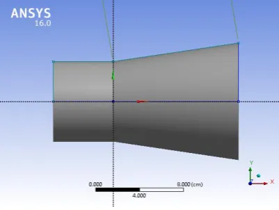
2.2 Geometry in CFD analysis modular design:
Geometry in ANSYS design module is created for preparation and analysing 2D and 3D models are generated.
Figure 2 Geometry of Diffuser with Figure 3 Geometry of Diffuser with 90 diverganceangle 150 diverganceangle
Figure 4 Geometry of Diffuser Figure 5 Geometry of Diffuser with with 220 diverganceangle 290 diverganceangle
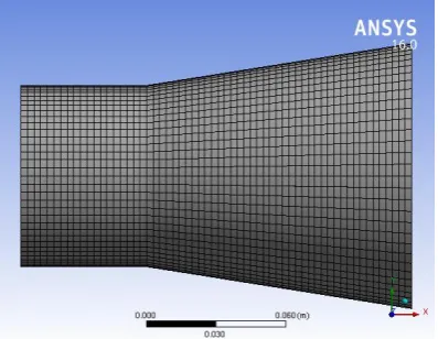
2.3 ANSYS Workbench Mesh:
This work gives an insight of the findings that are obtained from the analysis of the 3-D annular diffuser done in CFD. Different modifications on the basic geometry were investigated to optimize the performance of the diffuser. First a model for the base diffuser was developed by taking its geometric data from literature and the performance data serve as a reference for comparing the
(a) 9º divergence angle of diffuser (b) 15º divergence angle of diffuser
Figure 6 Meshed model of the annular diffuser
The number of nodes used to obtain acceptable, mesh-independent solutions is 43000. Validation of the numerical solutions was obtained by comparing the values of Pressure coefficient with experimental results.
2.4 Boundary Condition & Fluent Setting (Preprocessing):
All turbulence models implemented a COUPLED scheme to couple the pressure and velocity. Furthermore, the spatial discretization was accomplished by a second-order accurate upwind scheme for the momentum and a FLUENT
standard scheme for the pressure. Any additional closure equations for the various turbulence models were spatially discretized by second-order accurate upwind schemes. In all cases, the corresponding calculation residuals were monitored to convergence at 1×10-05. These residuals included continuity, x-velocity, and y-velocity for all turbulence models. Beyond these generic residuals, any additional closure equations gave additional terms to monitor. The fluid properties were carefully chosen to ensure a matched Reynolds number with the experimental data.
Figure 7 Residual plot for analysis
The present approach requires the consideration of three sets of interlocking equations: (a) momentum and mass conservation for turbulent flow, (b) turbulence model (Shear Stress Transport), and (c) transitional flow model.
The first of the sets encompasses the equation of continuity and the RANS equations, which are
𝜕𝑢𝑖
𝜕𝑥𝑖 = 0
𝜌(𝜇𝑖 𝜕𝑢𝑗 𝜕𝑥𝑖) = − 𝜕𝑝 𝜕𝑥𝑗 + 𝜕 𝜕𝑥𝑖((𝜇 + 𝜇𝑡) 𝜕𝑢𝑗 𝜕𝑥𝑖)
Here, 𝜇𝑡is the so-called turbulent viscosity. To obtain values of this quantity, it is necessary to make use of a
supplementary pair of equations
Boundary conditions for the numerical simulation include the no-slip and permeability conditions on all solid boundaries. At the inlet of the diffuser, a fully developed velocity profile, either laminar or turbulent, depending on the situation under consideration, was imposed. At the downstream end of the solution domain, the streamwise second derivatives of the velocities were required to be zero Boundary Condition
Table-2: Boundary conditions
Solver Type Pressure Based
Problem model k-𝜀 Turbulence Model With Wall enhanced treatment Fluid Air
Casing Acrylic Mass Flow rate 0.002259kg/sec Hydraulic Diameter 1.788 cm
3. RESULTS AND DISCUSSION
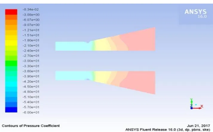
3.1 Contours of Pressure coefficient
The pressure coefficient distribution along the diffuser is shown in the following figures at different diveregence angles(90 ,150,220&290)
Figure 8 Contours of pressure coefficient for 90 divergence angle of diffuser
The pressure coefficient is dimensionless number which describes the relative pressures through out a flow field in fluid dynamics. Every point in the fluid flow has its own unique pressure coefficient. The distribution of the pressure coeffiecient along the diffuser is simulated on xy plane section
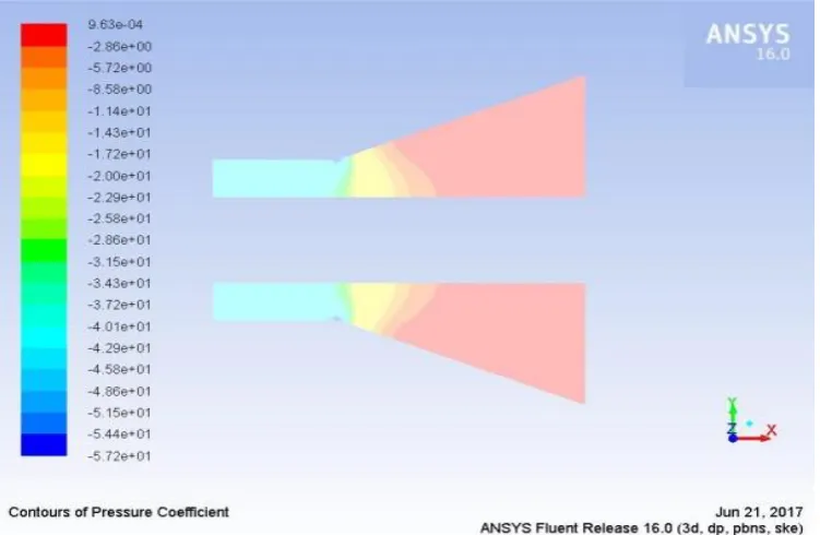
Figure 10 Contours of pressure coefficient for 22º divergence angle of diffuser
Figure 11 Contours of pressure coefficient for 29º divergence angle of diffuser
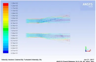
3.2 Contours of velocity Vectors
Figure 12 Velocity vectors of 9º divergence angle of diffuser
Figure 13 Velocity Vectors for 150 divergence angle of diffuser
Figure 14 Flow separation and velocity vectors for 220divergence angle
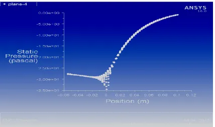
6.3 Divergence angle vs Pressure Recovery
Graphs are plotted taking horizontal distance on X axis and pressure coefficient on Y- axis to know the impact of the divergence angle on the pressure coefficient. The graphs are shown below
Figure 16 Plot for Static pressure recovery coefficient for 15º divergence angle of diffuser
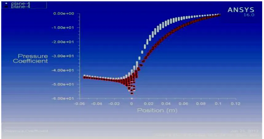
Figure 18 Plot for Static pressure recovery coefficient for 9º, 15º and 22º divergence angle of diffusers
From the above figure we can observe that pressure coefficient increseas as the angle of divergence increases. Due to this increase in pressure coeffiecient the pressure recovery increases which is very essential for a diffuser. Increase in pressure cofficient is very less in 220 and 290 as compared to intial investigated diffuser of divergence angle of 9º and 15º
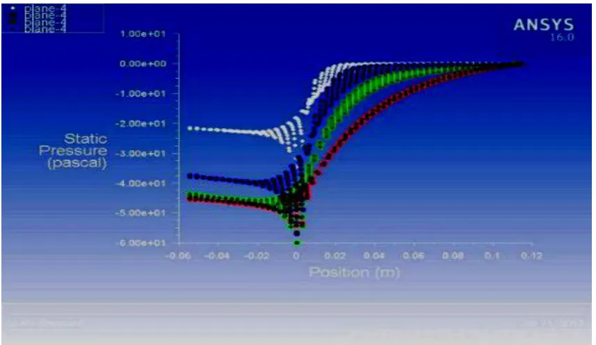
Figure 19 Plot for Static pressure recovery coefficient for 9º, 15º, 22º and 29º divergence angle of diffuser
CONCLUSIONS
Following inferences have been drawn from the predicted CFD results for various divergence angle of diffuser. The discussions have clearly highlighted the following aspects of diffuser flow analysis.
1. Pressure recovery within the diffuser increases as flow proceeds except at the beginning stage of the diffusers while velocity decreases as the flow proceeds.
coefficient on y-axis to study the effect of divergence angle on the pressure coefficient. 3. It is observed that pressure coefficient increases
as the angle of divergence increases. Due to this increase in pressure coefficient the pressure recovery increases.
4. Effect of divergence angle of diffuser is indicated on the pressure coefficient plot. Flow separation begins as the divergence angle increases above 20º which results in pressure loss. Increase in pressure coefficient is noticed drastically for diffuser with divergence angle from 15º to 20º.
5. Increase in divergence angle more than 22º has no effect on pressure recovery ans pressure coefficient.
REFERENCES
1. Kline S.J. on the nature of stall. Trans. ASME Ser. D, 1959,
81, 305-320.
2. Cherry EM, Elkins CJ, Eaton JK, 2008. “Geometric
Sensitivity of 3D separated flows”, International Journal of Heat and Fluid Flow, 29, 803-811.
3. Sovran G and Klomp ED, Fluid Mechanics of Internal Flow,
edited by Sovran G. (Elsevier Science Publisher, Amstradam), 1967, 270.
4. Jason J. Dunn, 2007, “On the nature of flow in separated annular diffuser”, BSAE University of Central Florida, Orlando.
5. SN Singh, V Sheshadri, K Saha, KK Vempati and S
Bharani, “Effect of inlet swirl on the performance of annular diffuser having same equivalent cone angle”, Vol.220, 2005, Journal of Aerospace Engineering, 129-143.
6. A Sheeba, V Ganesan, “Modelling of annular pre-diffuser
for marine gas turbine combustor with CFD”, Journal of Naval Architecture and Marine Engineering, 2005, 41-52.
APPENDIX:
Notation:
AR Area Ratio
L0 Diffuser wall length
L Diffuser Axial Length
Diffuser Divergence Angle RH Radius of Hub